







If you’d rather listen than read, feel free to play the audio file below for the rest of this article.
Electrical protection in different conditions
Electrical protection refers to the measures that must be taken in electrical installations so that the hazards caused by electric current do not lead to injury to people, animals, devices, generators, loads, and current-carrying wires.
Protection of wires and cables
All wires and cables must be protected against overload and short circuit. To protect a wire against overload, thermal switches (bimetal) or fuses can be used.
If the details you gathered about wires and cables were interesting and insightful, you may find diving deeper into Wire Is Suitable for Industry equally captivating.
Protection of loads and electrical devices
Loads and electrical devices must be protected against potential faults such as short circuit and overload. To protect these devices, fuses and magnetic or thermal circuit breakers are usually installed upstream of the load/device and selected according to the rated current of that device.
Protection of people
One of the most important points in electrical protection is the issue of electric shock to humans.
Any possible overcurrent that occurs in live parts must not cause damage or injury to people, devices, or equipment. Therefore, protection against overcurrent is necessary and is done by one of the following methods:
- Automatic disconnection of supply when an overcurrent occurs before the overcurrent reaches a dangerous level (considering the duration of the overcurrent).
- Limiting the maximum overcurrent to a safe level (considering the duration of the overcurrent).
Types of faults caused by electric current
Electrical faults can mainly be divided into three categories:
- Body fault: connection of one of the live conductors to the metal body of a device.
- Short circuit: connection of two bare conductors that have an electrical potential difference to each other.
- Earth fault: connection of one current-carrying conductor to earth (ground).
The faults described above can usually occur in two forms: complete and incomplete. If the fault is complete, it means there is no resistance at the fault location and a high current passes through that point. But if the fault is incomplete, there is some resistance at the fault location, so the fault current is lower than in the previous case. This type of fault is often dangerous because it is not easily detectable. In each of the above fault cases, a specific protective system must be used.
Most electric shocks occur when the insulation of electrical wires is torn, defective, or has a crack. Also, the insulation of internal motor windings or electrical devices may wear or burn and, by contacting the device body, create hazards. This case is more common in electric motors or devices that are movable.
If the current passing through the body exceeds 30 mA, it will be dangerous. The body resistance against the passage of electric current varies and ranges from 500 to 5000 ohms and more.
This difference in resistance depends on the person’s characteristics and the environmental conditions. For example, if the person’s skin is dry, the body resistance is higher than when the skin is moist. Under unfavorable conditions and when protective measures are not fully taken, a potential difference of 15 to 20 V may be dangerous for a person; of course, the duration and type of current also affect the severity of electric shock.
The 500 Ω figure is internal body resistance, measured hand-to-hand with the skin bypassed. Total body impedance including dry skin is far higher at low voltages — IEC 60479-1 gives roughly 3,000–6,000 Ω at 25 V, falling as voltage rises because skin breaks down above about 200 V.
This is why SELV systems at 24 V AC are treated as safe: the conventional touch-voltage limit is 50 V AC, and 24 V sits well below it. Extra-low voltage is a protective measure, not a residual hazard.
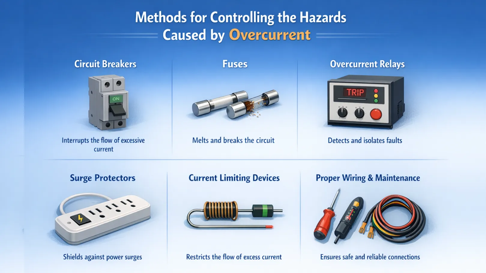
Methods for controlling the hazards caused by overcurrent
When the current exceeds the rated value of wiring and equipment, a hazard is created. In this condition, the circuit wiring and equipment cannot carry the current without heating up or even melting. Not only will wiring and equipment be damaged, but the high conductor temperature can also cause fire. To prevent this, an overcurrent protective device (a circuit breaker or a fuse) must be used in the circuit.
This device automatically disconnects the circuit when it detects current exceeding the rated current of the wiring and equipment. Overcurrent may occur due to excessive load, a short-circuit circuit, or a ground fault.
Overcurrent protective devices are designed to protect equipment and buildings against fire. These devices cannot protect a person against electric shock. If the current in the circuit is very high, the device will disconnect the current. A circuit breaker or fuse will not stop relatively small currents that can cause injury or death.
A 20 A household breaker will not operate until circuit current exceeds 20 A. But currents far below that are lethal through the body: IEC 60479-1 places the let-go threshold around 10 mA, with ventricular fibrillation risk rising above roughly 30–40 mA at 50/60 Hz. A fault passing 100 mA through a person is nowhere near enough to trip the breaker protecting the circuit.
This is precisely why RCDs exist. A 30 mA RCD detects the imbalance between line and neutral current, which an overcurrent device cannot see at all.
Overcurrent protective devices are not permitted to be installed in areas exposed to physical damage or high-risk environments. These devices may become hot and occasionally spark, which can cause fire or explosion in certain areas.
If an overcurrent protective device disconnects the circuit, it may be due to a problem somewhere along the circuit. (For circuit breakers, repeated tripping may indicate that the breaker itself is defective.) When the circuit breaker trips or the fuse melts, the cause must be investigated.
A circuit breaker is an overcurrent protective device and an automatic switch installed in the circuit. The breaker trips when an excessively high current passes through it. The breaker should not be used routinely to turn the power supply on or off unless it is designed for this purpose and marked SWD.
Fuses are the simplest and oldest protective devices. Fuses are special wires with a small cross-sectional area installed in series in the electrical circuit. The fuse wire size is selected so that the rated current can pass without excessive heating and melting; and if the current exceeds the allowable limit due to overload or short circuit, the fuse wire heats up and eventually melts, disconnecting the circuit.
A small and short-duration overload usually does not damage the circuit and equipment, and there is no need for the fuse to disconnect the circuit. However, in short-circuit cases, the fuse must act quickly and disconnect the circuit.
If the content related to overcurrent was both interesting and helpful, further study of overvoltage category concepts could be just as fascinating.
Protection against short circuit
A short circuit occurs when two uninsulated conductors come into contact with each other. In this condition, the resistance becomes close to zero. This current is several times the normal operating current. The current generated during a short circuit must be disconnected immediately. In general, short-circuit current in a faulty circuit occurs due to the connection of one or more conductors of the circuit (which normally have different potentials) to other conductors through very low impedance. Also, short-circuit current typically passes through earth. Therefore, special attention must be paid to the correct design of the protective conductor PE (earth). Bonding conductors, earthing conductors, and other components intended to carry fault current must conduct the current without creating excessive temperature.
Why Overcurrent Protection Doesn’t Prevent Equipment Damage
An overcurrent device has one job: open the circuit before the conductor overheats. It protects the wiring and the building. It does not protect the equipment on the end of that circuit, and it is not designed to.
The reason is timing. A standard circuit breaker clearing a 40 kA fault takes around three cycles — 50 ms at 50 Hz. In that time the fault current has already reached its peak and passed substantial energy through every component in the loop. The breaker prevented a fire; the motor, the contactor and the cable insulation may already be destroyed.
Two parameters describe what actually gets through:
- Peak let-through current (I_p) — the highest instantaneous current the device allows before interrupting. This causes the electromagnetic forces that deform busbars and tear terminations apart.
- Let-through energy (I²t) — the thermal energy passed during clearing, in A²s. This is what melts contacts and cooks insulation.
Current-limiting devices — current-limiting fuses and current-limiting breakers — interrupt within the first quarter-cycle, before the fault current can rise to its prospective peak. That can reduce peak let-through by an order of magnitude and let-through energy by considerably more.
The practical consequence for specification: when downstream equipment has a short-circuit withstand rating lower than the available fault current, a standard overcurrent device is not sufficient. You need a current-limiting device upstream, and the let-through curves have to be checked against the equipment’s withstand rating — not just the breaker’s interrupting rating.
Using a magnetic relay for overcurrent protection during short circuit
To disconnect current quickly when a short circuit occurs, magnetic relays and devices that include magnetic relays in their structure are used. Magnetic relays consist of an iron core with a coil wound around it; these coils are placed in series with the phase conductor.
The passage of short-circuit current through the coils creates a strong magnetic field, leading to movement of the iron core and ultimately movement of the trip lever. The trip contact also acts in the circuit like a STOP pushbutton. Magnetic relays exist together with thermal relays in MCBs, molded case circuit breakers, etc.
Difference between overload and overcurrent
When the number of devices operating in a circuit increases, or a device draws current higher than its design value, this is called an overload. For example, a motor that normally consumes 10 A may draw 20 to 30 A under overload conditions. This current causes the motor to heat up, and if the overload relay does not disconnect the circuit, the motor will be damaged in the short term.
Overload current in a healthy circuit may occur due to reasons such as miscalculation and incorrect selection of circuit equipment in design and installation, load growth over time, or a fault in the device (for example, increased friction in bearings), etc. But overcurrent results from device fault or a conductor-to-body fault, short circuit, or earth fault.
Temporary overload during starting current
The starting current of electric motors is higher than the motor’s rated current. The protective switch selected to protect the motor must be able to pass a current higher than the rated value for a short time. Otherwise, each time the motor starts, the circuit will trip and the motor will be disconnected.
Overload relays are used for motor loads that require starting current and have the following characteristics:
- Temporary overloads due to starting can pass without tripping the circuit.
- If the current exceeds the rated current for a specified time, they trip and open the circuit.
- After the overload is cleared, they reset.
Electrical equipment for overcurrent protection
Miniature circuit breaker (MCB) suitable for short-circuit and overload protection
A miniature circuit breaker (MCB) is essentially an automatic switch that has both load-breaking and isolating functions, and its role is to disconnect the circuit in the event of short circuit or overload. An MCB consists of three parts: a magnetic relay for short-circuit protection, a thermal relay or bimetal relay for overload protection, and an isolator. This breaker has two parts: magnetic (high current in a short time) and thermal (gradual current increase).
MCBs of Class C are suitable for protecting motor loads. These breakers trip at currents higher than 5 to 10 times the rated current. In other words, they tolerate motor starting current.
Thermal switch or bimetal for overload protection
Another component that protects equipment such as motors against overload is the bimetal relay. The structure of a bimetal switch consists of two metals with different coefficients of linear expansion. When current passes and the temperature rises, one expands more than the other, causing the strip to bend; this movement is transferred to the trip lever and disconnects the circuit.
Motor protection circuit breaker and short-circuit/overload protection
This breaker is one of the components that protects the motor against short circuit and overload. If the current increases beyond the set value, the thermal relay operates and disconnects the circuit, and this action occurs quickly in a short time.
Detecting leakage current using an earth fault relay
An earth fault relay is used to detect and command circuit disconnection in the event of an earth fault or leakage current. Using a core-balance ring CT, it detects residual current above the permissible limit; in this condition, the relay output is activated. A shunt trip relay or undervoltage relay, a contactor, or an automatic circuit breaker is placed in the relay path so that when a fault occurs, it disconnects the supply circuit.
The earth fault relay together with the CT core-balance current transformer are used as complementary parts to detect leakage current. When leakage current is detected, the earth fault relay operates and commands the contactor or automatic circuit breaker to trip.
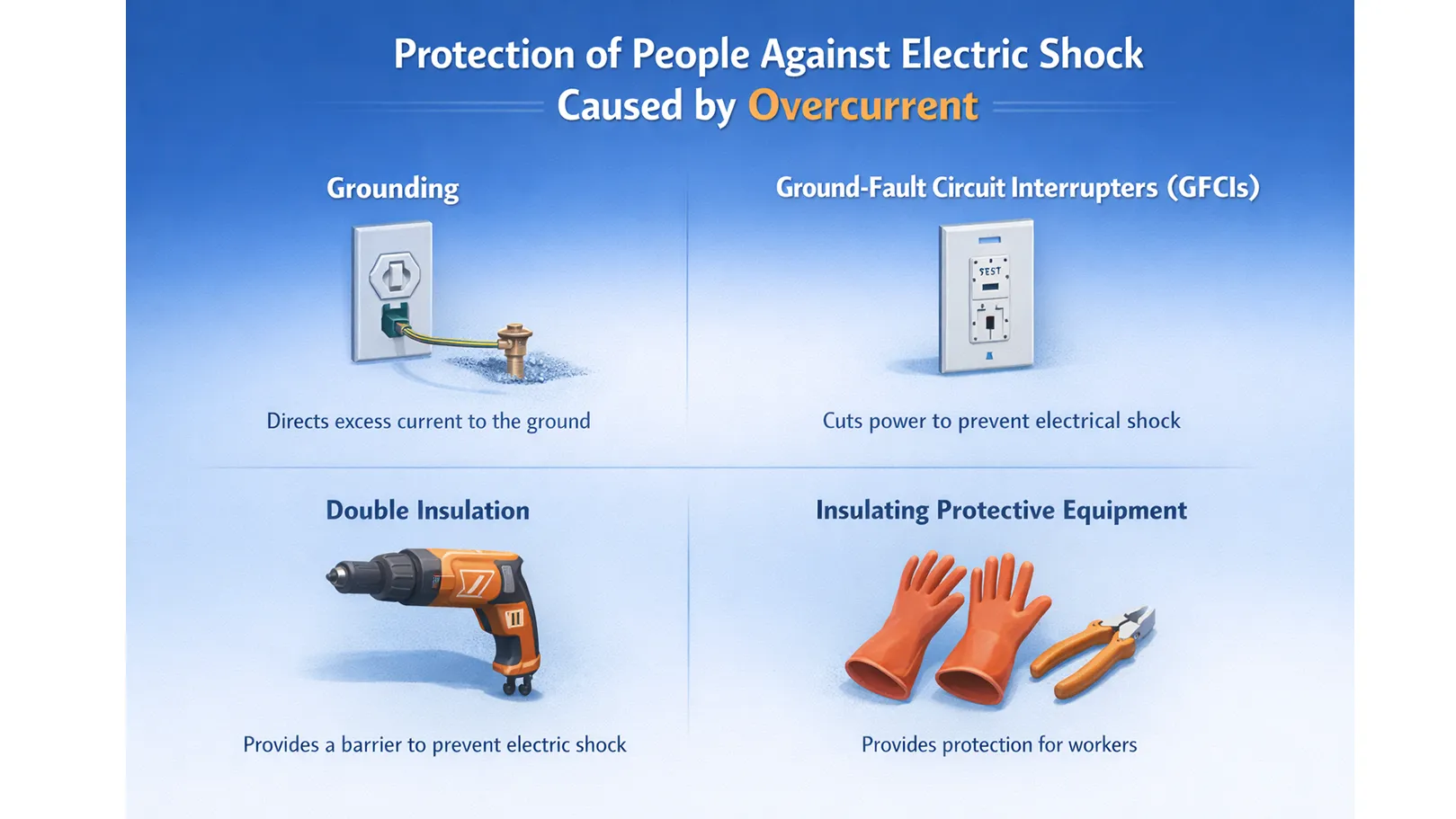
Protection of people against electric shock caused by overcurrent
Protection against electric shock can be provided for people by the following methods:
Bonding for equipotentialization
In each building, main bonding is performed by electrically connecting the earth and neutral and PEN conductors, main water and gas pipes, main metal riser pipes, metal pipes of services, main metal parts of the foundation, and the main and auxiliary earthing electrodes to each other. Also, supplementary bonding for equipotentialization is carried out by electrically connecting all accessible metal parts on site, metal bodies of electrical and non-electrical devices, and extraneous conductive parts to the earth conductor.
(Protection by connecting devices together with a conductor wire)
If two or more electrical devices close to each other, due to various reasons such as a body fault, have different potentials and a worker’s hand simultaneously touches both, then even with insulating shoes, a dangerous current will pass through the worker’s body.
In fact, by bonding, the devices are connected to each other via a conductor so that in the above cases there is no potential difference between them.
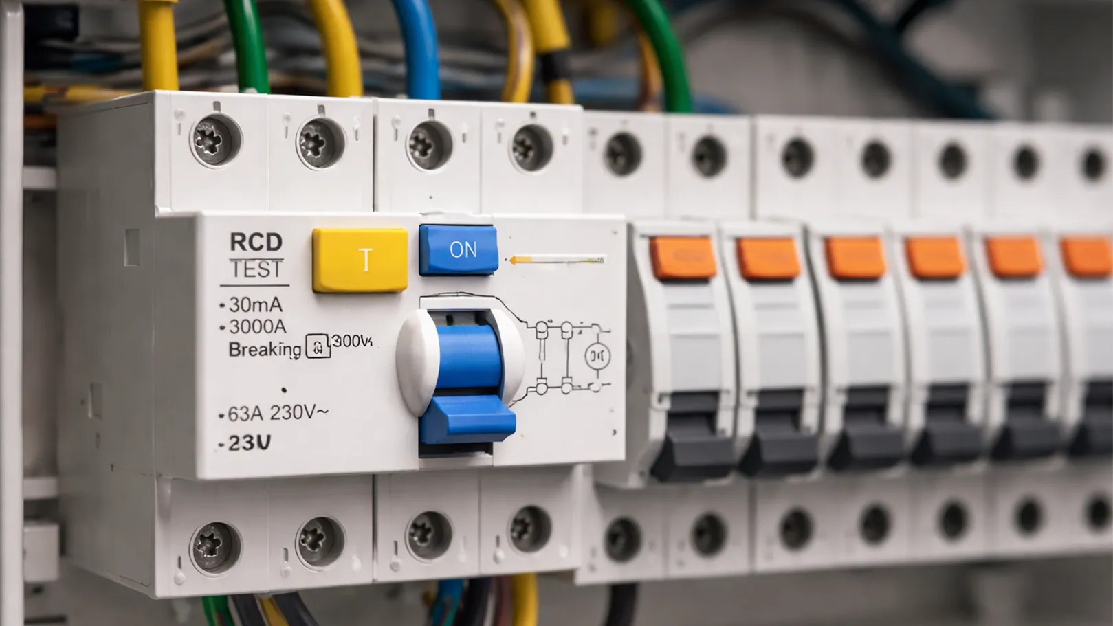
Protection using an RCD (residual current device)
An RCD is installed at the incoming side of panels for protection against electric shock. If there is a difference between the phase and neutral currents of a device, it operates; and if a body fault occurs and results in leakage current to earth, the neutral current becomes lower than the phase current. The phase and neutral currents pass through two coils wound in opposite directions. Under normal conditions without a body fault, the current in both coils is equal and no magnetic field is produced. But due to the difference between the two currents entering these coils, a magnetic field is produced, and the magnetic core causes the circuit to trip.
Protection against current through the earthing (grounding) system
Grounding is the connection of an electrical system to earth using a conductor. Excess and stray (leakage) current is transferred through this conductor to a component buried in the ground (the earth electrode). Grounding prevents unwanted current from entering electrical equipment.
Sometimes an electrical system receives a voltage higher than what it was designed to carry. These high voltages may result from lightning strikes, sudden current increases, or contact with high-voltage lines. Sometimes a fault occurs in a device that allows exposed metal parts to become energized. Grounding helps protect people working on the system, the system itself, and others who use tools and equipment.
Grounding provides a path for unwanted currents produced by high voltages to flow.
Earth electrode
An earth electrode is a conductive body placed in the ground to which the earthing conductor is connected. Electrodes are made in various forms: vertical, plate, and horizontal.
Overcurrent Protection Using a 1:1 Isolation Transformer
In this type of protection, a transformer with a turns ratio of 1 is used. For example, in a 220 V network, the primary and secondary voltages are both 220 V. In this protection method, if the phase conductor of the transformer secondary comes into contact with the metal body of the device and the person also touches the device body and the ground, no danger will threaten the person.
Because the transformer phase conductor is only at voltage relative to the transformer secondary neutral conductor. These transformers are produced in three-phase and single-phase types with currents of 10, 16, and 25 A.
Protection using low voltage
Voltages of 50 V AC or below (SELV/PELV per IEC 60364-4-41) are used for protection, and for this purpose a transformer with two separate windings must be used. This type of protection can be used in metal cabins, toys, etc. Also, for places where livestock are kept and there is a possibility of wire damage or wire chewing by livestock, this method can be used.
Protection by insulation
In insulation-based protection, all accessible parts of the load that may have voltage to earth in the event of a body fault are insulated. Also, by insulating around devices such as the floor or walls, the touch voltage relative to earth can be protected. Of course, such protection can only be implemented for devices that are fixed in one place.
In any case, for full protection, people must be sufficiently trained and the system must always be tested. Continuous and regular checking of electrical devices, as part of safety methods, must be performed by trained personnel. Checking means answering questions such as:
- Is the permissible voltage on the device nameplate the same as our system voltage, and if not, what is the difference?
- Is the plug healthy and of good quality?
- When the wire exits the device, is it protected against the metal body by a durable rubber grommet or not?
- Is the wire generally healthy? Is there tearing or damage?
- Is the device’s own switch, and the switch upstream of the socket, in the OFF position or not?
- Is the wire generally routed above the worker’s head height at the work location or not?
For medium-voltage switchgear, internal arc classification and type testing are covered in IEC 62271-200.
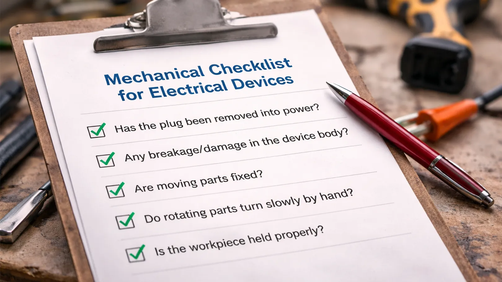
Mechanical checklist for electrical devices
- Before any work such as blade adjustment, tightening a chuck, etc., has the plug been removed from power or not?
- Is there any breakage or damage in the device body or not?
- Are moving parts such as the drill fixed or not?
- Do rotating parts turn slowly by hand or not?
- Is the workpiece held properly or not?
Conclusion
Overcurrent protection is essential to prevent overheating, equipment damage, and fire, and it must be selected based on the type of fault and the required disconnection time. Short circuits require fast-acting magnetic protection, while overload conditions typically rely on thermal protection and overload relays. For human safety, measures such as bonding, RCDs, proper grounding, and appropriate insulation must be applied and regularly checked to ensure the system remains safe and reliable.



Rate this article
Choose a rating from 1 to 5 stars.
No ratings yet