

Prefer listening? You can play the audio version of the rest of this article below.
Earthing Systems and Grounding: Why This Project Started
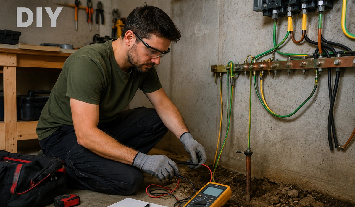
My workshop started as a simple space with a small consumer unit and a few socket outlets.
Then, like most DIY spaces, it slowly turned into a mixed electrical environment. First came the compressor. Then a TIG welder. Then a small VFD for a converted lathe. Then measurement gear that hated electrical noise. Suddenly, I had a setup where power quality, fault protection, and grounding layout all mattered.
The warning signs were subtle at first:
- occasional tingling sensation on a metal machine frame (very slight, but unacceptable)
- random RCD trips when the welder and VFD ran together
- noisy readings on a panel meter
- one UPS complaining about “wiring fault”
That was the moment I stopped treating earthing as an afterthought.
I started reading more seriously about standardized earthing arrangements and learned that the choice of earthing system affects both fault protection behavior and practical design decisions. Schneider’s Electrical Installation Guide (wiki) describes earthing schemes as standardized combinations of source earthing, exposed conductive part connections, conductor arrangements, and protection methods.
This reference page is useful for readers who want to study the topic beyond this article.
Earthing Systems and Grounding Basics; I Had to Unlearn
Before I touched a single conductor, I had to fix my terminology.
I had been mixing up:
- earthing/grounding system type (TT, TN, IT)
- protective conductor arrangement (TN-S, TN-C, TN-C-S)
- earth resistance (quality of the electrode-to-soil connection)
- bonding (equipotential connections between metal parts)
Those are related, but not the same thing.
A big breakthrough for me was understanding the IEC naming logic. Under IEC terminology, low-voltage earthing arrangements are grouped into three families: TN, TT, and IT. The first letter describes the source relationship to earth, the second letter describes the exposed conductive parts’ relationship to earth, and extra letters like S and C show whether neutral and protective functions are separate or combined.
You can find more background information and related technical notes through this reference link.
That one point immediately cleared up the “4 types or 5 types?” confusion.
Earthing Systems: Why Some People Say 4 Types and Others Say 5 Types
This confused me for longer than I want to admit.
Here’s the practical answer I now use:
- IEC families (strict classification): 3 types
- TN
- TT
- IT
- Common field-level low-voltage arrangements (practical counting): often 4 or 5
- TN-S
- TN-C
- TN-C-S
- TT
- IT
So, when someone asks, “What are the 4 types of earthing systems?” they are often talking about the common arrangements used in practice (sometimes omitting TN-C in final circuits because it is restricted in many situations). When someone asks for 5, they are usually counting TN-C separately as well.
In other words, both answers can be “right” depending on whether you’re counting families or practical variants.
If you are looking for more information about earthing system types, it is recommended not to miss reading this article.
Earthing Systems Comparison That Changed My Design Decisions
Once I stopped guessing, I made myself a comparison sheet. That sheet ended up being the most useful thing in the project.
Here’s a simplified version of the table I used.
| Earthing system | Source neutral earthed? | Exposed conductive parts connected to | PE/N relationship | Typical protection behavior | My takeaway |
|---|---|---|---|---|---|
| TT | Yes | Local earth electrode | Separate from supply neutral-earth path | RCDs are central to protection | Great when supply earth quality is uncertain, but leakage/noise and RCD coordination need care |
| TN-S | Yes | Source earth/neutral point via PE conductor | Separate PE and N | Low-impedance fault path, overcurrent devices + RCDs as needed | Clean and reliable for mixed loads, especially sensitive electronics |
| TN-C | Yes | PEN conductor (combined PE+N) | Combined (PEN) | Economical, but restrictions and risks | I avoid this in workshop final circuits |
| TN-C-S | Yes | PEN upstream, split to PE and N downstream | Combined then separate | Common utility practice in many regions | Practical, but PEN integrity becomes critical |
| IT | No direct earth, or via impedance | Local earthing of exposed parts | Depends on system design | First fault monitored (IMD), second fault trips | Excellent continuity in critical applications, but not a casual DIY choice |
Schneider’s guide was especially useful for understanding the practical characteristics: TT typically uses RCDs, TN systems rely on low-impedance fault paths and overcurrent protection for first faults, and IT systems use insulation monitoring and can continue operating through a first fault under monitored conditions. (Electrical Installation)
If the information related to grounding earthing was interesting and informative to you, researching electrical standards can be very engaging.
TT Earthing Systems in My Workshop: The First Attempt and the First Mistake
My first approach was basically a “local rod and hope” TT-style mindset. I installed a ground rod, bonded the panel enclosure, machine frames, and cable trays, and felt pretty proud of the result.
Then the nuisance trips started.
The real issue wasn’t that TT is “bad.” It was that I had built a messy TT implementation:
- long protective conductor runs with poor routing
- mixed noisy loads and sensitive loads on the same RCD strategy
- questionable bonding on an older machine frame
- no real testing beyond continuity checks
What I learned is that in TT systems, RCD selection and circuit grouping matter a lot. Schneider’s guide explicitly notes TT protection of persons relies on exposed conductive parts being earthed and RCDs being used. (Electrical Installation)
Earthing Systems Lesson From TT: “It Works” Is Not the Same as “It Is Robust”
My setup technically worked.
But it wasn’t robust.
When the welder and VFD were active, leakage currents and noise made the whole installation feel unpredictable. The RCD wasn’t “wrong”; my design assumptions were. I had treated all loads like they behaved the same way.
That was the moment I split loads into groups and started thinking like a panel builder, not just a hobbyist:
- dirty loads (welder, VFD)
- general loads (lighting, outlets)
- sensitive loads (meters, bench instruments, UPS)
That simple separation improved stability more than my first round of hardware changes.
For a comprehensive understanding of overcurrent protection, we highly recommend reviewing this article.
TN Earthing Systems in My Project Research: Why TN-S Became My Reference Model
The more I tested, the more I appreciated why engineers like TN-S behavior for many industrial/commercial installations.
In a TN system, the exposed conductive parts are tied back to the source earthing point, and protection is based on a low-impedance fault path so overcurrent devices can clear a first fault quickly (with RCDs used where required or desirable). Schneider summarizes this clearly in its TN system characteristics. (Electrical Installation)
For my workshop, I was not redesigning the utility network, but I was redesigning my downstream wiring philosophy. So, I adopted a TN-S-like discipline inside the panel:
- keep PE and N separate
- avoid casual neutral-earth “fixes”
- route PE deliberately
- improve bonding continuity
- segregate noisy and sensitive circuits
That instantly reduced mysterious behavior.
Earthing Systems and TN-S: Why Separate PE and Neutral Helped My Measurements
The biggest improvement wasn’t just safety—it was signal cleanliness.
Schneider’s guide highlights a practical TN-S advantage: the separation of neutral and protection provides a “clean PE,” which is beneficial for computer systems and sensitive equipment.
This source provides further explanation and can help you compare the details more accurately.
That matched exactly what I saw.
My panel meter readings stopped drifting when the VFD ramped up. The UPS stopped complaining. Even a cheap oscilloscope probe reference behaved better on the machine frame.
I’m not saying TN-S magically solves all EMC problems. It doesn’t.
But separating PE and N stopped me from injecting avoidable nonsense into my protective conductor path.
If the information related to EMC requirements was interesting and informative to you, researching panel design standards can be very engaging.
Earthing Systems and the TN-C Concept: The Combined Neutral and Earth Conductor Trap
One of the titles you gave is the question:
“What type of earthing system has a combined neutral and earth conductor?”
That is the TN-C concept.
In TN-C, the neutral and protective functions are combined into a single conductor called a PEN conductor. Schneider’s guide explicitly states this and warns about the implications, including conductor requirements and practical constraints.
This is exactly the concept I nearly recreated by accident when I considered “just linking neutral and earth at the machine subpanel to stop the noise.”
You can visit the official website for more detailed and updated information.
That would have been a terrible shortcut.
Why it’s dangerous (and why I stopped):
- it can create unintended neutral current on metalwork
- a PEN issue upstream can create severe touch voltage risks
- it breaks the logic of proper downstream PE/N separation
- it can cause protection and EMC headaches
Schneider also notes an important rule in TN-C-S arrangements: once you split into TN-S downstream, you must not go back to TN-C downstream of that split.
That one sentence saved me from making a very “DIY-forum-style” mistake.
If the content related to electrical wires was both interesting and helpful, further study of conductor arrangements could be just as fascinating.
Earthing Systems and IT Earthing: What I Learned Even Though I Didn’t Build One
I didn’t build an IT system in my workshop.
But I had to understand it because I kept seeing people online recommending “isolated supplies” as if they were a universal fix for noise and safety.
An IT earthing system is not just “floating everything and hoping for the best.”
In standardized IT systems, the source is isolated from earth (or connected through impedance), exposed conductive parts are earthed, and the system is typically supervised with an insulation monitoring device (IMD). Schneider describes the operating logic: first fault is indicated/monitored, and disconnection occurs on a second fault condition via protective devices.
That makes IT useful in places where continuity matters—like certain medical or critical processes—not as a casual workaround for a noisy workshop circuit.
Earthing Systems Reality Check: “Special” Does Not Mean “Better for DIY”
This was a good lesson for me personally.
I used to assume that if something sounded more advanced, it must be better.
IT systems taught me the opposite:
- advanced systems solve specific problems
- they also add specific design and monitoring requirements
- using them outside their intended context can create confusion, not safety
In my case, a cleaner PE/N strategy and better testing gave me the result I wanted—without pretending I was designing a hospital distribution network.
Since busbars play a crucial role in the production of electrical panels, obtaining more information about switchgear standards can be very important and essential.
Earthing Systems and Grounding Measurements: What Earth Resistance Actually Is
This was the most practical part of the whole journey.
I had heard the term earth resistance for years, but I was using it loosely.
What I actually needed to understand was this:
Earth resistance is the resistance between the earthing electrode system and the surrounding soil mass, i.e., how effectively the installed electrode can dissipate fault current into earth.
Megger’s guidance was helpful here—not just for methods, but for correcting a common mistake. It explains why using a normal ohmmeter to “check earth resistance” is basically meaningless in practice due to parallel paths, unknown secondary earths, and noise currents. (Megger)
That described exactly what I had been doing.
For a comprehensive understanding of electrical measuring devices, we highly recommend reviewing this article.
Earthing Systems and Grounding Measurements: The Testing Methods I Used and Why
I ended up using two approaches (with borrowed equipment and help):
- Continuity / bonding checks
- to verify metal enclosures and machine frames were bonded properly
- this is not the same as measuring electrode earth resistance
- Three-terminal fall-of-potential style earth resistance test
- with auxiliary spikes
- repeated measurements at multiple points
- looking for a stable region (plateau)
Megger describes the three-terminal (fall-of-potential) method, including using a current spike and voltage spike, taking readings at multiple positions, and identifying a plateau region where the resistance value stabilizes. (Megger)
That “plateau” concept was the missing piece for me. Before that, I was treating a single reading like truth.
If you are looking for more information about measuring earth resistance, it is recommended not to miss reading this article.
Earthing Systems and Earth Resistance Measurement Log From My DIY Upgrade
Here’s a simplified version of my actual improvement log (numbers shown as an illustrative project record, not universal targets).
| Step | Change I made | Observation | Measured earth resistance trend |
|---|---|---|---|
| 1 | Initial rod and bonding cleanup | Better continuity, trips still random | High / unstable |
| 2 | Re-terminated corroded clamp and cleaned connections | Improved repeatability | Dropped noticeably |
| 3 | Re-routed PE conductors and separated noisy circuits | Fewer nuisance trips | Similar earth value, better behavior overall |
| 4 | Added second electrode (proper spacing) and improved connections | Much more stable readings | Dropped further |
| 5 | Retested on a different day (drier soil) | Slightly higher than wet-day result | Expected seasonal variation effect |
What surprised me most: some of my biggest practical improvements came from bonding and circuit separation, not just chasing a lower earth resistance number.
That was a moment of maturity moment.
I stopped asking, “How do I get the lowest possible ohms?”
And started asking, “Is the whole protection and grounding strategy working correctly?”
Earthing Systems and Grounding Measurements Trend Chart
Here’s the kind of visual tracker I now keep in my maintenance notes:
Earth Resistance Trend (Example Project Log, Ω)
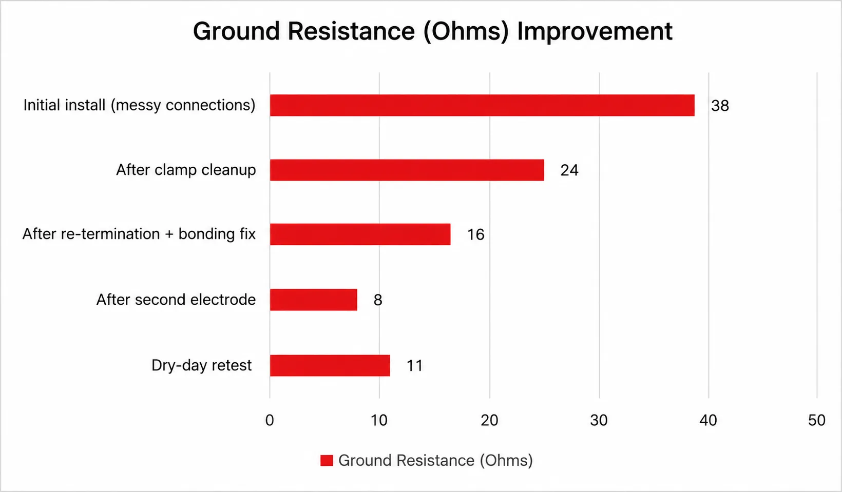
This chart taught me something important: one reading is a snapshot, not a verdict.
Soil moisture, contact quality, and test setup matter. Megger also emphasizes that earth resistance testing is not inherently complex, but interpreting results (and method limitations) is where people struggle.
For the latest available details, check the official page directly.
Earthing Systems and Grounding Mistakes I Made So You Don’t Have To
I made enough mistakes on this project to fill a training poster.
Here are the big ones:
- Mistaking bonding checks for earth resistance testing
- Assuming a lower number automatically means a safer system
- Treating all loads the same
- Considering a neutral-earth shortcut in a downstream panel
- Ignoring conductor routing and layout
- Testing once and declaring victory
The best correction I made was procedural:
- I documented the system
- I labeled PE and N bars clearly
- I grouped circuits by behavior
- I recorded measurements over time
- I had a qualified electrician review the final arrangement
That last step matters. Even if you’re experienced, fresh eyes catch dangerous assumptions.
If the insights you gained from electrical standards were intriguing and informative, exploring grounding best practices might be of great interest to you as well.
Earthing Systems and Grounding: Conclusion From a Real DIY Panel Upgrade
If I had to summarize this entire project in one sentence, it would be this:
Good earthing is not a single component—it is a system behavior.
I started this project thinking I needed a “better ground rod.”
What I actually needed was a better understanding of:
- which earthing system logic I was working within
- how PE and N should (and should not) be handled
- how TT, TN, and IT differ in fault behavior
- why TN-C/PEN concepts are not casual DIY shortcuts
- how to measure earth resistance properly and interpret results
The result was a workshop that feels safer, trips less, and behaves more predictably under mixed loads.
And honestly, the biggest win was confidence. Not overconfidence—the useful kind. The kind that comes from finally understanding why a system works.
FAQ on Earthing Systems and Grounding Measurements