








If you’d rather listen than read, feel free to play the audio file below for the rest of this article.
Selection Criteria for Electrical Measuring Instruments
Before choosing any electrical measuring equipment for a switchboard, the following criteria must be carefully evaluated to ensure accurate measurement, safety, and compatibility with the installation environment.
| Selection Criterion | Detail |
|---|---|
| Accuracy Class | 1.5, and if necessary 1 |
| Test Voltage | Example: 2000 V for 40–600 V operation |
| Quantity to Measure | Current, voltage, power, frequency, power factor, etc. |
| Installation Condition | Panel door, surface, flush, or internal mounting |
| Device Dimensions | 72×72 / 96×96 / 144×144 mm |
| Connection Method | Direct connection or via CT / PT |
If the information related to switchboard design was interesting and informative to you, researching pollution degree and overvoltage category concepts can be very engaging.
Powermeter — An Electronic Measuring Device for Multiple Parameters
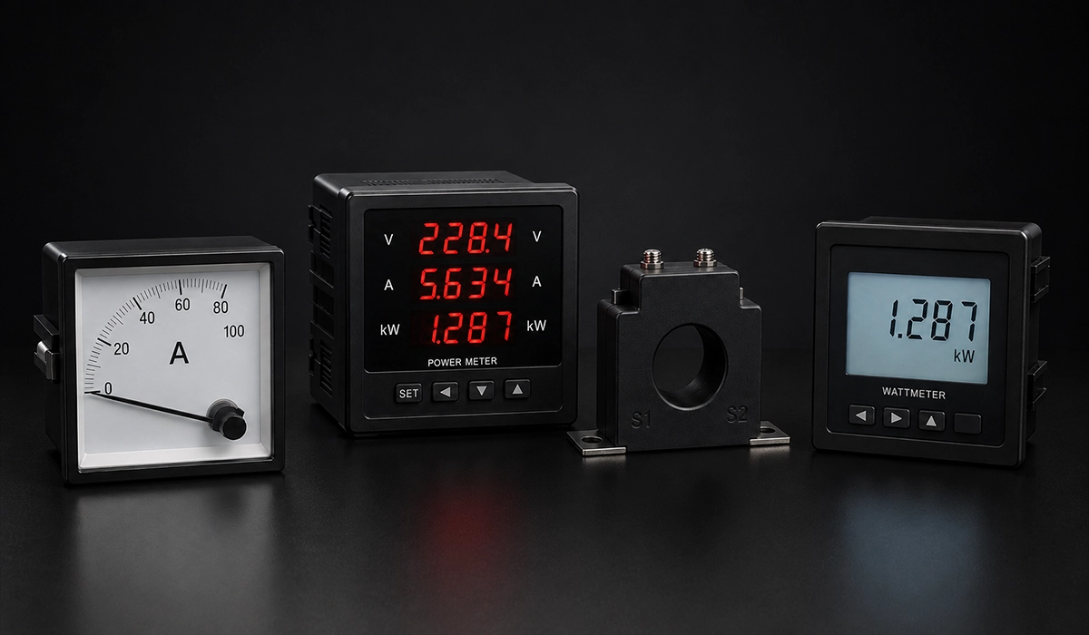
A powermeter is one of the most versatile electrical instruments on the market today. It is designed and manufactured to measure and calculate power, energy, active power, reactive power, power factor, current, and voltage. A panel powermeter, or power analyzer, is an electrical measuring instrument used to monitor multiple parameters related to power and energy in the electrical industry, large and small factories, industrial power operators, and single-phase and three-phase power transformer testing. Because it combines so many functions in a single unit, the powermeter is often the most efficient piece of information from an electronic measuring device available in a modern switchboard.
Ammeter — The Device Used to Measure Electric Current
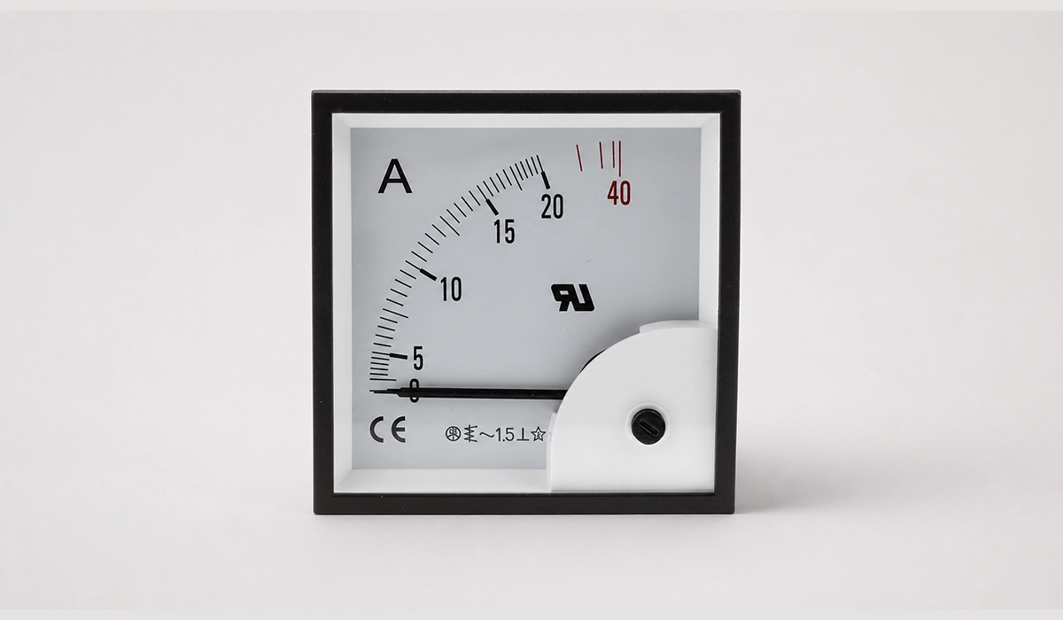
An ammeter is the most common device for measuring electric current in a circuit, and it is connected in series with the load. To measure the current passing through the load, the ammeter must be placed directly in series with it. To extend measurement range in low-power DC and AC circuits, parallel resistors (Rp), called an ammeter shunt, are used.
In switchboards, an ammeter can be installed to measure the current of each individual load, and a separate ammeter can be installed to measure total current. In a three-phase system with a balanced load, the current of one phase can be measured with a single instrument for measuring electric current and applied to the other two phases. However, since balanced loads are rarely placed directly on the main busbars of the board, one ammeter is typically used for each busbar — three ammeters in total.
Ammeters are available in two types: AC and DC. When using an ammeter, the circuit current must never exceed its rated or maximum value. For example, an ammeter rated 0–10 A only measures currents within that range. When the load current is higher than the ammeter’s range, or when the busbar cannot be connected directly, a current transformer (CT) is used instead. In a CT, the primary winding is the conductor or busbar itself, and the secondary is a coil.
Note that when using a current transformer, the transformation ratio must be applied to the value read on the ammeter — unless the ammeter’s scale has already been calibrated for the CT ratio, in which case the displayed number is the actual primary current and no additional calculation is required.
For three-phase low-current switchboards (under 100 A), the ammeter is connected directly (straight through, without a converter); for higher currents, it is connected via a CT. An ammeter is generally selected according to the circuit current plus roughly 20% margin — for example, a 60 A load in a low-voltage network would use a direct-connected ammeter, while higher currents are measured through a CT feeding the ammeter.
Ordering Specifications for an Ammeter
| Ordering Specification | Detail |
|---|---|
| Ammeter Size | 48×48, 72×72, 96×96, 144×144, 96×48 mm |
| Installation Method | Flush mounted (door) or Surface mounted |
| Accuracy Class | 0.5, 1, or 1.5 — lower number = higher accuracy |
| CT Ratio | CT ratio supplying the ammeter |
| Graduation | 1, 1.2, 2, 5, or 6 (use 5–6 for motor applications) |
| Needle Travel Angle | 90°, 180°, or 240° |
This “Graduation” characteristic can be 1, 1.2, 2, 5, or 6. In motor applications, because starting current can reach 5 to 6 times the rated current, a Graduation of 5 or 6 is required; in non-motor applications, 1.2 or 2 is typically sufficient. Some ammeters are equipped with a secondary needle that only moves from smaller values toward larger ones — this type is known as an ammeter with Max. Demand.
Voltmeter
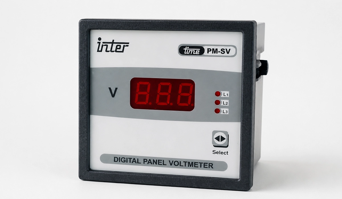
A voltmeter measures circuit voltage and is connected in parallel with the circuit. Like an ammeter, it is manufactured in AC and DC types. To extend measurement range in low-voltage single-phase circuits, series resistors (Rs) are used to increase internal resistance. To measure network voltage on a switchboard, the two terminals of the voltmeter are connected directly to the desired busbars — for example, phase R and neutral, or phases R and S. A volt selector switch is used when different phase-to-neutral or phase-to-phase voltages need to be measured.
Since voltmeters on standard switchboards typically measure one specific voltage with a small variation range (for example, 400 V phase-to-phase), their scales are compressed at the start and wider around the intended measurement range. Digital voltmeters, which display voltage numerically, are now very common.
To measure medium and high voltages, a voltage transformer (commonly 20 kV to 200 V) is used. In three-phase switchboards, a single voltmeter combined with a voltmeter switch (line key) can measure the voltage of each phase-to-neutral and phase-to-phase combination. Unlike an ammeter, a voltmeter’s Graduation is never 5 or 6 times the rated system voltage, since network voltage does not spike to that degree — a Graduation of 1.2 is usually sufficient.
In low-voltage networks, the switchboard voltmeter typically has a 0–500 V scale. In high-voltage control switchboards, the scale is based on network voltage, and the PT or CT transformation ratio is applied, with both primary and secondary voltages written on the voltmeter.
For a comprehensive understanding of wiring practices used alongside these instruments, we highly recommend reviewing this article on types of electrical wires and cables.
Frequency Meter
The frequency meter is another essential electrical measuring instrument. Electrodynamic, induction, and iron-ratio meters can function as frequency meters when combined with components such as inductors, capacitors, and resistors. Frequency meters are generally analog (needle type) but can measure across a wide range.
| Frequency Meter Type | Characteristics & Best Use |
|---|---|
| Vibrating (Reed) | High shock resistance, simple construction, low price — ideal for industrial switchboards |
| Needle Type | Wide measurement range — used in power plants and distribution substations |
| Digital | Highest accuracy, numerical display — widely used in modern installations |
| Synchroscope | Includes two frequency meters — used for synchronizing generators with the network |
Vibrating frequency meters are especially valued for their shock resistance and are widely used in switchboards for measuring low and medium frequencies. A vibrating frequency meter consists of metal blades placed side by side inside a coil, each with its own natural vibration frequency; when alternating current passes through the coil, the blade whose natural frequency matches twice the current’s frequency resonates and vibrates, indicating the frequency. A single-phase frequency meter operates at 230 V, and a three-phase unit at 400 V. The main application of a frequency meter is synchronizing (paralleling) two generators with the network.
Wattmeter
A wattmeter is used to measure the real (active) power of a load. It contains a current coil, connected in series with the load, and a voltage coil, connected in parallel — forming two separate circuits. Terminals for each coil are clearly marked, and care must be taken during wiring to avoid mistakes. While a wattmeter measures active power, a varmeter measures reactive power; both require current and voltage inputs. A wattmeter assembly consists of a galvanometer and a transducer.
In a balanced three-phase system, a single wattmeter is sufficient, since the power of one phase can be multiplied by three to obtain total three-phase power. For voltages and currents above the instrument’s rating, a voltage transformer and current transformer must be used.
Ordering Specifications for a Wattmeter or Varmeter
| Ordering Specification | Detail |
|---|---|
| Transformation Ratios | CT ratio and PT ratio must both be stated |
| Accuracy Class | Must be clearly specified by the user |
| Network Type | 3-phase 3-wire balanced / 3-phase 3-wire unbalanced / 3-phase 4-wire unbalanced |
| Galvanometer Specs | Size, installation method, full-scale deflection angle of needle |
| Transducer Output | 4–20 mA output if signal transmission to control room is needed |
Varmeter
The varmeter is an electrical measuring instrument that measures the reactive (non-useful) power of a circuit. Its wiring is similar to that of a wattmeter, and it is a standard part of the list of electrical measuring instruments found in industrial power monitoring panels. If the insights you gained from wattmeter and varmeter specifications were intriguing and informative, exploring IEC 61439 design verification and compliance might be of great interest to you as well.
Cosine Phi Meter (Power Factor Meter)
In factories and power plants where power factor must be closely controlled, a cosine phi meter is used. This electrical instrument has two moving coils and one fixed coil, with four or five connection terminals, and is used in both single-phase and three-phase circuits. A cosine phi meter — single-phase or three-phase — only displays the cosine phi of the phase its fixed coil is connected to. If a circuit’s power factor falls below the allowable limit, utility companies typically apply a financial penalty on the electricity bill.
Cosine phi meters for switchboard use are usually built for voltages of 110, 220, 380, and 500 V and currents of 5 A or 1 A. For higher voltages or currents, a voltage and current transformer must be added. In a balanced three-phase load, one cosine phi meter is sufficient; for unbalanced loads, a separate meter is used on each phase.
| Scale Type | Application |
|---|---|
| 90° One-Sided | Only inductive loads — value 1 (Cos φ) shown at scale end |
| 90° Two-Sided | Both inductive and capacitive loads — value 1 in the center, Ind and Cap on each side |
| 360° Rotating | Power plants and substations — Cos φ = 1 written twice with 180° difference |
Today, portable cosine phi meters — often with a digital seven-segment display — are widely used by companies that install capacitor banks for power factor correction, allowing the power factor of each phase to be checked independently.
Measuring Transformers
Since line current and voltage in power systems are too high to measure directly, measuring transformers are used to sample these quantities safely. Current transformers (CTs) are connected in series, while voltage transformers (PTs/CVTs) are connected in parallel within the circuit. These devices also isolate measuring and protection equipment from high-voltage networks and allow standardization of instruments for specific current or voltage ranges. In every measuring transformer, the sampled quantity must be reduced by a defined ratio, and the resulting error must stay within an acceptable tolerance.
If the information about Measuring Transformers was engaging and informative for you, gathering more knowledge about types of earthing systems could be very exciting.
Current Transformer (CT)
The primary winding of a current transformer is connected in series with the power circuit, while its secondary winding connects to measuring devices (meters) or protective devices (relays). The impedance connected to the CT secondary is very small compared to the primary impedance — in effect, the CT secondary operates in a near short-circuit condition. Proper insulation from primary network voltage and protection against overload are key features of these transformers.
The CT primary winding is marked with uppercase letters K and L, and the secondary with lowercase k and l; the primary must be wired so current enters at K. Current transformers are specified by their transformation ratio, such as 100/5.
| CT Specification | Detail |
|---|---|
| Primary Connection | In series with the power circuit |
| Secondary Connection | Connected to meters, relays, protection equipment |
| Secondary Rated Current | Often 5 A (e.g., 100 A / 5 A or 200 A / 5 A) |
| Terminal Markings | K (input) and L (output) — uppercase for primary |
| Safety Rule | Never use a fuse in the CT secondary supply path |
Voltage Transformer (PT)
When load voltage falls outside a voltmeter’s allowable range, or direct connection across the load isn’t possible, a step-down voltage transformer (PT) is used to measure voltage indirectly. The primary winding connects in parallel to the circuit, and the voltmeter connects to the secondary. The secondary voltage of a PT is typically 100 V, and — like a CT — its transformation ratio (Kv) is expressed as a fraction, such as 20 kV/100 V.
Voltage and Current Transducer
A transducer is fed from the secondary of a voltage or current transformer and produces a DC output in the milliampere range, allowing the signal to be transmitted long distances — for example, a 5 A CT secondary or 100 V PT secondary cannot practically be sent to a control room 500 meters away, but a transducer’s milliamp output can.
| Transducer Parameter | Detail |
|---|---|
| Input Source | Secondary of CT (5 A) or PT (100 V) |
| Output Signal | 4–20 mA DC (standard) or 0–20 mA |
| Output at Rated Input | 20 mA = rated input; 4 mA or 0 mA = zero input |
| Separate Power Supply | Required if output must show 4 mA at zero input |
| Transmission Distance | Up to 500 meters for control room signal transmission |
General Meter Specifications and Switchboard Design Notes
- Rated voltage, rated current, rated frequency, kWh revolution count, and type of power measured (active/reactive).
- If CTs or PTs supply measuring devices, ensure the supplied devices’ VA rating does not exceed the transformer’s rated VA.
- Never use a fuse in the CT secondary supply path.
- Each feeder line from the switchboard must be calculated independently.
- Key inputs for calculations: load power, nominal voltage, nominal current, nominal frequency, power factor, efficiency, network connection type (single-phase, three-phase, delta, star), distance from the switchboard, ambient temperature, conductor adjacency, and load simultaneity.
- Sub-panels are treated as loads relative to the main panel when sizing the main feeder cable.
- Protective equipment and operating methods influence the selection, number, and type of devices inside the panel.
- Equipment calculations use active power, except for capacitor panel calculations, which use reactive power.
- After gathering specifications for every outgoing line, a single-line diagram is drawn to determine required equipment per load and the total power drawn from the busbar and main breaker.
If the information about meter specifications and panel wiring was valuable and interesting to you, researching industrial control panel EMC requirements per IEC 61000 could be just as captivating.
Conclusion about Essential Electrical Measuring
The selection and integration of electrical measuring instruments — from basic ammeters and voltmeters to advanced powermeters and transducers — form the backbone of efficient industrial switchboard management. By carefully evaluating accuracy class, installation conditions, and the correct use of current or voltage transformers, engineers can ensure precise monitoring of critical parameters such as power factor, frequency, and real power. Understanding this full list of electrical measuring instruments, and knowing exactly which instrument is used to measure electric current, voltage, power, or frequency in a given application, is essential to building a safe, accurate, and long-lasting electrical infrastructure.
Finally, if you are looking for more information on enclosure ratings, it is recommended not to miss reading this article on IP55 vs Nm, bn EMA 12 ratings.


Rate this article
Choose a rating from 1 to 5 stars.
No ratings yet