

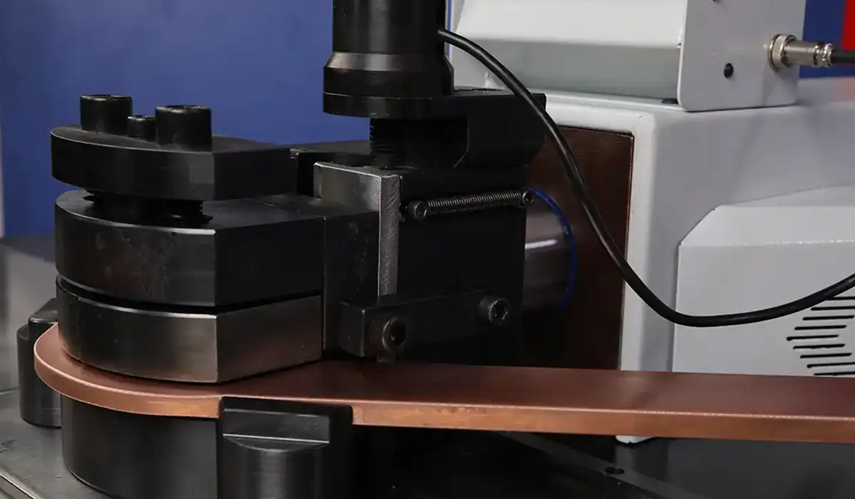

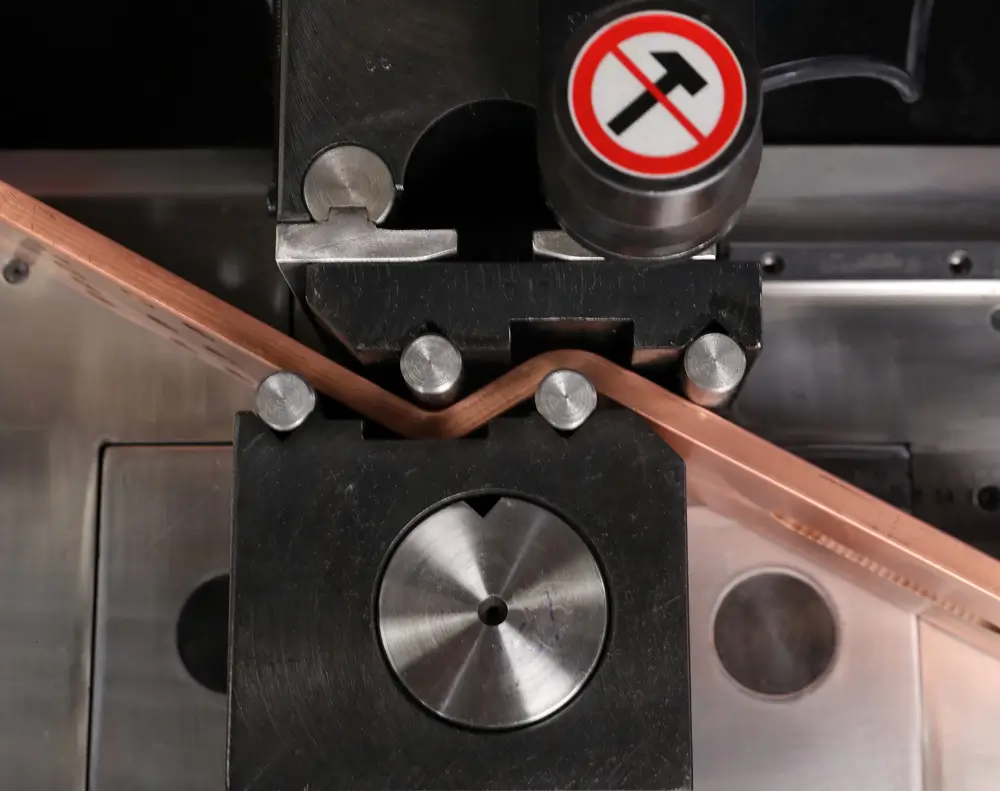
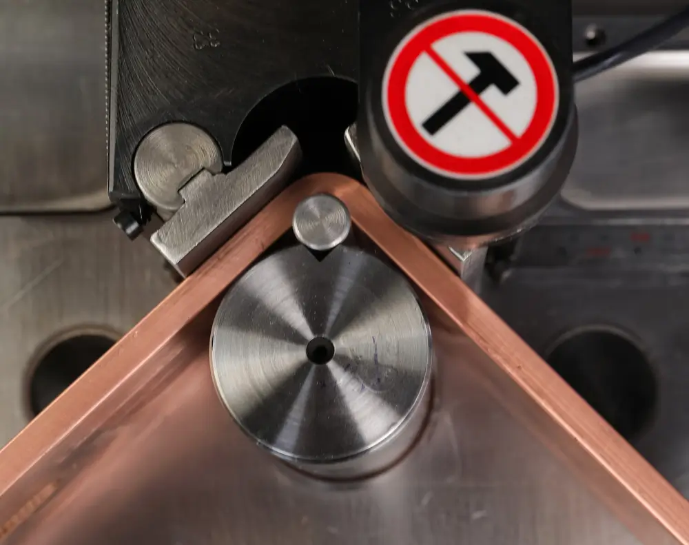
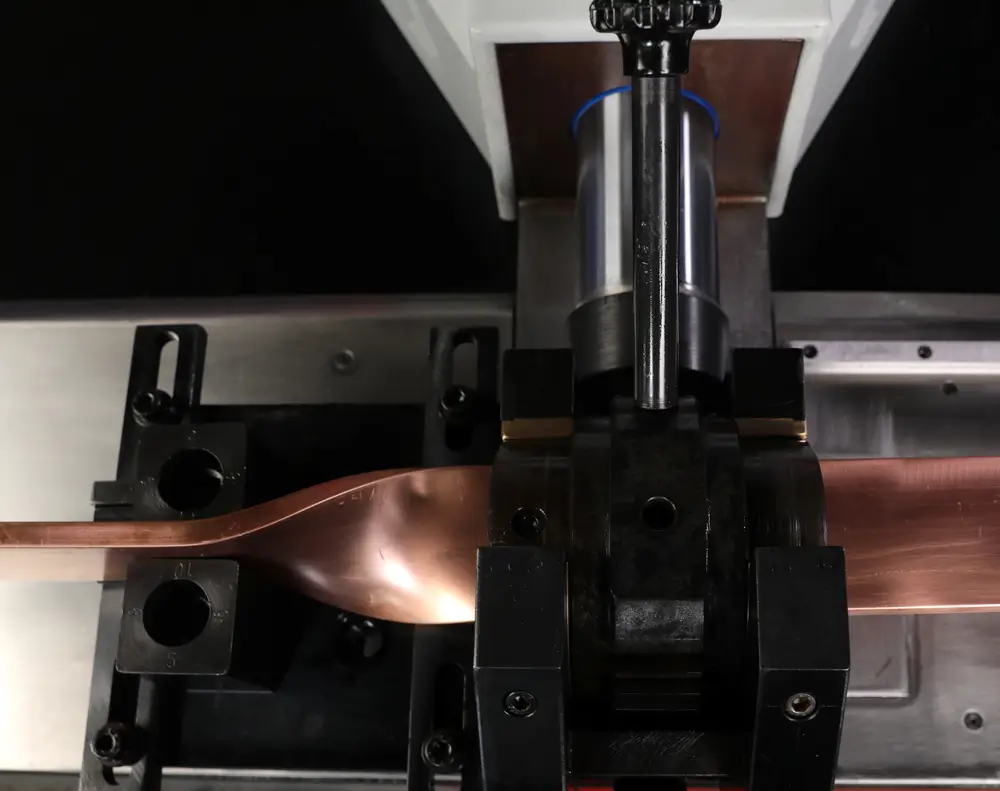
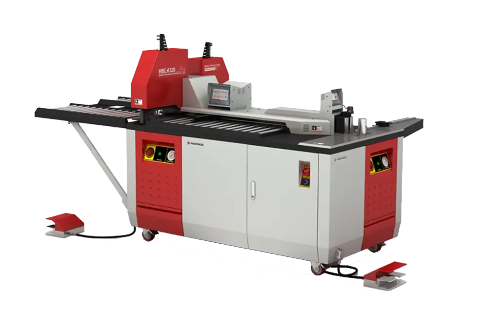
A busbar can look correctly bent on the workshop bench and still fail to fit properly inside an electrical panel. A small angle error, an offset in the wrong position or an unintended twist can leave connection faces misaligned and mounting holes out of position. The result is extra adjustment during assembly, unnecessary stress on terminals and supports, and avoidable rework.
Busbar bending accuracy means more than reaching a nominal angle. It means producing the finished geometry specified in the drawing: the correct angle, bend radius, bend position and orientation, with connection surfaces that fit their mating parts.
Why Small Bend Errors Become Assembly Problems
Inside a panel, a formed busbar must connect fixed points while passing around equipment and maintaining the specified distances from other conductors and the enclosure. Each bend affects where the next straight section ends up.
An angular error becomes more noticeable as the distance from the bend increases. For example, a 1-degree error over a 300 mm straight section produces approximately 5.2 mm of displacement at its end. This simplified example shows why a bend that looks acceptable by eye can leave a terminal connection noticeably out of position.
On parts with several bends, deviations can accumulate. Checking each angle separately is therefore not enough: the complete part must also meet its overall dimensions and connection positions.
Accurate Bends Help Connection Faces Align
A bolted busbar joint needs the intended overlap, suitable contact surfaces and the fastening arrangement specified for the assembly. Accurate forming helps bring those surfaces into their designed position before the bolts are tightened.
If a busbar reaches a terminal at the wrong angle, tightening the bolts to pull it into place can load the terminal and leave the conductor under mechanical stress. Depending on the joint geometry, misalignment can also interfere with the intended contact interface.
Connection bolts should secure a correctly fitted joint rather than compensate for an incorrectly formed busbar. If a part cannot be assembled within the specified fit-up requirements, investigate the dimensional error before tightening it.
Bending accuracy does not directly increase the electrical conductivity of copper or aluminium. Its electrical importance comes from helping preserve the designed arrangement and connection geometry. Joint performance still depends on surface preparation, fasteners, tightening procedures and the equipment manufacturer’s instructions.
Correct Geometry Helps Maintain Electrical Clearances
A misplaced bend can move a live conductor closer to another phase, an earthed mounting plate or the metal enclosure. This is particularly relevant where several busbars pass through a compact compartment.
The finished assembly must maintain the clearances and creepage distances required by its design and applicable standards. Those requirements depend on factors such as voltage, insulation arrangements and environmental conditions; there is no single spacing value suitable for every panel.
Accurate forming helps reproduce the intended conductor route, but it does not replace inspection of the installed assembly. Check distances after mounting, including around bends, bolt heads, supports and insulating barriers.
Bend Radius Matters as Much as Bend Angle
A correct angle does not make a bend acceptable if the radius is unsuitable. An excessively tight radius can damage the material, while an unnecessarily large radius can prevent the part from fitting its intended space.
The appropriate internal bend radius depends on the material grade, temper, thickness and bending direction. Copper and aluminium should not automatically be formed using the same settings, and a setting proven on one material condition may not suit another.
- Use suitable tooling: match the forming tool to the required geometry and the material being processed.
- Follow the specified radius: use the drawing and relevant material guidance rather than a universal rule of thumb.
- Inspect the formed area: check for cracks, unacceptable distortion and surface damage.
- Avoid repeated corrective bending: repeated deformation can work-harden the material and increase the risk of damage.
Springback Changes the Finished Angle
After the forming force is removed, the busbar recovers part of its elastic deformation. This springback means the angle under load may differ from the final, unloaded angle.
The amount of recovery depends on material properties, bar dimensions, tooling and the forming process. A single correction value should not be assumed to work for every batch of copper or aluminium.
Measure the first part after unloading and adjust the process using the equipment’s supported controls. Where angle measurement or springback compensation is available, verify its result on the actual material being processed.
The acceptance check should use the finished, unloaded part. A repeatable machine setting is useful only when it produces geometry within the specified tolerance.
Bend Position and Hole Alignment Must Work Together
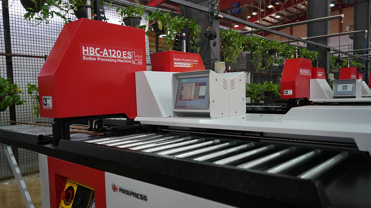
Busbar accuracy depends on the relationship between cutting, punching and bending. A correctly formed angle can still leave the part unusable if the bend starts in the wrong position or the connection holes were located using an inconsistent reference.
Use defined datums throughout fabrication and account for bend allowance when establishing the flat blank. Confirm that the process sequence and tooling access suit the part, especially where holes or connection faces are close to a bend.
For the wider cutting, punching and bending workflow, explore the Busbar Fabrication Machine range.
A CNC busbar machine can support repeatable cutting and hole positioning within its specified capabilities. The subsequent bending operation must still reference those features correctly and meet the finished-part drawing.
Good Fit Reduces Stress on Terminals and Supports
A busbar should fit its intended mounting points without being forced into an unintended shape. Pulling a misaligned conductor into position can impose loads on terminal assemblies, insulators and supporting hardware.
The assembly must also accommodate the thermal expansion and mechanical loading considered in its design. Accurate fabrication helps reproduce that design; it does not independently establish short-circuit withstand capability or replace verification of the support system.
During assembly, check that the busbar seats as intended and that its supports and connections can be secured using the specified procedure.
Repeatable Forming Reduces Panel Assembly Rework
When nominally identical busbars arrive with different angles or offsets, assemblers must investigate and adjust each one. This slows production and makes interchangeable parts harder to achieve.
Consistent forming allows a proven part geometry to be repeated across a batch. It can reduce trial fitting, replacement parts and unnecessary handling, provided that tooling condition, material variation and inspection remain under control.
For workshops using Busbar machines, the useful measure is not simply how quickly a bend is made. It is how consistently the complete part meets its drawing and fits the panel without corrective work.
What to Check Before Installing a Formed Busbar
Inspect the first part before releasing a production batch, then apply checks at intervals appropriate to the process and its risks. Recheck the setup after changes to material, tooling or relevant machine settings.
- Final bend angle: measure after the forming force has been removed.
- Bend position and overall dimensions: confirm the location of each bend and the finished connection points.
- Internal bend radius: verify that it meets the drawing and material requirements.
- Hole alignment and contact-face orientation: confirm fit against the mating parts or a suitable inspection fixture.
- Unintended twist and distortion: check that straight sections and connection faces remain correctly oriented.
- Material and surface condition: inspect for cracks, burrs and unacceptable damage to the conductor or coating.
- Installed fit and spacing: verify support alignment and the required distances within the completed assembly.
Set acceptance tolerances from the approved drawing and assembly requirements. A single angle tolerance is not suitable for every busbar: long sections and closely constrained connections may need tighter control than shorter, less constrained parts.
Use Professional Bending Equipment for Better Process Control
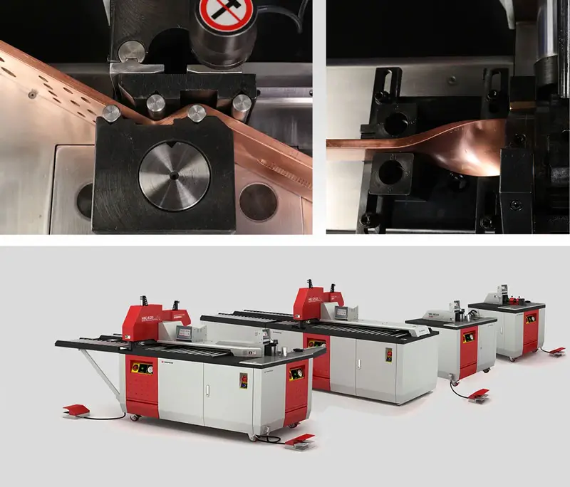
If you want more consistent bending accuracy in regular panel production, we recommend investing in a professional busbar bending machine matched to your material, maximum bar dimensions and required bend shapes. Suitable tooling, stable positioning and appropriate controls make it easier to establish and repeat a verified setup.
Compare the available models and control options against your actual parts. Equipment selection should consider the required finished-part tolerances as well as capacity; machine power alone does not establish bending accuracy.
Accurate Bends Make Better-Fitting Busbars
Busbar bending accuracy matters throughout panel assembly: it helps connections align, maintains the intended conductor route and reduces corrective work. Getting it right requires suitable bend radii, controlled springback and inspection of the finished geometry. With precise equipment, appropriate tooling and a verified setup, manufacturers can produce busbars that fit consistently and support the panel’s intended electrical and mechanical design.



Rate this article
Choose a rating from 1 to 5 stars.
No ratings yet