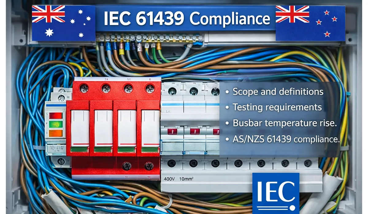


The Foundation: What Makes IEC 61439 Different from Older Standards
IEC 61439 represents a shift from prescriptive rules to performance-based engineering. Rather than dictating every construction detail, the standard gives panel builders three equally valid pathways to prove conformity: direct testing, comparison with a reference design, or calculation using validated methods.
This flexibility means smaller shops can compete with large manufacturers, provided they document their verification choices properly. The standard applies to assemblies up to 1000 V AC or 1500 V DC and covers everything from household distribution boards to industrial motor control centers.
For those seeking comprehensive information on electrical standards governing switchgear equipment, exploring standards for switchgear provides essential foundational knowledge.
The IEC 61439 Family: Seven Parts, One Base, Many Applications
IEC 61439-1 provides the general rules that apply to all assembly types. Every panel builder and design engineer must master Part 1 before working with any specific application part. Part 1 covers definitions, service conditions, construction rules, and the verification framework.
The product-specific parts then add their own requirements:
| Part | Title | Typical Application |
|---|---|---|
| IEC 61439-1 | General Rules | Base rules for all assembly types |
| IEC 61439-2 | Power Switchgear & Controlgear Assemblies | Main LV distribution, MCCs |
| IEC 61439-3 | Distribution Boards | Residential and commercial distribution |
| IEC 61439-4 | Assemblies for Construction Sites | Temporary power and site supplies |
| IEC 61439-5 | Public Network Distribution Assemblies | Utility-grade distribution |
| IEC 61439-6 | Busbar Trunking Systems | Rising mains and busway |
| IEC 61439-7 | Assemblies for Specific Applications | Marinas, camping sites, marketplaces, EV charging, and similar use cases |
The choice of part depends entirely on your assembly’s end-use environment, who will operate it, and what duty it must perform. A motor control centre in a factory follows Part 2. A distribution board in an apartment building follows Part 3. Each part adds specifics that the general rules alone do not address.
The full reference document is available for download to support your research.
Design Verification vs Routine Verification: Two Different Jobs
The most common mistake panel builders make is treating design verification as an optional extra. In reality, design verification and routine verification serve completely different purposes and neither can replace the other.
Design verification happens once per design. It answers the question: “Does this design meet the standard?” You test a sample, compare it to a reference design, or calculate its performance. You document your evidence. Once verified, that design can be built repeatedly.
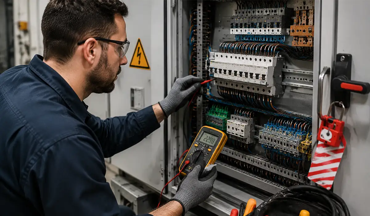
Routine verification happens every single time you manufacture an assembly. It answers the question: “Does this specific unit match the verified design?” You inspect workmanship, test continuity, check dielectric strength, and verify mechanical function. These checks protect your reputation and catch assembly errors before they reach the customer.
| Aspect | Design Verification | Routine Verification |
|---|---|---|
| Frequency | Once per design or relevant design change | Every single assembly produced |
| Purpose | Prove the design complies | Confirm each unit matches the design |
| Main owner | Original manufacturer or assembly manufacturer | Assembly manufacturer |
| Methods | Testing, derivation, calculation, design rules | Inspection and factory testing |
| Record | Design verification report | Routine verification record |
Download this resource to compare the details more easily during your review process.
Three Paths to Prove Your Design Works
IEC 61439 does not force you down one verification path. Instead, it recognizes that different designs need different evidence. Larger manufacturers may choose full testing. Small shops may use comparison or calculation. The standard requires only that your chosen method produces adequate proof.
This article serves as a valuable resource for those seeking detailed information on IEC 61439 Designs Verification.
Path 1: Physical Testing at an Accredited Laboratory
Testing delivers the strongest evidence. An independent laboratory subjects your assembly to heat-rise tests, short-circuit tests, dielectric tests, mechanical tests, and IP protection tests. The resulting type test report (TTR) becomes your golden reference for future similar designs.
Testing works best when you build the same design repeatedly or when you need to establish a new platform. It costs more upfront but saves time on project-specific verification.
Download the complete reference material to support your planning, analysis, or procurement process.
Path 2: Proven Similarity to a Reference Design
Derivation (comparison) uses a previous test result to justify a similar design. If the original manufacturer published limits for busbar current, fault level, device types, and enclosure construction, you can build variants inside those limits without re-testing.
The critical rule: stay inside the envelope. Exceed a single limit, and you lose the protection of the reference. You must then verify that changed parameter by testing or calculation.
You can download the full report here to review the topic in greater detail.
Path 3: Calculated Proof Using Documented Methods
Engineering calculations and design rules allow you to verify performance without testing. Temperature rise can be calculated from conductor losses and enclosure ventilation. Clearance and creepage distances come from standard tables. Short-circuit forces can be derived from circuit parameters.
This method requires rigorous documentation. Every assumption—ambient temperature, diversity factor, material properties, installation altitude—must be recorded so an auditor can follow your logic.
Download the attached file to explore the complete data and supporting information.
What Must Be Verified: Constructional and Performance Characteristics
IEC 61439-1 Clause 10 lists everything that must be verified. The standard divides these into constructional characteristics (how it is built) and performance characteristics (how it behaves under load and fault).
Constructional Characteristics: Building the Right Assembly
These checks verify that your assembly is mechanically sound and properly protected against hazards:
– Material strength and durability
– Degree of protection (IP rating) against dust and water ingress
– Clearances and creepage distances for electrical safety
– Protection against accidental electric shock
– Correct integration of switching devices and control equipment
– Internal wiring conformity and terminal connections
– Proper terminals for field wiring connections
Each of these can be verified by inspection, measurement, or visual check against the approved design.
For a comprehensive understanding of IP55 vs NEMA 12, we highly recommend reviewing this article.
Performance Characteristics: Operating Within Safe Limits
These checks confirm that your assembly behaves safely under normal and fault conditions:
– Dielectric insulation strength (withstanding voltage spikes)
– Temperature rise under rated load (thermal stability)
– Short-circuit withstand strength (mechanical and thermal stability during faults)
– Electromagnetic compatibility (EMC) with surrounding equipment
– Mechanical operation (doors, interlocks, withdrawable units functioning correctly)
Heat Management: Temperature Rise and the Diversity Factor Concept
One of the most misunderstood topics in IEC 61439 is thermal verification. Panels generate heat from conductor losses and device dissipation. This heat must be managed so that no part exceeds temperature limits.
The standard introduces the Rated Diversity Factor (RDF), which acknowledges that not every circuit in a panel draws full rated current simultaneously. If you have a 10-circuit panel with 100 A circuits, applying RDF = 0.7 assumes only 70% of the total capacity is in use at once.
This realistic approach saves enclosure space and cost while maintaining safety. However, the RDF must be agreed with the end user and documented. Defaulting to RDF = 1.0 leads to unnecessary oversizing.
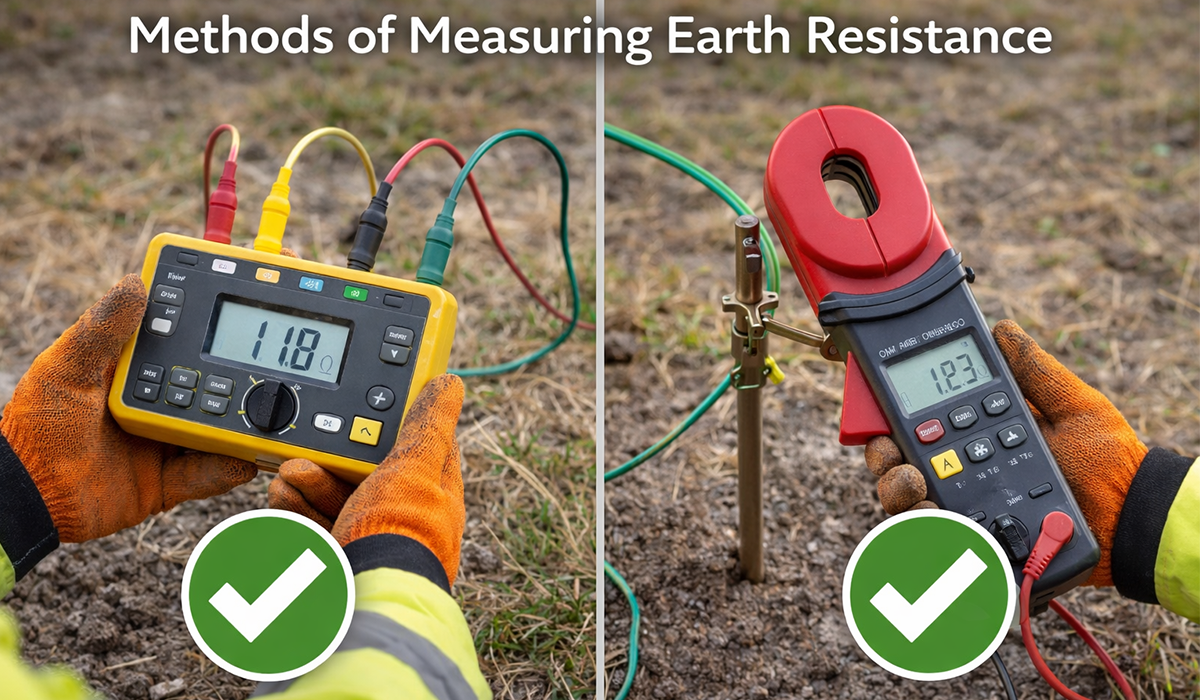
Temperature verification can be done by testing the assembly under rated conditions or by calculation using validated thermal models. If you add components later, you must recalculate or re-test.
Save this downloadable resource for quick access whenever you need it.
Short-Circuit Strength: Three Parameters You Must Know
When a fault occurs, the assembly must withstand extreme electrical and mechanical stresses. IEC 61439 requires verification of three short-circuit parameters:
**Icw** (Thermal short-time withstand current): The assembly must survive a fault lasting 1 or 3 seconds without thermal damage. This tests busbar strength, support rigidity, and device heating limits.
**Ipk** (Peak withstand current): The assembly must survive the first half-cycle of a fault without mechanical deformation. This tests the mechanical strength of busbars and supports against the violent electromagnetic forces.
**Icc** (Conditional short-circuit current): When protective devices (circuit breakers or fuses) limit fault current below the assembly’s withstand rating, the assembly is protected by those devices. This allows verification without destructive testing.
IEC 61439-2 short-circuit withstand verification methods cover Icw, Ipk, and conditional short-circuit current. The builder must check the busbar system, incoming section, outgoing circuits, supports, and protective device coordination.
Derivation works only when the final configuration remains inside the original manufacturer’s test envelope. Auditors often find non-conformance where builders increase current rating or fault level without fresh evidence.
Further exploration of short-circuit withstand can be found in the following recommended reading.
Insulation Distances: Air Gaps and Surface Creepage
Electrical safety depends on preventing arcs and tracking. IEC 61439 uses two distance measurements, both defined in IEC 60664-1:
**Clearance** is the shortest air path between two conductive parts at different potentials. Higher voltages require larger clearances. For example, an 8 kV impulse voltage requires 8 mm minimum clearance.
**Creepage** is the shortest surface path along insulating material. This distance depends on the material’s resistance to tracking, the pollution level in the environment, and the material group rating (CTI).
When assessing creepage and clearance requirements, understanding pollution degree concepts becomes essential for accurate design verification.
| Rated Impulse Voltage (Uimp) | Typical Minimum Clearance in Air |
|---|---|
| 2.5 kV | 1.5 mm |
| 4 kV | 3.0 mm |
| 6 kV | 5.5 mm |
| 8 kV | 8.0 mm |
Use the official tables for the final design. Pollution degree and material group often drive creepage more directly than clearance.
Enclosure Protection Rating (IP): More Than Just Numbers
The IP code (e.g., IP54, IP65) tells users what the enclosure protects against. Typical industrial panels are IP54 (dust protection, water splash protection). Outdoor or washdown areas need IP65 (dust-proof, water-jet proof).
But here is the catch: the IP rating applies to the complete assembly, not just the empty enclosure. When you drill cable entry holes, install glands, add ventilation fans, or cut access doors in the field, you must ensure the modified assembly still meets the declared IP rating.
For comprehensive guidance on protection degree ratings and their practical application in panel design, reviewing IP degree of protection standards is highly recommended.
Therefore, the panel builder must assess modifications, not only the empty enclosure certificate. When the workshop drills new holes or adds ventilation grilles, it should document how the final assembly still meets the declared IP code.
You can get the complete file here and use it as a practical working reference.
Building Your Compliance File: Documentation That Protects You
Compliance without documentation is compliance nobody can prove. IEC 61439 requires that you keep records showing how you verified the design and how you checked each manufactured unit.
For industrial control panels, proper CE marking compliance requires thorough documentation and rigorous compliance verification processes.
Your technical file should include:
– Design verification reports (tests, calculations, or comparison data)
– Routine verification records for every shipped assembly
– Electrical diagrams and terminal schedules
– Component schedules listing every device, its rating, and its manufacturer
– Certificates of conformity from component suppliers
– Your own declaration of conformity signed by a responsible person
– Label samples and nameplate information
– Risk assessments and design notes
Keep this file complete and accessible. If a customer disputes a panel’s ratings or an authority requests proof of compliance, your file must answer their questions clearly. Incomplete or missing records can invalidate your CE marking.
For offline reading, you can download the complete document from this link.
Roles and Responsibilities: Who Does What
IEC 61439 draws a clear line between the original manufacturer (who designs the base system) and the assembly manufacturer (who builds the final panel). Understanding this split prevents confusion and ensures nobody abdicates responsibility.
Reference: Hensel IEC/EN 61439 Guide — Explains original manufacturer and panel builder responsibility split.
The original manufacturer publishes design limits and test data. They may provide modules, busbar enclosures, or switchgear frames that have been tested to known limits. Panel builders use this data to configure custom assemblies.
But here is the critical point: the assembly manufacturer remains responsible for verifying that the final configuration meets the standard. A type test report from the original manufacturer does not automatically certify your finished panel. You must verify your specific application.
| Responsibility | Original Manufacturer (OM) | Assembly Manufacturer (AM) |
|---|---|---|
| Type testing core systems | Yes | No, unless acting as OM |
| Reference design data | Provides | Uses and validates limits |
| Design verification of final assembly | Supports | Owns entirely |
| Routine verification of each unit | Not applicable | Mandatory |
| Declaration for final product | Not applicable | Issues and retains |
Red Flags: Common Failures Found in Audits
Compliance audits and customer reviews often uncover the same preventable mistakes. These are the errors that damage reputation and invite legal liability:
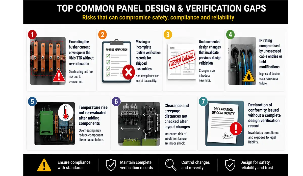
Exceeding the busbar current envelope in the OM’s TTR without re-verification— You used a reference design rated for 400 A but specified 500 A in your panel. This change voids the derivation path.
Missing or incomplete routine verification records for shipped assemblies — You tested the first unit but not the 50 others sent to the customer. Routine checks must happen on every assembly.
Undocumented design changes that invalidate previous design validation — You changed the enclosure size, added a device, or modified ventilation but did not re-verify temperature rise.
IP rating compromised by unassessed cable entries or field modifications — The enclosure is IP54, but cable glands were installed incorrectly or the door seal deteriorated.
Temperature rise not re-evaluated after adding components — The original design had margin, so adding one more device seemed safe. It was not verified.
Clearance and creepage distances not checked after layout changes— The busbar arrangement was redesigned for manufacturability, but insulation distances were not rechecked.
Declaration of conformity issued without a complete design verification record — You signed the CE declaration but the design file contains only a copy of a supplier’s component datasheet, no actual verification.
Use the list below as a quick panel builder compliance checklist during design review, production release, and final quality inspection. It works best when teams review it before shipping, not after a client complaint.
Further exploration of High Voltage Testing can be found in the following recommended reading.
- Exceeding the busbar current envelope in the OM’s TTR without re-verification
- Missing or incomplete routine verification records for shipped assemblies
- Undocumented design changes that invalidate previous design validation
- IP rating compromised by unassessed cable entries or field modifications
- Temperature rise not re-evaluated after adding components
- Clearance and creepage distances not checked after layout changes
- Declaration of conformity issued without a complete design verification record
Making IEC 61439 Work in Your Shop
IEC 61439 compliance is not bureaucracy. It is engineering discipline applied to safety and reliability. When you verify a design systematically, you catch problems before they reach the customer. When you test every assembly, you ensure consistent quality. When you document your choices, you can prove compliance and defend your reputation.
The pathway is clear: define your assembly type and applicable part. Choose your verification method based on cost, schedule, and risk. Execute that method rigorously. Document every decision. Then verify routine production. This workflow protects you, your customers, and the end users who depend on your panels.
This approach helps teams build stronger evidence under the current EN 61439 and BS EN 61439 framework and delivers both safety and commercial control. Panel builders who adopt this discipline gain market credibility, simplified CE marking, and improved long-term reliability.
That discipline improves safety and commercial control. It also protects delivery schedules because teams resolve compliance questions before procurement, fabrication, testing, and site commissioning.
This article serves as a valuable resource for those seeking detailed information on AS/NZS 61439 vs IEC 61439.