
Electrical switchgear is a collective term for all equipment used to switch, control, protect, and isolate electrical circuits and apparatus in a power system. To answer what is the basic purpose of electrical switchgear directly: it serves three inseparable functions — circuit protection, power switching, and fault isolation. Switchgear exists at every voltage tier, from low-voltage distribution panels in commercial buildings to high-voltage assemblies in transmission substations. For a broader foundation, see switchgear basics, explore switchgear secrets, and review modern switchgear. Governed internationally by IEC 62271 and in North America by the ANSI/IEEE C37 series, it forms the protective and operational backbone of every modern electrical network.
Prefer listening? You can play the audio version of the rest of this article below.
The Three Core Functions of Electrical Switchgear
Understanding what is the basic purpose of electrical switchgear requires examining each of its three core functions in context. The purpose of electrical switchgear in power distribution rests on this interdependent triad: protection, control, and isolation. Each function is essential; none can be removed without compromising the integrity and safety of the entire power system. A practical overview of related systems appears in panel pioneers.
For a comprehensive understanding of Electrical Panel, we highly recommend reviewing this article.
Protection involves detecting abnormal operating conditions — overcurrent, short-circuit, and earth fault — and automatically isolating the faulty section using protective relays and circuit breakers before damage propagates to healthy parts of the network. A medium-voltage switchgear board in a manufacturing plant, for example, reacts to a line fault in milliseconds. For device selection, check breaker finder.
Control enables both operators and automatic systems to switch circuits on or off for load management, planned maintenance, and real-time grid balancing. Modern intelligent electronic devices (IEDs) embedded within switchgear panels also provide continuous power quality monitoring, metering, and disturbance recording.
Isolation provides a verified, visible break in the circuit, ensuring that maintenance technicians work on fully de-energized equipment. This function is directly mandated by OSHA 29 CFR 1910.147 lockout/tagout requirements, which require positive confirmation that hazardous energy has been controlled before any work commences.
Switchgear as a Protective Device: Circuit Isolation and Fault Clearing
How does electrical switchgear protect industrial circuits from faults? Protective relays — identified by ANSI device numbers such as 50/51 for overcurrent protection and 87 for differential protection — detect fault conditions and initiate circuit breaker tripping. The breaker’s interrupting rating, expressed in kiloamperes symmetrical (kA sym), must always exceed the available fault current at the point of installation to guarantee safe fault clearing.
For a comprehensive understanding of GE breakers, we highly recommend reviewing this article.
Selective coordination ensures that only the circuit breaker nearest to a fault operates, minimizing supply disruption to healthy feeders. Current-limiting fuses within switchgear assemblies further reduce let-through fault energy and incident energy exposure, directly supporting arc flash mitigation objectives across the installation. You can also compare protective options with arc fault.
Reference: ANSI/IEEE C37.20.1 — Metal-Enclosed Low-Voltage Power Circuit Breaker Switchgear — IEEE standard defining interrupting ratings, construction requirements, and selective coordination principles for LV switchgear assemblies.
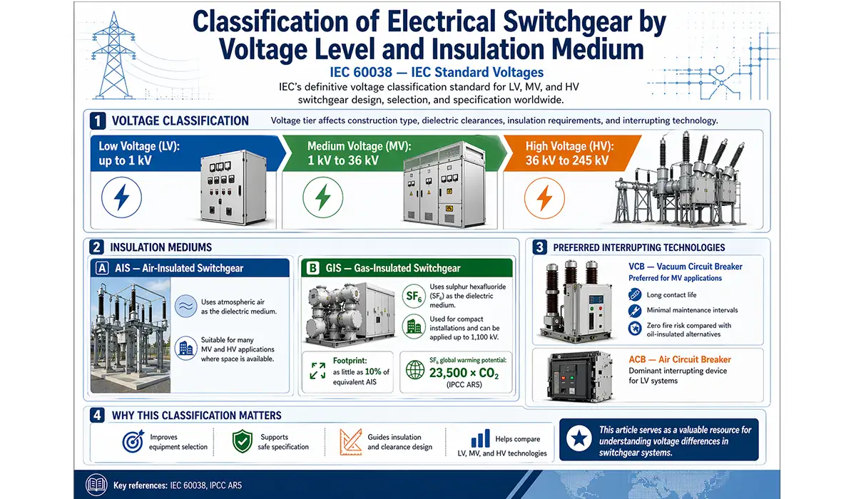
Classification of Electrical Switchgear by Voltage Level and Insulation Medium
IEC 60038 — IEC Standard Voltages — IEC’s definitive voltage classification standard establishing the LV, MV, and HV boundaries applied in switchgear design, selection, and specification worldwide.
Low voltage vs medium voltage vs high voltage switchgear classification follows IEC 60038 boundaries: LV up to 1 kV, MV from 1 kV to 36 kV, and HV from 36 kV to 245 kV. Voltage tier is not merely a label — it determines construction type, dielectric clearance distances, insulation requirements, and the appropriate interrupting technology for each assembly.
Air-insulated switchgear (AIS) uses atmospheric air as the dielectric medium and remains suitable for the majority of MV and HV applications where physical space is not constrained. Gas-insulated switchgear (GIS), by contrast, employs sulphur hexafluoride (SF₆) — a gas with a global warming potential of 23,500 relative to CO₂ per IPCC AR5 — enabling installations up to 1,100 kV in a footprint as little as 10% of equivalent AIS.
Vacuum circuit breakers (VCBs) have become the preferred interrupting technology for MV applications, offering long contact life, minimal maintenance intervals, and zero fire risk compared to oil-insulated alternatives. Air circuit breakers (ACBs) serve as the dominant LV interrupting device.
This article serves as a valuable resource for those seeking detailed information on voltage differences.
Table 1: Keyword Research Matrix
| KEYWORD TYPE | EXAMPLE KEYWORD | SEARCH INTENT | EST. COMPETITION |
|---|---|---|---|
| Short-Tail (Primary) | Electrical switchgear | Informational | Very High |
| Mid-Tail | Purpose of electrical switchgear | Informational | Medium |
| Long-Tail (Main) | What is the basic purpose of electrical switchgear? | Informational | Low–Medium |
| LSI | Power distribution protection system | Informational | Low |
| Buyer Intent | Buy medium voltage switchgear | Transactional | High |
| Industry-Specific | HV switchgear in electrical substations | Commercial | Medium |
Table 2: Switchgear Types — Voltage Range, Purpose & Application
| SWITCHGEAR TYPE | VOLTAGE RANGE | PRIMARY PURPOSE | TYPICAL APPLICATION |
|---|---|---|---|
| Low Voltage (LV) | Up to 1 kV | Building-level protection & distribution | Commercial buildings, factories |
| Medium Voltage (MV) | 1 kV – 36 kV | Industrial & utility feeder control | Industrial plants, substations |
| High Voltage (HV) | 36 kV – 245 kV | Transmission network switching | Grid substations, power plants |
| Gas Insulated (GIS) | Up to 1,100 kV | Compact HV switching in confined spaces | Urban substations, offshore platforms |
Role of Electrical Switchgear in Power Distribution and Substations
What is the role of electrical switchgear in power distribution systems? In substation architecture, switchgear forms the primary switching and protection layer, positioned between incoming power transformers, busbars, and outgoing distribution feeders. Engineers represent this relationship in a single-line diagram (SLD), where the switchgear position defines the protection boundary for each circuit section.
Further exploration of busbar systems can be found in the following recommended reading.
Busbar configurations directly determine supply reliability. A single-bus arrangement is simple and cost-effective but offers no redundancy. Double-bus, ring-bus, and breaker-and-a-half schemes each progressively increase reliability trade-offs at higher capital cost, with the breaker-and-a-half configuration providing maximum redundancy for critical transmission applications.
Modern switchgear increasingly incorporates IEC 61850 communication protocols, enabling real-time SCADA connectivity and digital substation functionality. This replaces conventional copper secondary wiring with fiber-optic Ethernet, reducing installation complexity and vastly expanding data granularity for event recording and fault analysis.
Distributed energy resource (DER) interconnection — including grid-tied solar arrays and wind generation — relies on purpose-designed protective switching assemblies for islanding protection, anti-islanding detection, and safe synchronization with the utility grid, making modern switchgear a key enabler of the energy transition.
Switchgear in Industrial Settings: Purpose in Manufacturing and Process Plants
The purpose of medium voltage switchgear in industrial power networks extends well beyond simple fault interruption. In oil and gas, petrochemical, mining, data center, and heavy manufacturing environments, switchgear selection directly governs power system reliability indices — specifically SAIDI (System Average Interruption Duration Index) and SAIFI (System Average Interruption Frequency Index). Unplanned industrial shutdowns cost the U.S. manufacturing sector over $50 billion annually (Deloitte, 2016), giving proper switchgear specification a direct commercial value. For panel design context, review panel components.
Switchgear protection systems in industrial settings must integrate tightly with motor control centers (MCCs). While MCCs manage individual motor starting and protection at the load level, upstream switchgear provides feeder-level fault clearing and the selective coordination essential to limiting production downtime during fault events.
Zone-selective interlocking (ZSI) is a distinguishing feature in industrial LV switchgear. ZSI enables upstream and downstream breakers to communicate via a hardwired signal, ensuring that only the breaker nearest to a fault trips — significantly reducing arc flash incident energy and minimizing equipment damage.
Hazardous area installations demand Ex-e (increased safety) and Ex-d (flameproof) rated enclosures certified to ATEX and IECEx standards for Zone 1 and Zone 2 classified locations. Manual vs automatic switching strategies must also be reviewed in these environments to prevent ignition of flammable atmospheres.
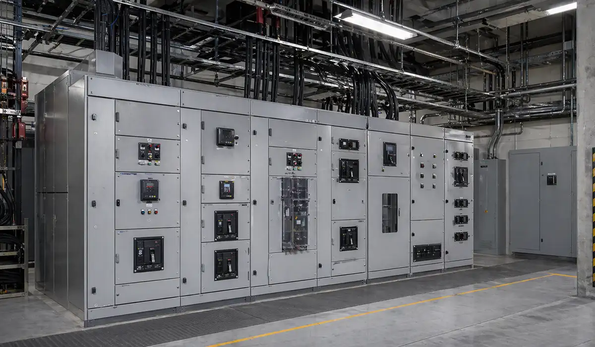
Key Components Inside an Electrical Switchgear Assembly
Electrical switchgear functions and components are best understood through the internal anatomy of a metal-clad MV panel. Circuit breakers — vacuum circuit breakers (VCBs) for MV, air circuit breakers (ACBs) for LV, and molded case circuit breakers (MCCBs) for feeder sub-distribution — form the primary current-interrupting elements. Each is selected against fault current level, rated continuous current, and breaking capacity.
Disconnect switches and earthing switches provide visible isolation and positive grounding, confirming to maintenance teams that all conductors are safely de-energized before any work commences. This visible break is distinct from the circuit breaker’s primary interrupting function.
Current transformers (CTs) and voltage transformers (VTs) scale primary current and voltage to standardized secondary levels (typically 5 A and 100–110 V respectively), feeding numerical protective relays and revenue-grade metering. Electromechanical relays have been largely replaced by numerical (microprocessor-based) IEDs in modern assemblies, offering superior flexibility and self-monitoring capability.
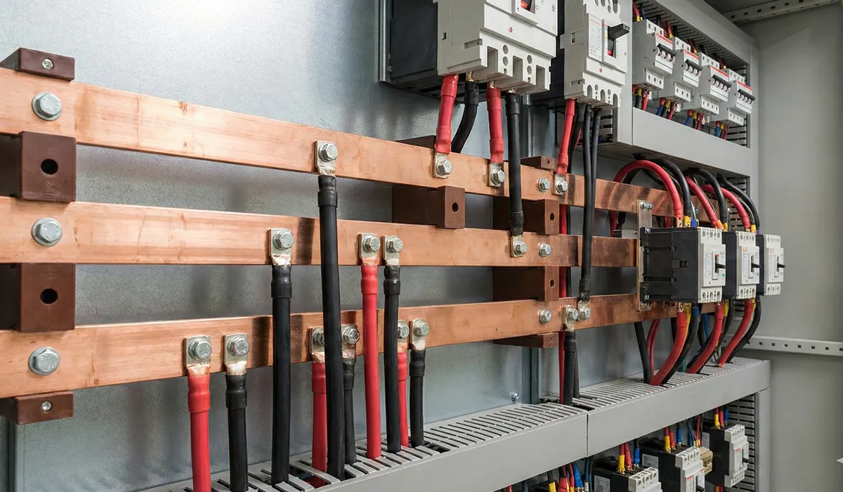
Busbars — fabricated from copper or aluminum conductors — distribute power internally within the assembly. Copper offers superior conductivity and is preferred for higher current ratings; aluminum provides a lighter, lower-cost alternative acceptable at moderate current densities. Control and secondary wiring implement interlocking schemes, auxiliary contact supervision, and alarm annunciation.
For a comprehensive understanding of busbar harmony, we highly recommend reviewing this article.
Safety Standards and Compliance: Why Switchgear Purpose Dictates Design Requirements
Why is switchgear important in high-voltage electrical systems? Because its fundamental purpose — protecting people, equipment, and continuity of supply — drives every design requirement, from dielectric withstand voltage to arc-resistant enclosure classification. Standards do not constrain switchgear design arbitrarily; they codify the minimum performance necessary for the equipment to fulfil its protective mandate reliably across its service life.
Further exploration of steel panels can be found in the following recommended reading.
IEC 62271 Parts 1, 100, 200, and 201 constitute the global benchmark for HV switchgear. Part 100 governs AC circuit breakers; Part 200 covers metal-enclosed assemblies for voltages above 1 kV. The ANSI/IEEE C37 series serves North American markets with equivalent scope, defining interrupting ratings, test protocols, and metal-enclosed bus requirements aligned to UL and NEMA practices.
In the United States, NFPA 70 (NEC) Articles 230 (Services), 408 (Switchboards and Panelboards), and 490 (Equipment over 1,000 V) govern switchgear installation. UL 1558 and UL 891 provide the UL listing framework for metal-enclosed switchgear and switchboards respectively, confirming compliance for AHJ approval.
European installations must satisfy EN 61439 for LV switchgear and controlgear assemblies, and EN 50123 for DC switchgear used in railway traction applications. IEC vs UL certification requirements diverge primarily on test methodology and rated service conditions, requiring careful review when equipment crosses between markets.
For a comprehensive understanding of Sivacon panel, we highly recommend reviewing this article.
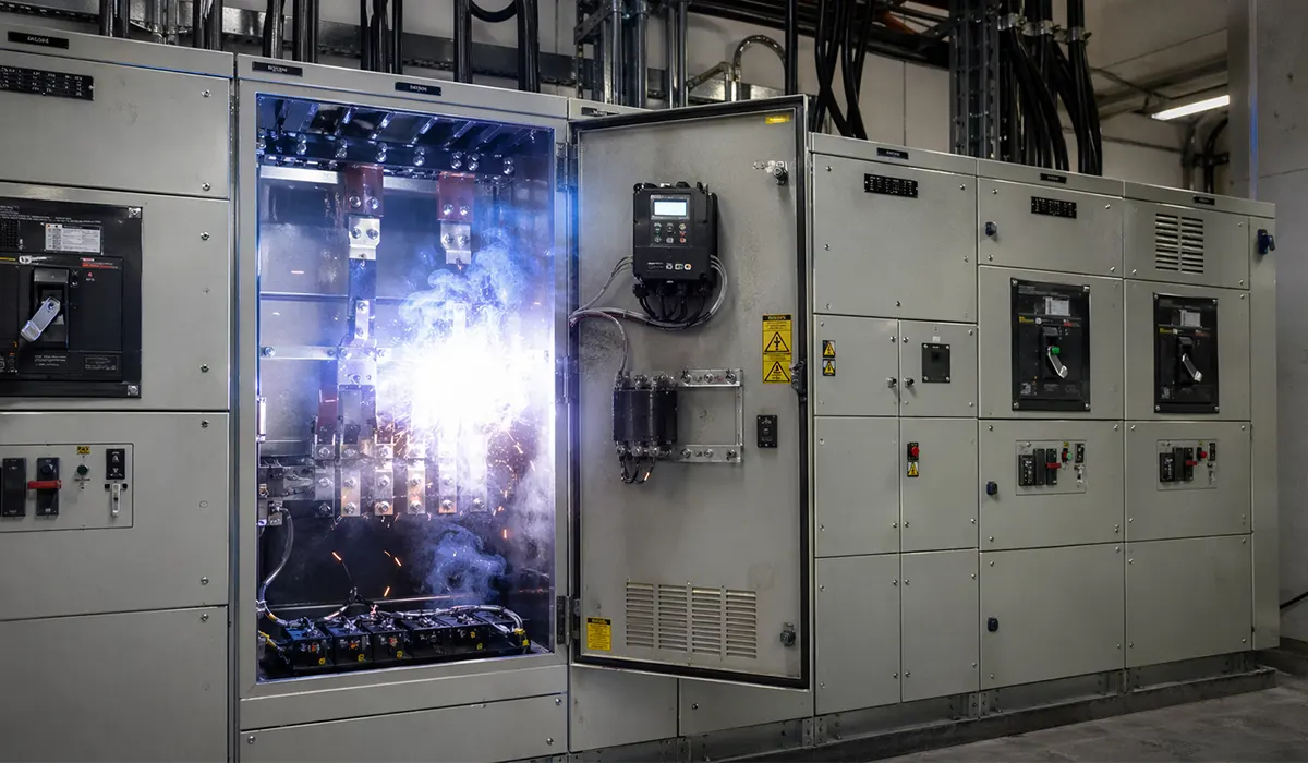
Arc Flash Hazard and the Switchgear Engineer’s Duty of Care
Arc flash — an uncontrolled electrical discharge through ionized air — is a direct consequence of switchgear failure or incorrect operation, releasing incident energy quantified in cal/cm². IEEE 1584-2018 provides the calculation methodology: incident energy decreases as switchgear fault clearing time shortens, making relay coordination and breaker response time critical arc flash mitigation variables. Arc-resistant switchgear per IEEE C37.20.7 redirects arc energy through controlled pressure-relief venting, protecting nearby personnel from blast overpressure and thermal burns.
Modern numerical IEDs incorporate maintenance mode settings that temporarily tighten overcurrent relay pickup thresholds during live-work periods, reducing arc flash incident energy without requiring physical hardware changes. This feature directly supports the engineer’s duty of care obligation under NFPA 70E 2021 to select appropriate arc-rated PPE based on calculated incident energy levels.
Further exploration of arc breakers can be found in the following recommended reading.
Future Trends: Smart Switchgear and Digital Substation Technology
How does electrical switchgear work in the digital substation era? IEC 61850-based process bus architecture replaces conventional copper secondary wiring with fiber-optic Ethernet links between primary equipment and protection IEDs, reducing installation labor, eliminating analogue signal degradation, and enabling full digital event recording from the point of measurement. Performance-focused modernization is also covered in switchgear performance.
Condition-based monitoring — integrating partial discharge detection, SF₆ gas density tracking, thermal imaging sensors, and vibration analysis — allows maintenance teams to identify developing faults well before failure, shifting from time-based schedules to predictive maintenance strategies validated by AI-driven analytics platforms.
The EU F-Gas Regulation 2024/573 mandates a phased prohibition on SF₆ in new switchgear equipment across European markets. Alternative insulation media are now commercially available: g³ gas (a Novec-based fluoronitrile mixture from 3M and GE) and clean dry air are deployed in certified MV and HV GIS installations. The indoor vs outdoor application context, temperature range, and pressure envelope each influence which alternative medium is specified.
Modular, factory-assembled switchgear solutions are accelerating deployment in utility-scale solar and wind projects, where rapid installation timelines, remote logistics, and reduced on-site skilled labor availability make pre-tested, plug-and-play power control equipment the preferred procurement model for project developers and EPCs alike.
Conclusion: The Indispensable Role of Switchgear in Modern Electrical Infrastructure
The basic purpose of electrical switchgear — protecting electrical circuits, controlling power flow, and safely isolating equipment — remains constant from a 400 V LV panel in a commercial building to a 400 kV GIS installation in a transmission substation. Only the scale, the insulation medium, and the communication architecture change.
Across every voltage tier, the frameworks established by IEC 62271, ANSI/IEEE C37, and NFPA 70 ensure that switchgear fulfils its protective mandate verifiably and consistently throughout its service life. These standards are not administrative hurdles; they are the engineering codification of switchgear’s core purpose.
For engineering teams specifying new installations or planning upgrades, understanding what is the basic purpose of electrical switchgear from first principles is the essential foundation. Download our Switchgear Standards Reference Card for a consolidated IEC/ANSI/NFPA/UL standards guide by voltage class, or consult with a certified electrical engineer to ensure your switchgear specification meets both the operational demands and the applicable regulatory framework for your project.
FAQ
What is the basic purpose of electrical switchgear in a power system?
Electrical switchgear serves three core purposes: protecting circuits and equipment from fault conditions using protective relays and circuit breakers; controlling the switching of power circuits for operational and maintenance needs; and providing safe, visible isolation of electrical apparatus to protect personnel during maintenance.
What is the role of electrical switchgear in power distribution systems?
In power distribution, switchgear forms the switching and protection layer at every voltage boundary — from the incoming utility supply through transmission substations to distribution feeders and end-user facilities. It controls power flow via busbar configurations, protects transformers and cables from faults, and integrates with SCADA systems using IEC 61850 protocols for real-time monitoring and remote operation.
What is the difference between electrical switchgear and circuit breakers in substations?
A circuit breaker is a single current-interrupting device rated to open under fault conditions. Electrical switchgear is the complete assembly — comprising circuit breakers, disconnect switches, instrument transformers, busbars, protective relays, and control wiring — that collectively performs protection, switching, isolation, and metering within an enclosed, standardized structure. The breaker is one component; switchgear is the integrated system.
Why is switchgear important in high-voltage electrical systems?
At high voltages, the consequences of uncontrolled fault current — equipment destruction, arc flash injury, and supply interruption — are severe. HV switchgear limits these consequences by interrupting fault current within milliseconds, isolating the faulted section while keeping healthy circuits energized, and providing the controlled insulation environment necessary to operate safely at voltages from 36 kV up to 1,100 kV in GIS installations.
How does electrical switchgear protect industrial circuits from faults?
Industrial switchgear integrates numerical IEDs programmed with overcurrent (ANSI 50/51), differential (ANSI 87), and earth fault protection functions. On detecting an abnormal condition, the IED issues a trip command to the circuit breaker within milliseconds. Zone-selective interlocking (ZSI) ensures only the nearest upstream breaker operates, minimizing arc flash energy and preserving supply to unaffected production areas.
What is the purpose of medium voltage switchgear in industrial power networks?
Medium voltage switchgear (1 kV–36 kV) provides feeder-level protection and control between the utility supply transformer and the LV motor control centers or distribution boards that serve individual loads. It controls large feeder cables and motors at ratings where LV switchgear is no longer appropriate, while maintaining selective coordination to limit fault propagation across the industrial network.