


One reason buyers, engineers, and even experienced maintenance teams get confused is that the words panel, switchboard, panelboard, and switchgear are often used loosely in conversation. In practice, an electrical panel is usually the enclosed assembly that receives power and redistributes it to downstream circuits, while switchgear is the broader category of switching, protection, control, and isolation equipment used across low-, medium-, and high-voltage systems. The distinction matters because the design rules, safety expectations, test standards, and operating environments are not the same.
This guide explains the foundations engineers and facility managers actually need: panel types and functions, low voltage switchgear and medium voltage switchgear concepts, component selection, enclosure ratings, IEC and ANSI/IEEE frameworks, arc-flash safety, digitalization, commissioning, maintenance, and practical specification logic. The goal is not marketing language. It is to help readers make better design, procurement, and lifecycle decisions with clearer technical boundaries.
Modern projects also demand a more integrated view than in the past. A distribution board is no longer just a steel box with breakers, and a switchgear lineup is no longer purely electromechanical. Today’s assemblies increasingly combine protection, metering, communication, condition monitoring, and remote diagnostics, which means mechanical layout, thermal behavior, standards compliance, cybersecurity, and maintainability all influence equipment value over its full service life.
Alternatively, an audio version of this article is available below for your convenience
Electrical Panel & Switchgear Basics: Definitions, Types, and Core Functions
Switchgear basics start with one principle: an electrical panel is the enclosure most people see daily, but the switchgear category sits above it in the power-system hierarchy. The panel accepts incoming power from a transformer, generator, UPS, or utility source and redistributes it to branch or feeder circuits feeding lighting, receptacles, motors, HVAC equipment, and process loads. Depending on the region, engineers call it a distribution board, panelboard, breaker panel, load center, or switchboard — but the function is identical: distribute power safely, selectively, and with ratings matched to the installation.
Three panel families cover most installations:
- Main Distribution Board (MDB) — sits closest to the source, handles the highest downstream distribution duty, and usually drives the design envelope for the entire LV network.
- Sub-Distribution Boards (SDBs) — divide power by area, floor, production zone, or tenant.
- Load centers / consumer units — lighter-duty assemblies common in residential and light commercial installations.
In industrial work, specialized assemblies such as MCCs, power factor correction panels, and automation control panels extend the same enclosure-based logic into motor control and process applications.
Suitability is never just about enclosure size. Engineers must match ampacity, rated voltage, short-circuit withstand capability, busbar design, breaker interrupting capacity, and ingress protection to the available fault current and operating environment. A panel that is fine for a dry indoor commercial installation can be completely wrong for a humid process plant, a washdown zone, an outdoor utility yard, or a high-fault industrial feeder. That mismatch is where most field failures begin.
Main Distribution Board (MDB) — Role and Design Characteristics
The MDB is the first major point of low-voltage distribution downstream of the transformer or service entrance. In real projects, it is the assembly that establishes the main bus, main incomer protection, outgoing feeder arrangement, metering point, and the grounding and earthing reference for the distribution network. Because it sits at the top of the LV hierarchy, its current rating, busbar arrangement, and short-circuit performance usually drive much of the downstream design envelope.
A typical MDB includes an incoming section, a busbar chamber, feeder breaker compartments, metering instruments, CTs for protection or energy measurement, neutral and protective earth bars, and cable or busduct termination space. Typical ratings vary widely by project, but the assembly is commonly designed around higher current levels and fault duties than an SDB. In industrial and infrastructure work, bus coupling and future extension are also important because the MDB often becomes the long-term expansion backbone for the plant. If the information related to MDB design was interesting and informative to you, researching cubic switchboard design can be very engaging.
Sub-Distribution Boards and Load Centers
SDBs sit downstream from the MDB and serve localized loads. Their job is to shorten feeder runs, improve selectivity, simplify maintenance isolation, and organize distribution by process area, floor, or occupancy zone. In a manufacturing plant, one SDB may serve packaging lines while another supplies utilities, HVAC, or clean-room loads. In commercial buildings, they often segment lighting, receptacles, and mechanical systems by level or tenant.
Further exploration of Electrical Panels can be found in the following recommended reading.
Load centers are the lighter end of this category. They are common in residential and light commercial installations, where the assembly houses branch protective devices and distributes power to final circuits. Across both SDBs and load centers, balanced three-phase loading matters. Poor phase balance increases neutral current stress, heating, voltage imbalance, and nuisance operational issues, especially when nonlinear loads and harmonics are present. For a comprehensive understanding of harmonic filtering, we highly recommend reviewing this article.
Motor Control Centers (MCC) — Specialized Panel Applications
A useful long-tail question here is how does a motor control center differ from a switchgear panel. An MCC is a specialized panel assembly intended for motor feeders and motor-related controls. Instead of only housing feeder breakers, it typically includes motor starters, variable frequency drives, overload relays, control wiring, operator interfaces, and sometimes communication modules for diagnostics and automation integration. That makes it closer to a production asset interface than a general-purpose electrical distribution panel.
MCCs are standard in water treatment, process plants, mining, HVAC central plants, and heavy manufacturing. Engineers often choose between fixed-mounted and draw-out unit designs. Fixed units reduce cost and mechanical complexity, while draw-out units improve maintainability, testing access, and replacement speed. That tradeoff is a classic example of capex versus lifecycle serviceability. If the details you gathered about MCC selection were interesting and insightful, you may find diving deeper into industrial control systems equally captivating.
Electrical Switchgear vs Panel: Core Definitions and Key Differences
The most-searched question in this topic — and the one that drives the most specification errors — is the switchgear vs panel distinction. Here’s the cleanest framing engineers can rely on:
Electrical switchgear is the broader functional category. It covers assemblies and devices used to switch, protect, control, and isolate circuits across LV, MV, and HV systems. An electrical panel is one type of enclosed distribution assembly within that broader category. In other words: every panel performs distribution; not every switchgear assembly is just a panel.
The contrast sharpens as voltage, fault current, and operational duty climb. Primary switchgear must interrupt heavy faults, maintain insulation coordination, contain internal arc stresses, and support relay-based selectivity under conditions a typical final distribution board never sees. That is why switchgear standards, compartmentation practices, breaker technologies (vacuum, gas, air), and test philosophies differ fundamentally from those used in common panelboards.
A useful mental model:
| Aspect | Electrical Panel | Electrical Switchgear |
|---|---|---|
| Primary job | Distribute loads to downstream circuits | Manage power-system events (fault, isolation, switching) |
| Typical voltage | LV (≤1,000 V) | LV, MV, HV (up to 800+ kV) |
| Protection logic | Mostly local overcurrent | Coordinated relay-based selectivity |
| Maintenance philosophy | Periodic inspection | Withdrawable, interlocked, condition-monitored |
| Governing standards | IEC 61439 / UL 67 / UL 891 | IEC 62271 / IEEE C37 |
| Failure consequences | Local outage | Bus loss, arc-flash event, cascading trip |
The overlap is real in low-voltage installations — there, the difference is mostly degree, not kind. But the moment a project crosses into MV or HV territory, the panel/switchgear distinction stops being semantic and starts driving structural design decisions.
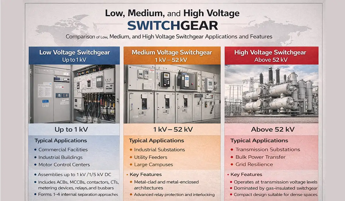
Low Voltage Switchgear (Up to 1 kV)
Low voltage switchgear generally covers assemblies up to 1,000 V AC or 1,500 V DC under the IEC framework. These lineups house ACBs, MCCBs, contactors, CTs, metering devices, relays, and busbars in metal-enclosed structures designed for feeder, incomer, tie, and motor applications. In commercial and industrial facilities, this is where panelboard logic starts to overlap with true power switching apparatus.
One important construction topic is Form of Separation. Under IEC/EN practice, internal separation defines how busbars, functional units, and terminals are segregated from one another, ranging from lower separation approaches to higher compartmentalization such as Form 4. Higher forms improve safety, maintainability, and fault containment boundaries, but they also affect footprint, cost, and cable termination complexity. Further exploration of low vs high voltage can be found in the following recommended reading.
Medium Voltage Switchgear (1 kV – 52 kV)
For many buyers, the real breakpoint is a low voltage vs medium voltage switchgear comparison. Medium voltage switchgear serves industrial substations, utility feeders, large campuses, and critical infrastructure where the consequences of faults, outages, or unsafe maintenance are much higher. It commonly includes relay protection, vacuum interruption, instrument transformers, interlocking, and more formal compartmentalization than typical LV equipment.
A common follow-up is what is metal-clad switchgear used for. Under IEEE practice, metal-clad switchgear refers to compartmentalized MV assemblies with grounded metal barriers and draw-out circuit breakers. By contrast, metal-enclosed switchgear is broader and may include interrupter switches, breakers, fuses, metering, and protective devices in configurations that are not strictly metal-clad. The difference matters for maintenance access, isolation philosophy, and application duty.
In technology terms, vacuum circuit breakers dominate modern MV interruption, while gas-insulated solutions remain important where compact footprint, environmental sealing, or site constraints drive the decision. Air-insulated and gas-insulated architectures each have advantages, which is why engineers still evaluate air-insulated vs gas-insulated, indoor vs outdoor, and fixed vs withdrawable arrangements during specification. If the information on medium voltage switchgear was engaging, gathering more knowledge about industrial switchboards could be very exciting.
High Voltage Switchgear (Above 52 kV)
High-voltage and extra-high-voltage switchgear operate at transmission-level duties where insulation coordination, footprint efficiency, switching reliability, and environmental performance dominate the design conversation. At this level, the equipment is less about local distribution and more about bulk power transfer, substation topology, and grid resilience.
GIS, or gas-insulated switchgear, has become the dominant compact solution for many HV applications because it can deliver high reliability in a much smaller footprint than conventional air-insulated yards. That is especially important in dense urban substations, offshore platforms, and sites with severe space constraints. Increasingly, utilities and OEMs are also evaluating low-emission and SF6-free approaches as environmental requirements tighten. If the content related to high voltage switchgear was both interesting and helpful, further study of switchgear fault protection could be just as fascinating.
Medium and Low Voltage Electrical Panels: When to Use Each
Most facility decisions don’t sit cleanly in the LV-only or MV-only camp — they straddle both. Understanding when medium and low voltage electrical panels each make sense is one of the most practical specification skills an engineer can develop.
Low voltage electrical panels (≤1,000 V AC under IEC; ≤600 V AC under traditional ANSI): the workhorse for final distribution. They serve lighting, receptacles, HVAC loads, motors under roughly 200 kW, and most process equipment. Built to IEC 61439 (or UL 67/891 in North America), LV panels are cheaper per amp, easier to maintain by general electricians, and typically housed in IP3X–IP5X enclosures.
Medium voltage electrical panels (1 kV – 52 kV): used wherever the available current at LV would force impractically large conductors and breakers. The rule of thumb most engineers use: if continuous load exceeds 2–3 MW at a single bus, MV distribution usually wins on cable cost, voltage drop, and short-circuit current management. MV panels are built to IEC 62271 / IEEE C37, require trained MV technicians, and use vacuum or SF6/SF6-free interruption.
The selection logic in practice:
| Decision Factor | Low Voltage Electrical Panel | Medium Voltage Electrical Panel |
|---|---|---|
| Typical load | <2 MW total | >2–3 MW total |
| Cable size economics | Acceptable to ~1,500 A | Becomes prohibitive above ~2,000 A |
| Fault current | Manageable up to ~100 kA | Required when LV fault levels become unmanageable |
| Voltage drop on long runs | Significant beyond 100–150 m | Negligible — favors campus and process plants |
| Operator skill requirement | General qualified electrician | MV-certified technician |
| Capex | Lower per unit | Higher per unit, often lower per kW delivered |
Industrial facilities often use both: an MV switchgear lineup steps utility power down at the main substation, feeds one or more transformers, and LV panels distribute from there to motor control centers, lighting subs, and process loads. Specifying the right boundary between medium and low voltage electrical panels — typically the transformer location — is one of the highest-leverage decisions in plant electrical design.
Key Components of a Switchgear Panel: Breakers, Busbars, Relays & CTs
A switchgear panel is not a steel cabinet with breakers thrown inside. It’s a coordinated system in which conductors, protective devices, sensing elements, metering, insulation structures, mechanical barriers, and HMIs all work to a single set of rated values. Getting one element wrong compromises selectivity, heat rise, maintenance access, fault performance, or future expansion — and it usually doesn’t show up until first energization or first fault.
The table below summarizes the main components found inside any switchgear panel — from a 200 A residential load center to a 6,300 A LV switchboard or an 11 kV MV cubicle. The exact mix changes; the function categories don’t.
| Typical Standards | Key Specification Parameters | Function | Component |
|---|---|---|---|
| IEC 60947-2 | Rated current, Icu/Ics or short-time withstand, trip unit type | Main incomer/feeder overcurrent and short-circuit protection | Air Circuit Breaker (ACB) |
| IEC 60947-2 | Frame size, interrupting capacity, trip settings | Branch feeder and motor protection | Molded Case Circuit Breaker (MCCB) |
| IEC 60898-1 | Trip curve (B/C/D), rated current, breaking capacity | Final circuit protection | Miniature Circuit Breaker (MCB) |
| IEC 61439 | Current rating, copper or aluminum, temperature rise, withstand | Internal power distribution conductor | Busbar |
| IEC 60255 | Function type, pickup settings, logic, communication protocol | Detects abnormal conditions and commands tripping | Protective Relay |
| IEC 61869-2 | Ratio, accuracy class, burden, thermal rating | Scales current for metering and protection | Current Transformer (CT) |
| IEC 61643-11 | Up, In, Imax, system compatibility | Limits transient overvoltages | Surge Protection Device (SPD) |
| IEC 61008-1 | Sensitivity, device type, response time | Detects ground fault current and disconnects circuit | Earth Leakage / RCD |
Three principles tie component selection together:
- Selectivity over budget. The breaker frame must match the bus rating and the fault study. Picking a cheaper breaker that fails the Icu requirement creates downstream selectivity gaps that show up as nuisance trips for years.
- CT class is not a catalog detail. Choose 5P10 or 10P10 for protection CTs, Class 0.5 or 0.2S for revenue metering, and verify burden against the connected relays and meters. Mismatch here distorts every measurement upstream.
- Thermal coordination is an assembly property, not a component property. The enclosure must dissipate the heat produced by all devices running simultaneously at rated load. IEC 61439 verification exists for exactly this reason — and it’s why switch gear panel design always begins with system data, not catalog browsing.
Busbars — Design, Material Selection, and Sizing
Busbars are the current-carrying backbone of both industrial electrical panels and switchgear. They collect and distribute power internally, connect incomers to feeders, and establish the thermal and short-circuit performance envelope of the entire assembly. Good busbar system design is not only about ampacity; it is also about joint integrity, spacing, support strength, creepage, clearance, and heat rise under real operating conditions.
The classic material choice is copper vs aluminum. Copper offers higher conductivity, more compact section sizes, and strong jointing performance, while aluminum reduces weight and material cost but needs more careful treatment of contact surfaces, joint design, and cross-sectional sizing. Neither option is automatically better; the right answer depends on current level, footprint, lifecycle economics, corrosion environment, and installation practice.
Sizing typically considers allowable current density, ambient conditions, enclosure heat dissipation, temperature rise limits, and short-circuit mechanical forces. Under IEC 61439, temperature-rise verification is a formal part of assembly compliance, which is why bus selection must be treated as part of the assembly verification process rather than a standalone conductor calculation.
Panel builders who fabricate busbars in-house rely on professional busbar processing and bending systems to meet the dimensional tolerances that IEC 61439 verification demands.
Circuit Breakers in Switchgear — Types and Selection Criteria
ACBs, MCCBs, and MCBs serve different roles. ACBs are usually selected for main incomers, bus couplers, and high-current feeders in switchgear or large switchboards. MCCBs are versatile feeder and motor-protection devices for industrial and commercial systems. MCBs are compact final-circuit devices more common in residential and light commercial distribution. Matching the device to the duty is part of sound switchgear fundamentals, not a purely budget decision.
One of the most misunderstood breaker concepts is the difference between Icu and Ics. Icu is the ultimate short-circuit breaking capacity, while Ics is the service short-circuit breaking capacity associated with continued service after a defined test sequence. In procurement reviews, Icu gets attention because it is the bigger number, but Ics is often more relevant to real operating resilience. For heavy-duty industrial use, electronic trip units also offer important advantages over thermal-magnetic designs by enabling better adjustment, coordination, monitoring, and event data. If the information about circuit breakers was valuable, researching GE breakers could be just as captivating.
Protective Relays and Metering in Modern Switchgear
Protective relays are the decision-making layer of modern switchgear. They evaluate current, voltage, frequency, and logic conditions to detect abnormal events such as overcurrent, earth fault, differential fault, undervoltage, and feeder anomalies, then issue trip commands to the appropriate breaker. In medium-voltage and high-voltage systems, relay philosophy is often the real heart of system selectivity.
The technology shift from electromechanical relays to numerical relays has transformed switchgear capability. Modern IEDs combine protection, metering, disturbance recording, logic, event logging, and communications in a single platform. With the right architecture, they feed SCADA, DCS, BEMS, or digital substation environments while supporting interoperability through standardized protocols.
CTs and VTs support this layer by scaling primary electrical quantities into values suitable for metering and protection circuits. Their accuracy class, burden, and ratio selection are not clerical details. Poor CT choice can distort metering, compromise relay performance, or mislead energy analysis. If the material related to protective relays was both useful and intriguing, diving into switchgear performance optimization will likely be equally fascinating.
Electrical Panel and Switchgear Enclosures — IP and NEMA Ratings Explained
Enclosure choice is not cosmetic. It determines whether the assembly survives dust, hose-down cleaning, wind-driven rain, corrosion, accidental contact, and heat buildup. In global projects, engineers typically work with two parallel systems: IP ratings under IEC 60529 and NEMA types under NEMA 250. They are related but not identical, so engineers should avoid treating them as one-to-one equivalents.
As a rule, IP describes resistance to solids and liquids through a two-digit code, while NEMA addresses a wider environmental application picture that can include corrosion, oil, and construction expectations. That is why “IP65 equals NEMA 4” may be a useful rule of thumb, but not a complete engineering decision. If you enjoyed learning about enclosure ratings, investigating Rittal electrical panels might also offer a similarly engaging experience.
| Typical Application | Approx. NEMA Equivalent | IP Rating (IEC) | Protection Level |
|---|---|---|---|
| Office / commercial indoor | NEMA 1 | IP31 | Standard indoor |
| Indoor industrial | NEMA 12 | IP54 | Dust-tight, splash-proof |
| Outdoor / washdown | NEMA 4 | IP65 | Dust-tight, hose-proof |
| Flood-prone areas | NEMA 6P | IP68 | Waterproof (submersible) |
| Hazardous process zones | NEMA 7/9 | Ex / ATEX context | Explosion-proof / hazardous |
These pairings are application-oriented approximations, not literal equivalence mappings, and should always be checked against project requirements and local code expectations.
Thermal Management and Ventilation in Electrical Enclosures
As component density rises, electrical panel ventilation and thermal management become more important. Heat from breakers, drives, power supplies, relays, and communication devices accumulates quickly in enclosed spaces. Left unmanaged, that heat reduces component life, shifts protective behavior, and increases nuisance failures.
Engineers typically choose between passive and active strategies. Passive methods include louvers, chimney effect, and natural convection. Active solutions include filter fans, air conditioners, air-to-air heat exchangers, and closed-loop cooling units. The correct choice depends on load density, ambient temperature, contamination level, and whether the enclosure must stay sealed. In other words, natural ventilation vs forced cooling is not just a cost question; it is a reliability question. If the content on thermal management was interesting and insightful, continuing to explore steel electric panels could be both exciting and beneficial.
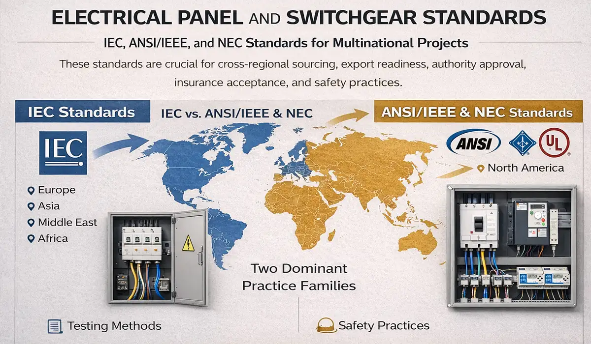
Electrical Panel and Switchgear Standards — IEC, ANSI/IEEE, and NEC
For multinational projects, Electrical Panels and Switchgear Basics is never complete without a standards map. Standards are not paperwork added after design; they are the framework that determines test philosophy, assembly verification, insulation rules, labeling, enclosure expectations, and safety practices. Compliance also affects insurance acceptance, authority approval, export readiness, and vendor comparability.
At a broad level, the world divides into two dominant practice families. IEC standards dominate much of Europe, Asia, the Middle East, and Africa. ANSI/IEEE, UL, and the NEC remain central in North America. Global EPC firms, OEMs, and facility owners often need fluency in both, especially when sourcing equipment cross-regionally or building plants for multinational operators. This article serves as a valuable resource for those seeking detailed information on switchboard testing methods.
Key IEC Standards for Panels and Switchgear
For low-voltage assemblies, IEC 61439 defines the general and product-specific requirements for switchgear and controlgear assemblies. IEC 60947 governs low-voltage switchgear and controlgear devices such as breakers and disconnectors. IEC 60529 defines degrees of protection provided by enclosures through the IP code. For higher-voltage applications, the IEC 62271 family provides the main framework for high-voltage switchgear and controlgear. Together, these standards establish the language of ratings, verification, service conditions, and enclosure performance in IEC markets. If the insights you gained from IEC standards were intriguing, exploring Sivacon panel standards might be of great interest as well.
ANSI/IEEE and NEC Standards for the North American Market
North American practice layers several documents together. The IEEE C37 family covers many switchgear, breaker, and protective relay topics. The NEC, especially Article 408, addresses switchboards, switchgear, and panelboards in installation practice. UL 891 is a major product standard for dead-front switchboards, while NFPA 70E governs electrical safety in the workplace, including shock and arc-flash risk control. Engineers also rely on related NEC articles such as Article 430 for motor circuits and MCC-related design contexts. If the information about ANSI/IEEE standards was valuable, researching 200 amp panels could be just as captivating.
IEC vs ANSI/IEEE — Key Differences Every Engineer Should Know
The biggest practical contrast is performance-based vs design-based emphasis. IEC standards generally focus on what the assembly must achieve under defined conditions, while ANSI/IEEE and related North American practices often prescribe more detailed product-format expectations. That difference influences footprint, compartment architecture, rating conventions, testing language, and documentation style. For a comprehensive understanding of modern switchgear evolution, we highly recommend reviewing this article.
| ANSI/IEEE Framework | IEC Framework | Parameter |
|---|---|---|
| North America | Europe, Asia, Middle East, Africa | Primary market |
| UL 891 / UL 508A / related North American practice | IEC 61439 | LV assembly baseline |
| IEEE C37 family | IEC 62271 family | MV switchgear baseline |
| NFPA 70E / IEEE 1584 | IEC equipment standards + local practice | Arc-flash workplace safety |
| Commonly up to 600 V AC in legacy North American practice | Up to 1,000 V AC | Traditional LV voltage reference |
| Product/type-based testing and listing traditions | Design verification and routine verification | Design philosophy |
The table highlights broad engineering tendencies, not a complete substitution matrix, and project-specific documents always take precedence.
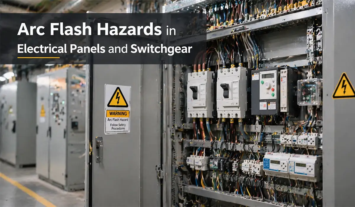
Arc Flash Hazards in Electrical Panels and Switchgear — Safety Essentials
When engineers ask how does arc flash protection work in switchgear, the first step is understanding the hazard itself. An arc flash is the rapid release of heat, light, pressure, and molten material caused by an electrical arc fault. It is one of the most severe maintenance hazards associated with energized equipment. NFPA 70E centers workplace safety around recognition of these hazards, and ESFI’s published occupational data continue to show real electrical injuries and documented arc-flash fatalities in workplace statistics. If you are looking for more information about arc fault breakers, it is recommended not to miss reading this article.
Severity depends on more than nominal voltage. Available fault current, conductor geometry, working distance, protective device clearing time, compartment construction, and maintenance condition all influence exposure. That is why an apparently routine switching or inspection task can carry very different risk levels from one assembly to another. Proper design and maintenance directly affect outcome.
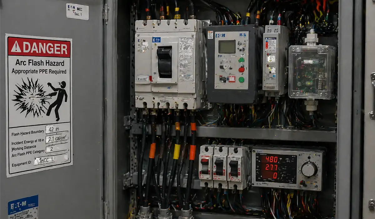
Arc Flash Risk Assessment and Incident Energy Calculation
IEEE 1584 provides the calculation framework used to estimate incident energy and arc-flash boundary in many industrial studies. The model considers variables such as available fault current, working distance, equipment type, and clearing time of the upstream protective device. In practice, reducing clearing time is one of the most powerful ways to reduce exposure because arc energy escalates with duration.
Once the study is complete, facilities apply labels, work practices, and PPE decisions under the applicable safety framework. In North America, NFPA 70E ties that calculation work to field risk controls, energized work practices, and labeling expectations. Further exploration of emergency electrical panels can be found in the following recommended reading.
Arc Flash Mitigation Strategies in Switchgear Design
Mitigation starts with design choices. Zone-selective interlocking (ZSI) reduces tripping delay during severe downstream faults while preserving coordination in normal selectivity conditions. Arc-detection relays use light and pressure cues to trip rapidly. Current-limiting devices reduce let-through energy. Remote racking and remote operation increase worker distance. Arc-resistant constructions redirect pressure away from personnel. These are not optional premium features in high-risk installations; they are tools for reducing incident energy and maintenance exposure. If the information on arc flash mitigation was engaging and informative, gathering more knowledge about circuit breaker selection could be very exciting.
Smart Switchgear and the Digital Transformation of Power Distribution
Switchgear is no longer just a passive electromechanical barrier between power source and load. In modern facilities, it is becoming a data-rich node in Industry 4.0 and smart-grid architecture. Embedded sensors, digital trip units, networked meters, and gateway devices now support real-time visibility into equipment status, energy behavior, breaker health, and protection events. That shift is changing both maintenance strategy and procurement expectations. If the content related to digital transformation was both interesting and helpful, further study of electrical panel design could be just as fascinating.
The contrast between manual vs digital operation is increasingly economic as much as technical. Conventional assemblies rely heavily on periodic manual inspection. Smart switchgear supports event-driven maintenance, trending, remote diagnostics, and faster root-cause analysis. As uptime expectations rise, that difference matters.
IEC 61850 Communication Protocol in Modern Switchgear
IEC 61850 is the major international framework for communication networks and systems in power utility automation and digital substations. It enables interoperability between IEDs, protection devices, and system-level applications by standardizing data models and communication methods rather than forcing one proprietary ecosystem. For modern switchgear, that means easier integration with station bus, process bus, and higher-level control systems.
Two frequently discussed concepts are GOOSE messaging and sampled values. GOOSE supports fast event messaging such as trip and status exchange, while sampled values support digital measurement streams for protection and control architectures. Together, they enable more flexible and interoperable designs than isolated hardwired-only schemes. If the insights you gained from IEC 61850 were intriguing, exploring busbar electrical harmony might be of great interest as well.
Predictive Maintenance and Condition Monitoring in Switchgear
Condition monitoring turns switchgear from a maintenance interval problem into a data problem. Thermal sensors, operation counters, contact wear analytics, gas-pressure monitoring, partial-discharge data, and breaker-health indicators help teams identify deterioration before it becomes an outage. That supports predictive maintenance rather than strictly time-based intervention.
The operational benefit is reduced unplanned downtime and better maintenance targeting. Instead of opening every cubicle on a rigid schedule, teams can prioritize the units showing real signs of heat rise, abnormal operation count, insulation distress, or environmental exposure. This is the practical side of the digital twin idea in switchgear lifecycle management. Since condition monitoring plays a crucial role in reliability, obtaining more information about busbar switchboard systems can be very important and essential.
Smart Panelboards and Energy Management Systems
Smart panelboards extend digitalization into branch-level distribution. With connected breakers, panel servers, and power meters, they can provide circuit-level energy data, alarm visibility, and remote monitoring from edge or cloud platforms. That makes them useful not only for protection, but also for energy management, tenant billing, load optimization, and operational troubleshooting.
For measurement quality, IEC 61557-12 defines requirements for power metering and monitoring devices used within electrical distribution systems. In practice, that helps teams distinguish between simple current indication and more robust power-quality or monitoring capability suitable for BEMS, SCADA, or plant analytics workflows. If you are looking for more information about capacitor switchboards, it is recommended not to miss reading this article.
Switchgear Panel Board Construction: Assembly Types, Forms of Separation & Wiring
A switchgear panel board sits at the intersection of two product families — the panelboard (final-circuit distribution) and the switchgear lineup (primary switching and protection). In practice, it’s the term most often used for low-voltage assemblies that handle both incoming feeder protection and outgoing branch distribution from a single enclosure.
Switchgear panel board construction is governed primarily by IEC 61439-1/-2 in international markets and UL 891 (dead-front switchboards) or UL 67 (panelboards) in North America. The standards specify how the assembly must perform — they don’t dictate every dimension, which is why two panels with the same nameplate ratings can have very different internal architectures.
Three construction characteristics define a switchgear panel board:
1. Assembly type.
- Type-tested assemblies (TTA) — fully verified by the original manufacturer through type tests.
- Partially type-tested assemblies (PTTA) — common in custom panel-builder work; some components verified by test, others by calculation under IEC 61439 design verification rules.
2. Form of Separation (IEC 61439). Defines internal barriers between busbars, functional units, and terminals:
- Form 1 — no internal separation (rarely used today).
- Form 2 — busbars separated from functional units.
- Form 3 — busbars separated from functional units, functional units separated from each other.
- Form 4 — full separation including terminals; highest safety, maintainability, and cost.
Process plants and critical facilities typically specify Form 3b or Form 4 to allow live maintenance on one feeder while adjacent ones remain energized.
3. Wiring discipline. Power wiring separated from control wiring, control wiring routed in trunking with 30% spare capacity, all terminals labeled to schematic numbers, torque marks on every busbar joint. Sloppy wiring is the leading cause of nuisance trips during the first 12 months of service — not poor protection coordination.
A switchgear panel board built and verified properly under IEC 61439 will deliver 25–30 years of service. One built without that discipline rarely makes it past the first major fault.
Electrical Panel and Switchgear Repair Services Market: What Buyers Should Look For
The electrical panel and switchgear repair services market has grown into a multi-billion-dollar global segment, driven by an aging installed base, extended equipment lead times (often 40–80+ weeks for new MV switchgear), and the rising cost of unplanned downtime in process and infrastructure sectors. For facility owners, repair and refurbishment is no longer a fallback — it’s often the most economically rational lifecycle strategy.
Repair services typically cover four categories:
- Breaker refurbishment — overhaul of ACBs, MCCBs, vacuum and SF6 MV breakers, including contact replacement, mechanism rebuild, trip unit calibration, and full functional testing per IEC 62271-100 / IEEE C37.09.
- Bus and enclosure repair — re-bussing of damaged sections after fault events, replacement of corroded enclosures, reinstallation of insulation barriers.
- Retrofit and reverse-engineered replacement parts — for obsolete OEM gear where original spares are no longer manufactured (common with switchgear from the 1980s–1990s).
- Protection system upgrades — replacing electromechanical relays with numerical IEDs while reusing the existing primary equipment, often delivered as a digitalization project rather than a repair.
What to look for when selecting a repair partner:
| Selection Criterion | What “Good” Looks Like |
|---|---|
| Standards compliance | Repairs verified to IEC 62271, IEEE C37, or relevant UL standards with documented test reports |
| Trace ability | Every component changed logged with serial number, lot, and certificate of conformity |
| Test capability | In-house primary injection, secondary injection, high-pot, and partial-discharge testing — not subcontracted |
| Lead time | Realistic and committed in writing, with progress milestones for major refurbishments |
| Warranty | Minimum 12 months on the repaired equipment under defined operating conditions |
| Engineering support | Ability to read original drawings, perform coordination studies, and re-issue updated documentation |
The buyers most exposed to risk in this market are those who treat panel and switchgear repair as a commodity price comparison. The cheapest quote often skips testing rigor, uses non-OEM-equivalent parts, and leaves the asset legally and electrically uncertified — a small saving today that becomes a much larger problem when the equipment next operates under fault.
Decision rule: when total cost of repair exceeds 50–60% of comparable new-equipment cost and lead time advantage disappears, replacement starts to win. Below that threshold, qualified repair almost always delivers better lifecycle economics than new equipment.
Electrical Panel and Switchgear Installation, Commissioning, and Maintenance
Even a well-designed assembly can underperform if it is badly installed or poorly maintained. Mechanical alignment, cable routing, torque control, environmental protection, interlock testing, and protection-setting validation all affect how the equipment behaves under real service conditions. This is where design intent meets field reality.
Lifecycle quality is especially sensitive in switchgear because the equipment may sit idle for long periods and then be expected to operate flawlessly during a fault. That means installation quality, commissioning discipline, and maintenance strategy are not separate topics; they are three phases of one reliability process. Further exploration of underground electrical conduit can be found in the following recommended reading.
Installation Requirements and Site Conditions
Installation requirements go beyond “fit the lineup and land the cables.” Engineers must confirm clearances, access space, cable segregation, grounding and earthing continuity, support plinth accuracy, ventilation path, and ambient conditions. Site altitude and temperature may require derating. Humid environments may need anti-condensation heaters. Outdoor equipment may need sunshielding, drainage planning, or corrosion-resistant construction.
Local code compliance also matters. An IEC-compliant assembly still has to satisfy the installation jurisdiction, and a UL/ANSI assembly still has to be installed according to the NEC and project documents. This is why installation reviews should always include both manufacturer instructions and governing code requirements. If the information about installation requirements was valuable, researching industrial wiring could be just as captivating.
Switchgear Commissioning Checklist
Before energization, commissioning should confirm that the assembly matches the protection study, the mechanical build, and the installation drawings. A disciplined checklist is one of the simplest ways to prevent avoidable failures at first energization. If you enjoyed learning about commissioning, investigating generator panel sizing might also offer a similarly engaging experience.
- Verify all bus connections are torqued to manufacturer specification.
- Confirm protective relay settings match the coordination study.
- Perform insulation resistance tests on busbars and cables.
- Test all circuit breakers for correct mechanical operation and trip function.
- Verify CT and VT polarity and secondary circuit continuity.
- Confirm arc-flash labels are installed where required.
- Test mechanical and electrical interlocking schemes.
- Energize in stages and verify metering, alarms, and protection operation under load.
Preventive and Predictive Maintenance Schedules
A practical long-tail query here is switchgear maintenance best practices for industrial plants. The best answer is that plants should blend preventive and predictive methods. Preventive maintenance follows time-based intervals for cleaning, inspection, lubrication, breaker exercise, thermography, and electrical testing. Predictive maintenance relies on condition data such as temperature trends, breaker operations, gas status, or partial-discharge behavior.
Typical programs include annual thermographic inspection, periodic contact resistance measurement, breaker operational testing every few years, insulation resistance checks, and immediate follow-up after fault duty or abnormal alarms. The more critical the asset, the more maintenance should be driven by consequence and condition rather than a generic calendar. If the material related to maintenance schedules was both useful and intriguing, diving into capacitor bank risks will likely be equally fascinating.
How to Select the Right Switchgear Panels: A Practical Specification Guide
Selecting switchgear panels is a specification exercise, not a brand comparison. The right buying question is rarely “Which manufacturer is best?” — it’s “Which combination of electrical duty, maintenance philosophy, environment, communication architecture, and governing standards fits this project for the next 25 years?” A cheap lineup that fails the fault-duty, IP, or lifecycle test is the most expensive decision a project can make.
A disciplined specification workflow always starts with system data, not catalog browsing:
- One-line diagram and system study first. Determine nominal voltage, continuous current, available short-circuit current at the supply point, grounding method, expected load growth, and required protection functions.
- Define the environment. Indoor/outdoor, ambient temperature range, altitude (above 1,000 m needs derating), corrosion exposure, dust/washdown duty, hazardous area classification.
- Decide architecture before brand. Single bus vs main-tie-main, fixed vs withdrawable, air-insulated vs gas-insulated, conventional vs arc-resistant, basic vs digital-ready.
- Select the standard. IEC 61439 / 62271 or ANSI/IEEE / UL — driven by project jurisdiction, not preference.
- Then compare lineups, breaker platforms, and digital options.
| Impact | Key Questions to Answer | Selection Parameter |
|---|---|---|
| Determines equipment class and standard family | LV, MV, or HV? What is the nominal system voltage? | Voltage level |
| Sets busbar and device ampacity | What is the maximum continuous load current? | Rated current |
| Sets Icu/Ics or short-time withstand needs | What fault current is available at the point of supply? | Short-circuit level |
| Defines relay and trip unit selection | Overcurrent, earth fault, differential, metering, arc mitigation? | Protection requirements |
| Drives IP/NEMA and enclosure construction | Indoor or outdoor? Dust, washdown, humidity, hazardous area? | Environment |
| Affects topology and operating sequence | Is tie/bus coupling or dual-source architecture required? | Redundancy |
| Drives IEDs, gateways, and metering devices | IEC 61850, Modbus, remote monitoring, energy data? | Smart requirements |
| Governs testing, labeling, and documentation | IEC or ANSI/IEEE/UL jurisdiction? | Applicable standard |
Conclusion
In most projects, the highest-leverage choices are not brand A vs brand B. They are: expandability vs compactness, draw-out vs fixed, copper vs aluminum bus, arc-resistant vs conventional, and digital-ready vs basic. Those decisions define lifecycle value far more than any brochure claim — and they’re the ones engineers should defend during value engineering, because they’re the first to be cut.