







HV, MV and LV: What the Voltage Ranges Actually Are
There is no single universal boundary. There are two systems in common use, and specifications go wrong when they’re mixed.
ANSI/NEMA C84.1-2020 — North American system voltage classes
| Class | Range |
|---|---|
| Low voltage (LV) | ≤ 1000 V |
| Medium voltage (MV) | Above 1000 V, below 100 kV |
| High voltage (HV) | 100 kV to 230 kV |
| Extra-high voltage (EHV) | Above 230 kV, below 1000 kV |
| Ultra-high voltage (UHV) | 1000 kV and above |
IEC — equipment terminology
Low voltage covers 50–1000 V AC (120–1500 V DC). Above that boundary, equipment falls in the high-voltage domain; “medium voltage” is a widely used industry subdivision rather than a formal IEC class. This is why IEC 62271 is titled High-voltage switchgear and controlgear while covering 3.6 kV equipment.
The practical consequence. A 13.8 kV switchboard is medium voltage to a US plant engineer, high voltage under IEC nomenclature, and governed by different assembly standards depending on which market it’s built for — IEC 61439-2 for LV assemblies up to 1000 V AC, IEC 62271-200 for MV metal-enclosed switchgear, ANSI/IEEE C37.20.1 for LV power circuit breaker switchgear and C37.20.2 for MV metal-clad.
On any specification, quotation or drawing, state the nominal voltage and the governing standard. Writing “HV switchgear” alone means different equipment to different readers.
HV vs LV Switchgear: Side-by-Side Comparison
| Low-voltage switchgear / switchboards | Medium- and high-voltage switchgear | |
|---|---|---|
| Voltage | Up to 1000 V AC | Above 1000 V AC (MV typically 3.3–36 kV; HV 100 kV+) |
| Governing standards | IEC 61439-2, ANSI/IEEE C37.20.1, UL 891 | IEC 62271-200, ANSI/IEEE C37.20.2 |
| Breaker types | ACB, MCCB, MCB | Vacuum (dominant in MV), SF₆ and alternatives, historically oil and air-blast |
| Insulation medium | Air, solid insulation | Air, gas, solid dielectric, vacuum interruption |
| Breaker mounting | Fixed, plug-in or drawout | Drawout standard on metal-clad |
| Instrument transformers | Often direct-connected metering | CTs and VTs required |
| Protection | Thermal-magnetic or electronic trip units | Dedicated protective relays (ANSI 50/51, 87, 67, etc.) |
| Internal arc protection | Arc-resistant available; arc-flash relays optional | Arc-resistant construction common; IAC classification per IEC 62271-200 |
| Auxiliary supply | Usually none | Station battery and charger for trip/close circuits |
| Position in the system | Downstream of the transformer, feeding loads and sub-distribution | Upstream — transformer primary, incoming supply, distribution between substations |
| Relative cost | Baseline | Substantially higher — larger clearances, drawout mechanisms, instrument transformers, testing |
| Maintenance access | Section or board outage typical | Rack out one breaker, bus stays live |
The last row is the one that most often justifies the cost difference: on a facility that cannot take outages, drawout construction is not a luxury.
What Is a High-Voltage Switchgear Panel?
A high-voltage switchgear panel — also called an HV panel, HV switchboard or HV switchgear lineup — is a metal-enclosed assembly housing the switching, protection, isolation and measurement equipment for a circuit operating above 1000 V AC.
It differs from a low-voltage board in four structural ways, all driven by the voltage:
- Clearances and insulation. Air alone is insufficient at higher voltages, so the design uses gas, solid dielectric, vacuum interruption or a combination. Physical clearances between phases and to earth grow with voltage class.
- Instrument transformers. Primary current and voltage can’t be measured directly. CTs and VTs step them down to relay- and meter-compatible levels.
- Independent auxiliary supply. Trip and close circuits are fed from a station battery so protection still operates when the primary supply is gone.
- Interlocking. Mechanical and electrical interlocks prevent an isolator being operated on load, or a breaker being racked in while closed. At MV and above these are safety-critical, not conveniences.
Components of High-Voltage Switchgear
| Component | Function |
|---|---|
| Busbars | Copper or aluminium conductors distributing current inside the assembly. Configurations include single bus, double bus and ring (loop). |
| Circuit breaker | Makes and breaks current under normal and fault conditions. Vacuum dominates MV; SF₆ and its replacements at HV. |
| Disconnector (isolator) | Provides a visible, verifiable isolation gap for maintenance. No load-breaking capability — it must only be operated with the circuit already de-energised. Rated to withstand short-circuit current for a defined time, typically 1 or 3 seconds. |
| Earthing switch | Applies a safety earth to the isolated section before work begins. Interlocked against the disconnector. |
| Load-break switch | Rated to make and break normal load current but not fault current. Frequently combined with current-limiting fuses in ring main units. |
| Current transformers (CTs) | Step primary current down to a proportional secondary for metering and protection. |
| Voltage transformers (VTs/PTs) | Step primary voltage down to a safe measurement level. |
| Protective relays | Detect overcurrent, earth fault, differential and directional conditions and command the breaker to trip. |
| Surge arresters | Divert transient overvoltage from lightning and switching surges to earth. |
| Cables | XLPE or EPR insulated, sized for the current and voltage class. |
| Enclosure | Metal-enclosed, with an IP or NEMA rating suited to the installation, plus internal barriers between compartments. |
| Station battery and charger | Independent DC supply for trip, close and protection circuits. |
Two corrections worth noting if you have seen these described differently elsewhere: a disconnector is not a switch you operate on load — that’s a load-break switch, and confusing the two is a well-known cause of serious incidents. And in MV switchgear, fuses are current-limiting fuses paired with a load-break switch, not “HRC fuses with overload switches.”
For component-by-component detail across all voltage classes, see electrical switchgear components and functions.
High and Low Voltage Switches: What Each Type Can Actually Do
“Switch” covers four devices with very different capabilities. The distinction is what current each can safely interrupt.
| Device | Carries load | Breaks load current | Breaks fault current | Isolation gap |
|---|---|---|---|---|
| Disconnector / isolator | Yes | No | No | Yes — visible and verifiable |
| Load-break switch | Yes | Yes | No | Yes, on switch-disconnectors |
| Contactor | Yes | Yes (frequent operation) | No | No |
| Circuit breaker | Yes | Yes | Yes | Only on drawout designs |
At low voltage these roles are often combined — a switch-disconnector with fuses, or an MCCB providing both switching and protection. At medium and high voltage they’re usually separate devices with mechanical interlocking between them, precisely because operating a disconnector on load produces an arc it cannot extinguish.
Why HV Switchgear Costs More Than LV
The cost gap isn’t arbitrary. It comes from specific design requirements:
- Clearances drive size. Higher voltage means larger phase-to-phase and phase-to-earth distances, which means a physically bigger assembly and a bigger room to put it in.
- Drawout mechanisms. Racking rails, automatic shutters, interlocks and self-aligning primary contacts are precision assemblies, against fixed-mounted MCCBs at LV.
- Instrument transformers. CTs and VTs are required at MV and above; LV boards frequently meter directly.
- Protective relays. Dedicated multifunction relays and their commissioning, against integrated trip units at LV.
- Auxiliary supply. Station battery, charger and DC distribution.
- Type testing. Internal arc classification, dielectric and short-time withstand testing is expensive and is amortised into the product.
- Installation and commissioning. Primary injection, insulation power factor, contact resistance and relay testing before energisation.
Component prices also move with copper and market conditions, so treat any published figure as indicative and get current quotations before budgeting.
Circuit Breaker Technologies by Voltage Class
| Technology | Where used | Status |
|---|---|---|
| Air (ACB) | LV up to 1000 V | Current standard for LV incomers |
| Vacuum (VCB) | MV, typically 3.3–36 kV | Dominant technology in MV distribution |
| SF₆ gas | MV and HV, gas-insulated switchgear | Being phased out — see below |
| Air-blast | Legacy HV | Largely superseded by SF₆ and vacuum |
| Oil (bulk and minimum) | Legacy MV/HV | Almost no new installations; maintenance burden and fire risk |
On SF₆: under EU Regulation (EU) 2024/573, new MV switchgear using fluorinated greenhouse gases has been prohibited up to and including 24 kV since 1 January 2026, extending to 24–52 kV from 2030 and to HV classes through 2032. Vacuum interruption with clean air, fluoronitrile mixtures and CO₂-based mixtures are the replacements. If you are specifying MV equipment for an EU project, SF₆ is no longer an option at the lower voltage classes.
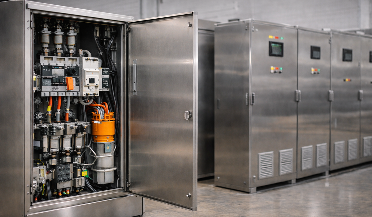
Other Auxiliary Components
- Battery: Used to supply power to control and protection equipment during a power outage.
- Battery Charger: Used to charge the battery.
- Control Panels: Used for remote control and monitoring of the switchgear.
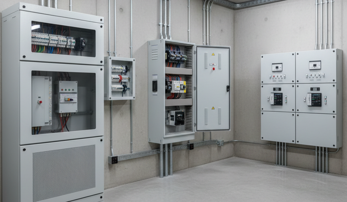
Low-Voltage Switchgear and Switchboards
Low-voltage switchgear operates up to 1000 V AC and sits downstream of the supply transformer, distributing to sub-boards and loads. It is what most people mean by “the electrical panel.”
Core protection and switching devices:
- MCB (miniature circuit breaker) — final circuit protection, thermal-magnetic operation
- MCCB (moulded case circuit breaker) — feeder protection, adjustable trip settings on larger frames
- ACB (air circuit breaker) — incomers and main ties, electronic trip units, drawout available
- MPCB (motor protection circuit breaker) — combined magnetic short-circuit and thermal overload protection for motor circuits
- Fuses — including current-limiting types where let-through energy must be reduced below a device’s withstand
- Contactors and thermal overload relays — motor switching and overload protection
- Phase failure and phase sequence relays — protecting three-phase motors from single-phasing and reversed rotation
- Surge protective devices (SPDs) — diverting transient overvoltage to earth
Push buttons, limit switches, micro switches, timers, float controllers and process sensors belong to control panels rather than to power distribution switchboards — different design discipline, different standards.
What Is an HV Room?
An HV room — also called a switch room, HV substation room or MV room depending on the site — is the dedicated enclosed space housing high- or medium-voltage switchgear inside a building or on a plant site. It exists because HV equipment cannot share space with general services.
What typically defines one:
- Restricted access. Locked, and entered only by authorised and qualified persons. Signage at every entry.
- Dedicated fire compartmentation, with fire rating to the surrounding structure.
- Working clearances in front of and behind the equipment sufficient for racking breakers out and for escape.
- Ventilation or cooling sized for the heat rejected by transformers and switchgear.
- Arc-fault pressure relief where arc-resistant switchgear is installed — the room must be able to accept the vented pressure, which frequently means a duct to outside or a relief panel.
- Earthing — a dedicated earth bar with connections to the building earthing system.
- No unrelated services. Water pipework, drainage and gas lines are kept out.
On many sites the HV room and the LV switchroom are separate spaces, with the transformer between them, either in its own compartment or outdoors.
Arc Flash and Internal Arc Safety: HV vs LV
Internal arcing faults are the destructive failure mode at every voltage class. What differs is the energy available and how the enclosure is expected to handle it.
At MV and HV, arc energy is high enough that containment is a design requirement, not an option. IEC 62271-200 classifies internal arc performance as IAC with accessibility type A (authorised personnel) or B (general public), followed by the protected sides — Front, Lateral, Rear — plus the tested arc current and duration, for example IAC AFLR 25 kA 1s. The North American equivalent is IEEE C37.20.7, which uses accessibility Types 1, 2, 2B and 2C.
At LV, arc energy is lower but far from harmless — a 480 V board with high available fault current can produce incident energy well above the threshold for serious burns. Arc-resistant LV switchgear exists, and arc-flash relays that detect the light flash in 1–2 ms are increasingly specified.
What the ratings do not cover. An arc-resistant rating is valid only with the enclosure closed and latched as tested. It says nothing about incident energy at the working distance for someone doing live work — that comes from an arc-flash study under IEEE 1584, with PPE per NFPA 70E.
On explosions specifically: the mechanism is an internal arcing fault, where the arc vaporises conductor material and the resulting pressure wave and hot gas do the damage. Prevention is a combination of correct maintenance (see condition of maintenance under NFPA 70B), correctly set protection that clears fast, arc-resistant construction, and interlocking that stops the wrong device being operated at the wrong time.
Low-Voltage Switchboard Design
- 1) Determine the switchboard type
- 2) Draw the switchboard diagram
- 3) Estimate the switchboard cost
Key factors in low-voltage switchboard cost estimation
- The cabinet dimensions required to accommodate the various elements inside the panel
- The quality, type, and quantity of the installed equipment and components
- Labor costs for manufacturing and assembling the low-voltage switchboard
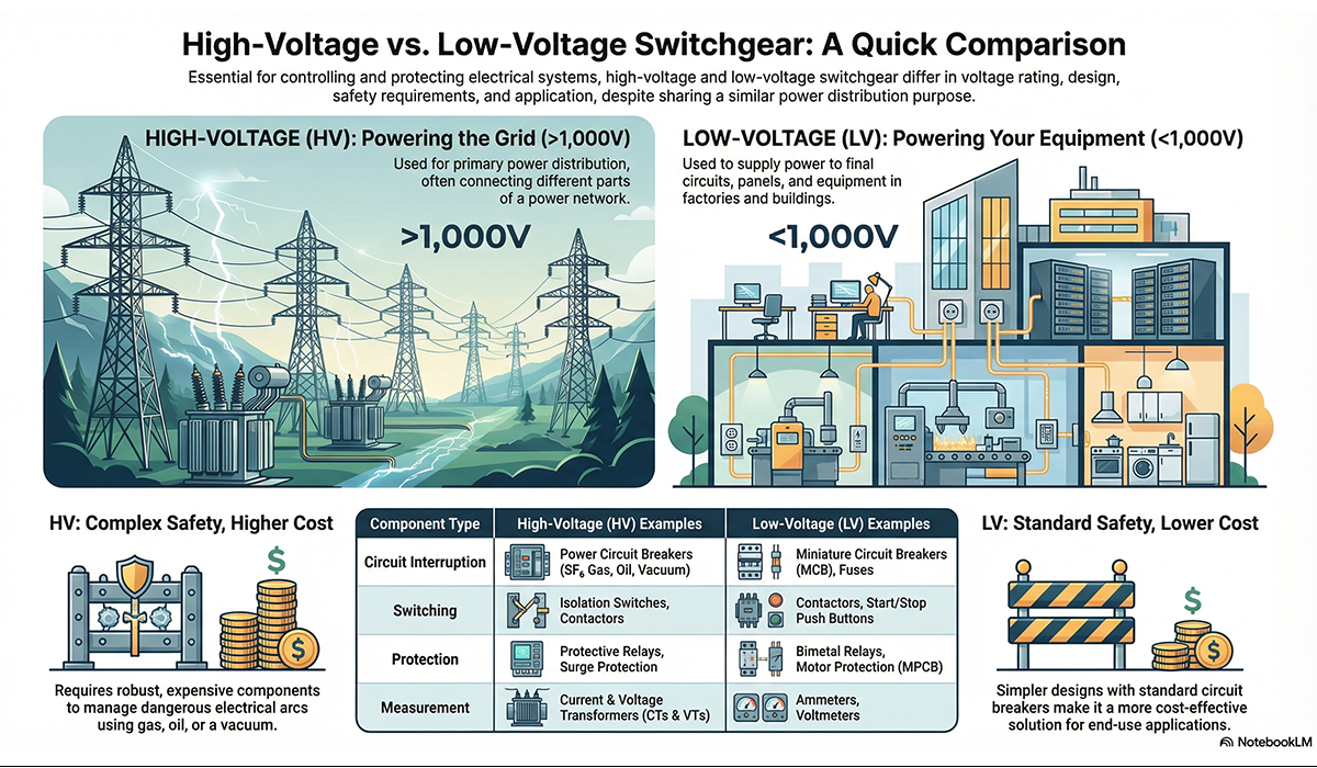
Differences Between HV and LV Switchboards
Both high-voltage (HV) and low-voltage (LV) switchboards are part of power distribution equipment, contain overload protection devices, and often function as service entrance equipment. So their overall purpose is similar. However, they differ in several important ways, which are summarized below.
- Voltage
- Safety
- Cost estimation
- Applications
Voltage
One of the main differences between HV and LV switchboards is voltage rating. HV switchgear voltage ratings cover a wider range and can vary from a few volts up to thousands of volts.
For example, low-voltage switchboards operate up to 1 kV, while medium-voltage and high-voltage switchboards can have voltage ratings up to 366 kV and above.
On the other hand, switchboards intended for lower voltages are often designed below 600 V. For example, a typical residential panel may be 120/240 V, while commercial and industrial installations may use panels rated up to 600 V.
Cost estimation
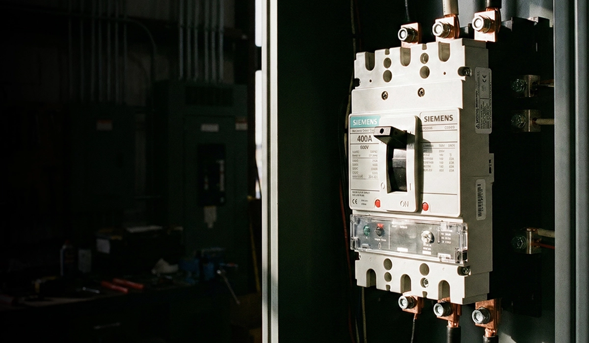
HV switchboards have more complex and robust structures, so they generally cost more than LV switchboards. For example, compared to fixed-mounted low-voltage MCCBs used in LV panels, HV switchgear may use withdrawable (draw-out) breakers, which are typically more expensive.
Where HV and LV Switchgear Belong in a Distribution System
These two are frequently described the wrong way round, so it’s worth being precise. Follow the power from the grid inward:
Transmission and primary distribution — HV. 100 kV and above, utility-owned, feeding bulk supply into substations. Gas-insulated or air-insulated outdoor switchgear. No part of this sits inside an office building.
Site incoming and internal distribution — MV. Typically 3.3 kV to 36 kV. This is the switchgear in a factory HV room, a hospital or data centre substation, a mine, or a campus distribution network. It feeds the primary side of on-site transformers and larger MV motors.
Downstream of the transformer — LV. Up to 1000 V. Main LV switchboards on the transformer secondary, then sub-distribution boards, motor control centres and panelboards. This is what serves homes, offices and shops — a residential consumer unit at 120/240 V or 230 V is the far end of this chain.
The simple rule: LV is on the load side of the final transformer, MV and HV are on the supply side. A building’s occupants only ever interact with LV equipment; the MV switchgear, where present, is behind a locked door in a dedicated room.
Choosing Between HV, MV and LV Switchgear
The voltage class isn’t usually a choice — it follows from what the utility supplies and how much power the site needs. What is a choice:
- Confirm the nominal voltage and name the standard. IEC 61439-2, IEC 62271-200, C37.20.1 or C37.20.2. “HV switchgear” alone produces non-comparable quotations.
- Get the prospective fault current from a study, not the transformer nameplate. It sets interrupting rating and internal arc requirements.
- Decide the maintenance model early. Drawout construction costs more up front and is the only way to maintain a device without dropping the bus.
- Specify internal arc performance to the room. An IAC AFLR rating needs a room that can accept the vented pressure — that’s a building design input, not a purchase decision.
- For EU MV projects, confirm the F-gas position for the voltage class and the in-service date.


Rate this article
Choose a rating from 1 to 5 stars.
No ratings yet