









Design Verification vs Routine Verification
Switchboard testing splits into two levels under IEC 61439-1, and confusing them is the most common mistake in specification and procurement.
A) Design verification (Clause 10) — performed once per design, on a representative sample. It establishes temperature rise, short-circuit withstand, dielectric strength, clearances and creepage. Some of these tests are destructive, which is why they are never repeated per order. The standard permits verification by test, calculation, or comparison with a verified reference design — physical testing is not mandatory for every clause.
B) Routine verification (Clause 11) — performed on every completed assembly before dispatch. It confirms that this particular unit matches the verified design and that workmanship has introduced no defects. It covers visual and wiring inspection, protective circuit continuity, dielectric testing, mechanical operation and functional checks.
The two answer different questions: is the design correct? and was this unit built correctly? Neither replaces the other. Asking a panel builder for a routine verification report on your order is reasonable; asking them to repeat a short-circuit type test for every unit is not.
If you are looking for more information about Electrical safety testing, it is recommended not to miss reading this article.
Design Verification Tests (IEC 61439-1 Clause 10)
Impulse Voltage Test
Switching operations and lightning produce transient overvoltages that the insulation system must survive. For low-voltage assemblies under IEC 61439-1, the rated impulse withstand voltage (Uimp) is typically 2.5, 4, 6, 8 or 12 kV, selected from the overvoltage category and the system voltage.
For medium-voltage switchgear under IEC 62271-1, the values are far higher: 75 kV for a 12 kV rating, 125 kV for 24 kV, and 170 kV for 36 kV. This test simulates lightning strikes or switching surges that can occur in power distribution systems, ensuring the switchboard insulation can withstand transient overvoltages.
Short-Circuit Current Withstand
Switchboards must withstand their rated short-circuit current. For instance, a switchboard rated for 50 kA short-circuit current must be able to handle fault currents up to this level without structural damage or fire hazard. This test ensures that busbars, connections, and enclosures remain intact during fault conditions.
Temperature Rise Withstand Test
The temperature rise of busbars and connection points due to the passage of rated current must be within the values introduced in the standard. IEC 61439-1 Table 6 gives no fixed temperature-rise limit for busbars. The limit is set by the mechanical strength of the conductor, the effect on adjacent equipment, the permissible temperature of insulating materials in contact with the bar, and the effect on devices connected to it. The 70 K figure in Table 6 applies to terminals for external insulated conductors, not to busbars themselves. A footnote permits up to 105 K for bare copper referenced to 35 °C ambient under defined conditions. Quoting a single number for busbar temperature rise is a common specification error. For example, a 630A busbar system in a switchboard supplying power to industrial motors must maintain safe operating temperatures even during peak load conditions.
Arc Ignition Withstand Test
For any reason, an arc may occur between busbars or different phases inside the switchboard. This arc increases the air pressure inside the cell; if no actions are taken, the cell door may be torn off and other cell parts may be thrown outward. This test is not mandatory but is critical for personnel safety in high-risk environments like substations and industrial facilities.
Arc faults inside an enclosure behave differently from series arcing in branch circuits, which is what arc fault breakers are designed to detect.
Testing of Circuit Breakers and Disconnectors
- Impulse test
- Short-circuit current withstand
- Temperature rise at contacts or their connection points to the busbar
For each switching device or circuit breaker, a breakable short-circuit current is considered, so that a withstand current test is also performed. If, at a point along the path, a fault occurs while closing the switch, the switch must be able to withstand this current, which is a multiple of the prospective short-circuit current set by the power factor of the fault. Under IEC 60947-2 the peak factor n rises with fault level — at 25 kA it is 2.1, so a 25 kA system requires a making capacity of about 52.5 kA peak. The 2.5 factor often quoted comes from medium-voltage practice under IEC 62271-100 at 50 Hz, and should not be applied to low-voltage equipment.
Basic Test
Routine verification is performed on every completed assembly before it leaves the factory. It covers the following:
A) General Inspections
Paint thickness, correct operation and integrity of door locks, correct adjustment of door gaps, switchboard degree of protection (IP), busbar color, completeness of bolts and nuts and correct selection of them, etc. For example, an IP54-rated outdoor switchboard must have properly sealed doors with gaskets intact, and all fasteners must be stainless steel or zinc-plated to prevent corrosion.
B) Mechanical Inspections
Correct operation of the switch and mechanical interlocks, inspection of insulators, continuity of the earthing system, smooth and correct movement of carriages, drawers, and other moving mechanisms, operation of drawer disconnectors. In a typical motor control center with 20 withdrawable contactors, each drawer must slide smoothly on rails and engage properly with the busbar stabs.
C) Electrical Inspections
Rated voltage and current, control circuit supply voltage, short-circuit current, correctness and quality of protective circuit implementation, electrical operation of all main switches, and the power-frequency test for the power circuit.
Switchboard Insulation Test
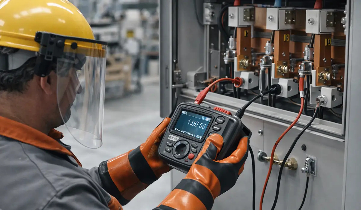
By insulation testing of electrical equipment, it is possible to detect insulation defects caused by mechanical damage, vibrations, excessive heat and cold, contamination, oil, moisture, and severe voltage changes. The devices used for insulation testing have the following specifications:
5 kV Digital Insulation Test
This device is used to test the insulation of high- and low-voltage electrical equipment. A typical megohmmeter applies test voltages of 500V, 1000V, 2500V, or 5000V and measures insulation resistance in megohms. IEC 61439-1 sets the acceptance criterion at 1000 Ω/V per circuit, referenced to the nominal voltage to earth — so a 230 V circuit must read at least 230 kΩ. Insulation resistance measurement is permitted as an alternative to the dielectric test during routine verification. In practice most project specifications set a much higher bar, commonly 10 MΩ or above, because a healthy new assembly should read far better than the standard’s floor.
Protective and Measuring Tests
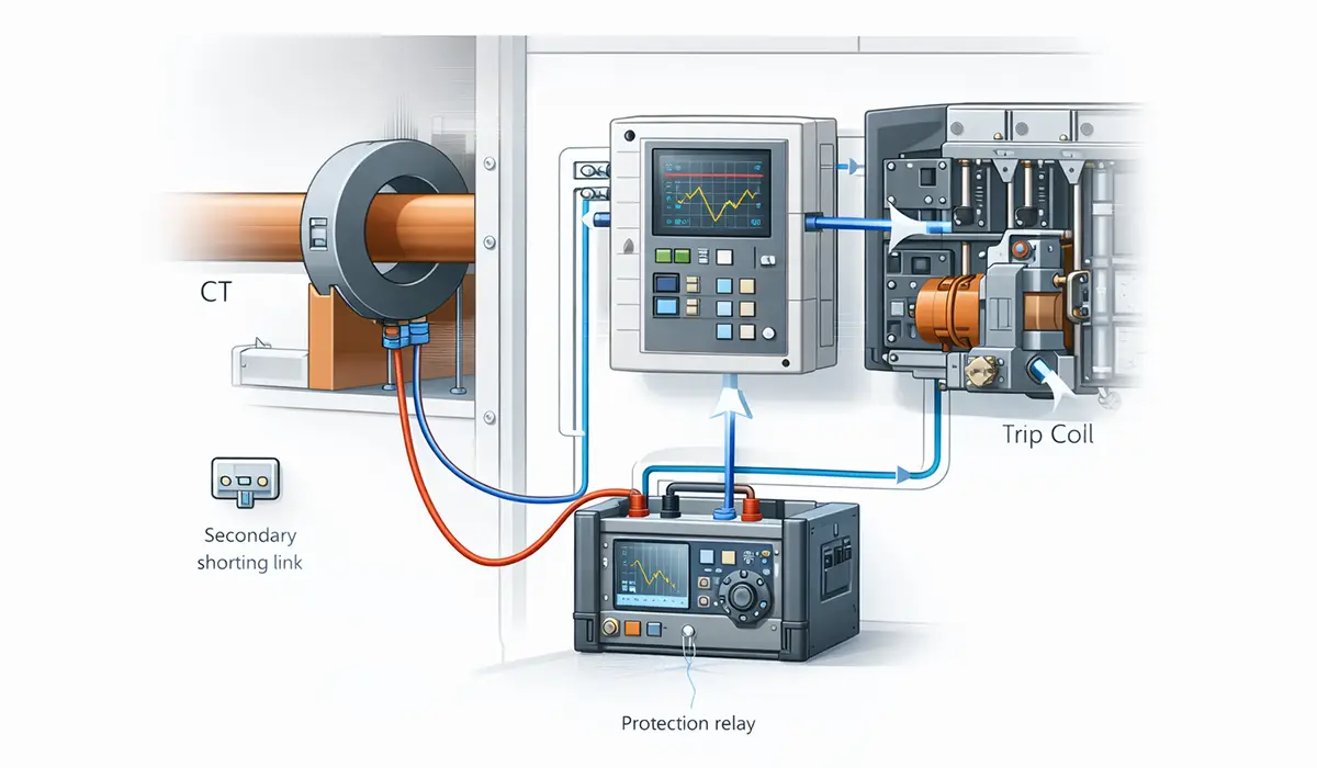
These tests are performed to check the performance of the protection system, including the current transformer and circuit breaker, or the voltage transformer and circuit breaker.
The measuring system test is performed to verify the performance of the current measuring system. A specified current is established using a primary current injection device and read through an ammeter. If the current transformer and ammeter are correctly selected and the connections are appropriate, the read value will be equal to the injected current value. For example, when injecting 100A through a 100/5A CT, the ammeter on the secondary side should read exactly 5A.
Primary Current Injection Test in the Switchboard
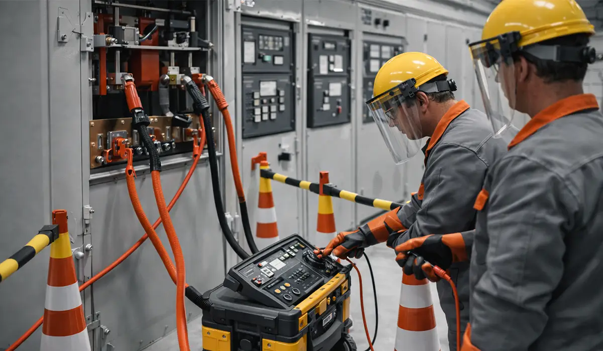
The primary current injection test in the switchboard is performed to check the performance of all components of the protection system. In this test, a high current is required for the operation of the protective device. The operating time of the protective relay is also measured. By performing this test, incorrect connection of the current transformer or incorrect relay setting can be identified.
The test of proper protection system performance, including the current transformer, relay, and circuit breaker, is carried out using a primary current injection device.
This test has several steps:
- Setting the relay overcurrent protection function
- Injecting primary current through the busbar box and increasing it from the relay setting system
- Recording the relay operating time
- Checking correct operation based on the relay setting system
By performing this test, any error in the current transformer connection, circuit breaker trip mechanism, or relay can be identified. For example, if an overcurrent relay is set to trip at 150A with a time delay of 0.5 seconds, the primary injection test should verify that when 150A is injected, the circuit breaker trips within the specified time window of 0.45 to 0.55 seconds.
| Test Parameter | Specification | Example Value |
|---|---|---|
| Injection Current Level | 1.2 to 3.0 times rated current | 180A for 150A setting |
| Operating Time Tolerance | ±10% of set time | 0.45-0.55 seconds |
| CT Ratio Verification | Within ±3% error | 200/5A ±0.15A |
| Test Duration | Until trip occurs | Maximum 5 seconds |
| Minimum Test Repeats | 3 successful tests | 3 consecutive passes |
Dielectric Test on Auxiliary and Control Circuits of the Switchboard
In performing this test, the secondary windings of the current transformer must be short-circuited and isolated from earth, and the secondary windings of the voltage transformer must be opened. In the power-frequency voltage test on auxiliary and control circuits, a voltage of 2 kV is applied for one minute between the auxiliary and control circuits of the switching device. The test result is acceptable if no electrical discharge occurs. In most cases, for the insulation (dielectric) test of low-voltage switchboards, it is used in two sections: electrical circuits and busbar power circuits. In the first section, 1 kV is applied, and in the second section, 2.5 kV is applied for one minute.
Secondary Injection: Testing Switchboard Relays
Primary injection proves the whole chain — CT, wiring, relay and breaker. Secondary injection tests the relay alone, by injecting a signal directly into its secondary terminals with the CT disconnected.
The two are complements, not alternatives:
- Primary injection pushes real current through the primary conductor. It verifies CT ratio, CT polarity, secondary wiring, relay setting and trip circuit together. It needs a high-current test set and takes longer.
- Secondary injection feeds a calibrated current or voltage straight to the relay inputs. It verifies pickup, timing curve, and element coordination quickly and repeatably — but it proves nothing about the CT or the wiring between CT and relay.
What secondary injection checks:
- Pickup value against the relay setting
- Operating time at several multiples of setting, plotted against the selected curve
- Instantaneous element threshold
- Directional element polarity where fitted
- Earth fault and negative sequence elements
- Trip output contact operation and target flags
Why both are needed. A relay can pass secondary injection perfectly while a reversed CT secondary makes the protection useless in service. Equally, primary injection alone rarely exercises the relay across enough points on its curve to prove coordination. Standard practice on commissioning is secondary injection to prove the relay characteristic, then primary injection to prove the installed chain end to end.
Record the as-found and as-left settings for every relay. Undocumented setting changes during commissioning are one of the most common causes of coordination failures discovered months later. This is where the discipline of overcurrent protection and device coordination either holds up or comes apart.
Switchboard Test by Measuring the Main Circuit Resistance
To measure the main circuit resistance, resistance measuring devices are used. The measured resistance shows the quality of the current path. Acceptance is normally expressed as a ratio rather than an absolute value, because a meaningful microohm figure depends entirely on bar cross-section and joint length. The usual criterion is that a bolted joint should present no more resistance than an equivalent length of solid busbar — a joint resistance ratio at or below 1.0.
High joint resistance means poor contact area, and poor contact area means localised heating that worsens over time as the joint oxidises. A joint reading several times its equivalent bar length needs re-torquing, cleaning of the mating faces, or both.
Joint quality is decided at fabrication, not at test — see how it is managed in busbar systems inside power switchboards.
Mechanical Performance Test of the Switchboard
During the mechanical performance test of the switchboard, the main circuit has no voltage and current. This test is performed to ensure proper operation of the switching device and other movable parts, and mechanical interlocks. This test is performed five times, and no adjustments are made during them. In this section, proper switching of the switching device such as the breaker is ensured while supplying the switching mechanism with critical boundary voltages. By checking wiring correctness, compliance of the wiring with the diagram is confirmed.
Mechanism design and the move to withdrawable construction are traced in this account of how modern switchgear evolved.
Switchboard Measuring System Test
To ensure correct operation of the switchboard measuring equipment such as voltmeter, ammeter, wattmeter, varmeter, power factor, transducers, etc., this operation is performed. For this purpose, first the current- and voltage-generating devices are set, then applied to the measuring system according to the electrical drawings of the switchboards, and the measured voltage and current values are indicated by the measuring equipment. The set values indicate the correctness of the measuring systems, and if the measured values do not match the applied voltage and current values, corrective action is taken to remove the fault in the measuring system.
Paint Thickness Control Test Using a Device on the Switchboard
The execution method is such that the device probe is placed at different points of the painted part and its thickness is measured. If the paint thickness is uniform on the part surface and matches the stated request, it is acceptable; otherwise, it is considered unacceptable and returned to the painting section.
Metering layout and compartment access vary widely by platform, as the CUBIC modular switchboard system shows.
Paint thickness control depends on their surface:
- Parts less than 10 square centimeters: one point
- Parts more than 10 square centimeters and less than 50 square centimeters: four points
- Parts with blind spots such as columns and frames: paint thickness is determined

Enclosure finish and corrosion protection are a specification decision as much as a QC one, as Rittal electrical panels and enclosures illustrate.
RAL Control TestThe color of switchboards for each project is selected based on the RAL chosen by the employer or the project manager, and the color of parts must be matched with the RALMETER. For this purpose, one of the painted parts that has a hole with a diameter of 10 mm or similar is placed on the RALMETER, and no color difference should be observed. Common RAL colors for industrial switchboards include RAL 7035 (light gray) for panel bodies and RAL 9005 (jet black) for doors.
This test must be performed at the start of painting on the first part of each project by the QC inspector, and if a difference is observed, action must be taken to correct it. In selecting a switchboard, environmental conditions, installation requirements, and protection conditions must be considered.
Table of Standard Cross-Sections of Copper Conductors Related to Test Current
| Actual Rated Current Range (A) | Cross-Sectional Area (mm²) | Thermal Rated Current (A) |
|---|---|---|
| 0 – 7.9 | 1.0 | 6 |
| 7.9 – 15.9 | 1.5 | 8 – 10 |
| 15.9 – 22 | 2.5 | 12 |
| 22 – 30 | 4 | 16 |
| 30 – 39 | 6 | 20 |
| 39 – 54 | 10 | 25 |
| 54 – 72 | 16 | 32 |
| 72 – 93 | 25 | 40 |
| 93 – 117 | 35 | 50 |
| 117 – 147 | 50 | 63 |
| 147 – 180 | 70 | 80 |
| 180 – 216 | 95 | 100 |
| 216 – 250 | 120 | 125 |
| 250 – 287 | 150 | 160 |
| 287 – 334 | 185 | 200 |
| 334 – 400 | 240 | 250 – 315 – 400 |
Notes:
- The current magnitude must be greater than and less than, or equal to, the value mentioned in the first level and the value mentioned in the second level.
- These values are recommended standard currents that are stated only for information.
- The distance between two parallel bars related to one terminal should be approximately equal to 5 mm.
- If connecting the mentioned bars to the device under test is not possible, using a bar that has the same cross-sectional area and whose width is equal to the terminal width will be permitted.
- Using cable instead of bar will be permitted. The permissible cross-sections related to the cable are under review.
Measuring Transformer
Current Transformer
Current transformers are equipment that convert large and unmeasurable line currents into a smaller current so that both protection and measurement can be performed. In the medium-voltage class, current transformers are often of the Cast Resin type. The main components forming a current transformer are: primary winding, secondary winding, core, resin.
For example, a 200/5 A current transformer is a transformer that converts 200 A in the primary to 5 A in the secondary, which will be a suitable current for measuring or protective equipment. Standard values for secondary current are 1 A and 5 A. In a typical industrial application, a 600/5A CT would be installed on the main feeder of a factory where the normal load is 480A, providing 4A to the ammeter and protection relay.
The core characteristics of a current transformer for measuring and protective purposes are different from each other. The core of a single-core current transformer can be suitable either for measuring equipment or for protective equipment.
The main specification of each core is its accuracy class. Common accuracy classes for measuring cores are 0.2, 0.5, and 1, which are specified as 0.2M5, 0.5M5, and 1M5. This means that our equipment will have, respectively, 0.2%, 0.5%, and 1% error at 5 times the rated current. Common accuracy classes for normal protective cores are 5P10, 10P10, and 5P15. For example, accuracy class 5P10 means that the transformer will have a 5% error at 10 times the rated current. For cores required for differential protection, the accuracy class is often 5P20, and their output power is 20 VA or more.
Example CT Nameplate Data:
- Ratio: 300/5-5A
- Core 1: CL 0.5, 10VA
- Core 2: 5P10, 10VA
In general, measuring equipment is selected based on rated current and does not have the ability to pass currents up to several times the rated current.
Effect of Thermal Current Ith
The amount of thermal current directly affects the cross-section of primary and secondary copper, and therefore creates a considerable effect on the transformer price. This effect is greater on the copper used in the secondary because the length of the secondary copper conductor has a very large number of turns. For instance, a CT rated for 1000A continuous thermal current will require significantly more copper in its windings than one rated for 400A, potentially doubling the material cost.
Voltage Transformer
Voltage transformers, like current transformers, reduce the voltage quantity in the power circuit to a level that is measurable and comparable for protective purposes. Unlike current transformers whose core characteristics are completely different depending on use in the measuring or protective circuit, protective and measuring cores of voltage transformers do not differ much from each other.
Therefore, a voltage transformer with accuracy class 0.5 can both provide a correct reading and be suitable for overvoltage or undervoltage protection. This is because voltage fluctuations in the network are very low (+0.5% to -0.5%). Voltage transformers can be connected between phase and earth or phase and phase. For example, a typical VT might have a ratio of 11000V/110V, stepping down the primary voltage by a factor of 100 for safe measurement and protection.
| Transformer Type | Accuracy Class (Measuring) | Accuracy Class (Protection) | Typical Application |
|---|---|---|---|
| Current Transformer (CT) | 0.2, 0.5, 1.0 | 5P10, 5P20, 10P10 | Metering and overcurrent protection |
| Voltage Transformer (VT) | 0.5, 1.0 | 3P, 6P | Voltage measurement and under/overvoltage protection |
| CT for Differential Protection | Not applicable | 5P20, Class X | Transformer and busbar differential protection |
Distribution Board Testing: What Differs
Distribution boards sit downstream of the main switchboard and are covered by IEC 61439-3 — the part of the series for distribution boards intended to be operated by ordinary persons. The verification framework is the same, but the scope is lighter.
What is normally reduced or omitted:
- Short-circuit withstand — often verified by the conditional rating of the upstream protective device (Icc) rather than by full Icw testing
- Temperature rise — commonly verified by calculation using device power losses rather than by test
- Arc containment — rarely applicable
What stays mandatory on every unit:
- Visual and wiring inspection against the schedule
- Protective circuit continuity — resistance between each exposed conductive part and the PE terminal must not exceed 0.1 Ω when tested at 10 A
- Dielectric test, or insulation resistance measurement as the permitted alternative
- Mechanical operation of devices and interlocks
- Correct labelling of every outgoing way
The most common field failure on distribution boards is not electrical at all. It is a circuit schedule that no longer matches what is actually connected, which turns every later fault-finding exercise into guesswork.
Conclusion
Low-voltage switchboards must be tested both after factory assembly and after site installation before commissioning, covering dielectric performance, temperature rise, short-circuit withstand, mechanical operation, protection continuity, and IP degree of protection. Design verification establishes what the design can do; routine verification confirms each unit was built to it. The procedures that matter most in practice are insulation testing, primary current injection for protection verification, and dielectric tests on auxiliary/control circuits. It also includes practical QC checks for paint thickness and RAL color matching, plus reference values for conductor cross-sections and measuring transformer accuracy classes. For reliable operation, these tests should be performed according to the specified test requirements and documented carefully.
Every one of these tests ultimately checks the same thing: whether the assembly was built the way the verified design says it should be. Busbar geometry, joint preparation and clearance accuracy decide most of the outcome before a test lead is connected. Explore PAYAPRESS CNC busbar fabrication machines for busbar processing that supports IEC 61439 verification.



Rate this article
Choose a rating from 1 to 5 stars.
No ratings yet