




If you’d rather listen than read, feel free to play the audio file below for the rest of this article.
What Is a Ring Main Unit?
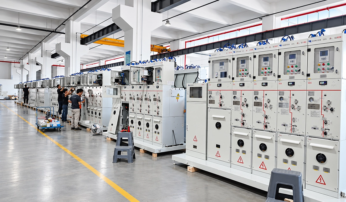
This switchgear is the switching point where a ring cable meets a distribution transformer. In short, it is the node that makes a looped network practical.
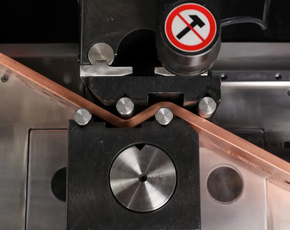
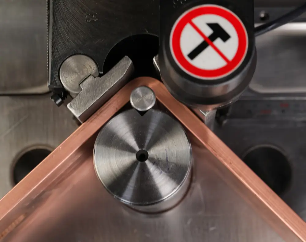
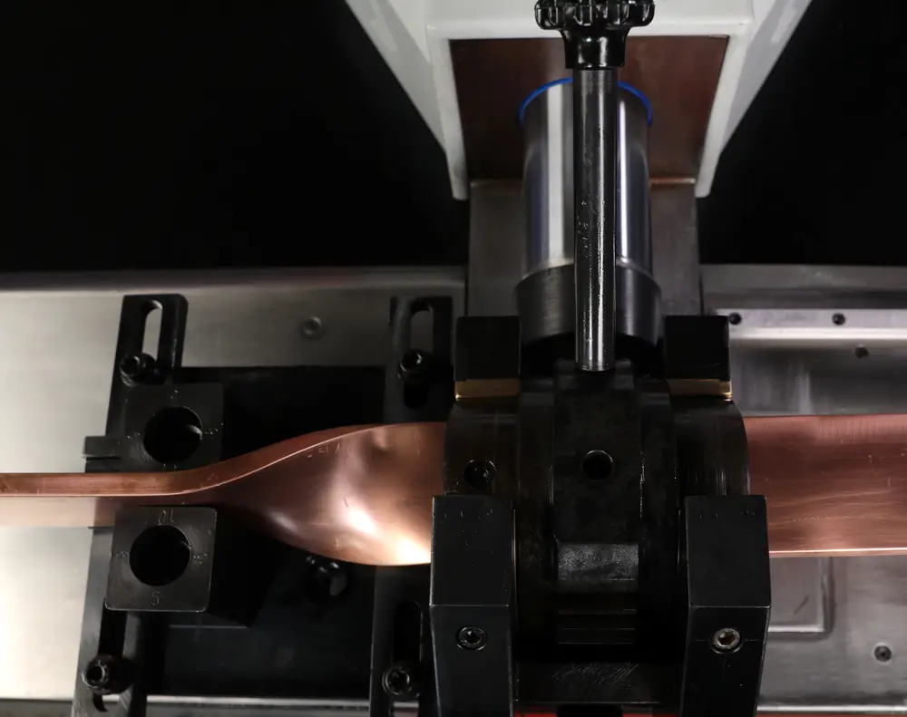
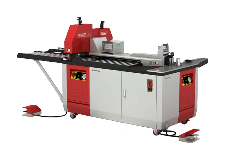
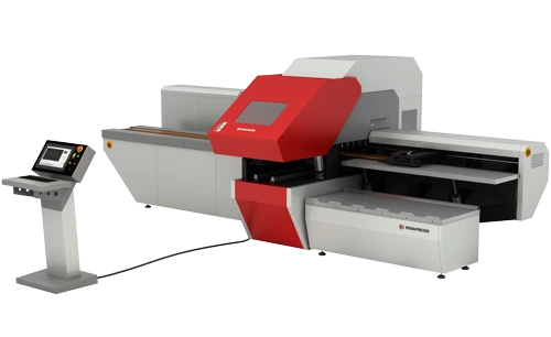
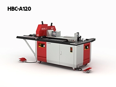
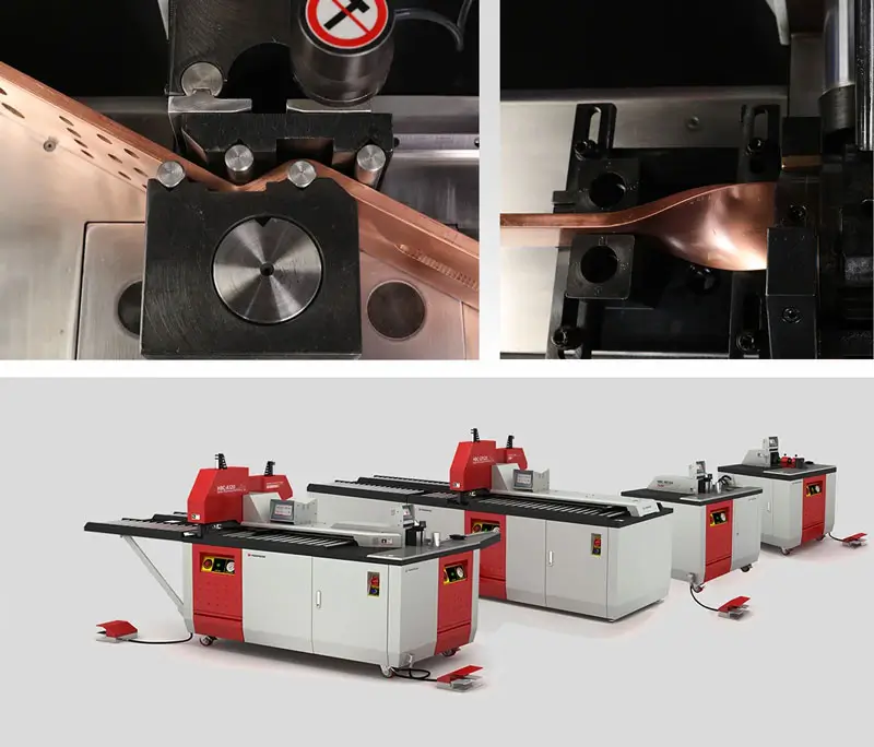
Designed for demanding busbar fabrication, the HBC-A160 three-in-one busbar machine processes copper and aluminum busbars up to 160 × 15 mm. Its independent cutting, punching, and bending stations support efficient production with accurate positioning.
Definition and Full Form
RMU stands for ring main unit. The name points to its place on the main cable ring, where it joins the ring cables to a transformer. The RMU full form is therefore a description of function, not just a label.
So, is an RMU low or medium voltage? It is medium voltage, not low voltage. It works above 1 kV, with common ratings of 12, 17.5 and 24 kV. As a result, it counts as medium voltage switchgear for secondary distribution, whereas low voltage boards serve the final circuits inside buildings.
Ring main units are only one member of a much larger switchgear family. For the bigger picture, start with our guide to electrical switchgear basics.
Ring vs Radial Networks
In a radial network, one feeder supplies substations in a line, so a cable fault cuts off every load downstream. In a ring network, the cable loops back to a second source, so each unit can receive power from either direction. Therefore, operators can isolate a faulty section and feed the loads from the other side.
This is the main reason utilities build rings in dense urban areas, where an outage affects many customers. However, a ring costs more cable than a radial line, so planners weigh reliability against cost. A simple diagram helps: draw two sources, a cable loop and one unit at every substation.
How a Ring Main Unit Works
The ring main unit working principle is simple: power flows through the unit in normal service, and switches cut out a section when needed. Each unit sits between two ring cables, and a third branch usually feeds a transformer.
The ring main unit function covers three tasks: switching, isolating and protecting.
Network operators run these loops with an open point and switch around faults, so the operating logic matters as much as the hardware. EEP’s guide explains open rings, fault passage indicators and remote switching in its urban networks guide.
Remote switching and automation are part of a wider shift in how switchgear protects networks. See how that role has changed in our article on modern switchgear evolution.
Normal Operation and the Normal Open Point
For a ring main unit working principle explained simply, start with the ring misconception. Many readers assume current circulates around the loop, but it does not. First, operators open the ring at one point, called the normal open point. Next, each half of the ring feeds its own substations from its own source. As a result, a fault on one half does not black out the other half. In contrast, a permanently closed loop would complicate protection in most networks.
Fault Isolation and Power Restoration
How does a ring main unit handle faults? A protection relay at the source trips, and fault passage indicators show crews which cable section failed. Next, operators open the switches on either side of that section, then close the normal open point so the healthy sections draw power from the other source. Crews then repair the cable while customers on the healthy sections stay supplied.
A transformer fault is different: the fuse-switch or breaker on that feeder clears it, and the ring stays energised.
Does an RMU restore power automatically? Not by default. Restoration may be manual, remote or automated, depending on the motor operators and control scheme installed. For example, a basic unit needs a crew on site, while an automated unit can reconfigure the ring through a remote command.
Main Components of an RMU
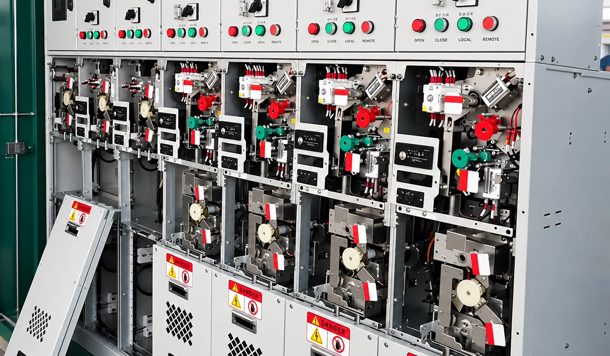
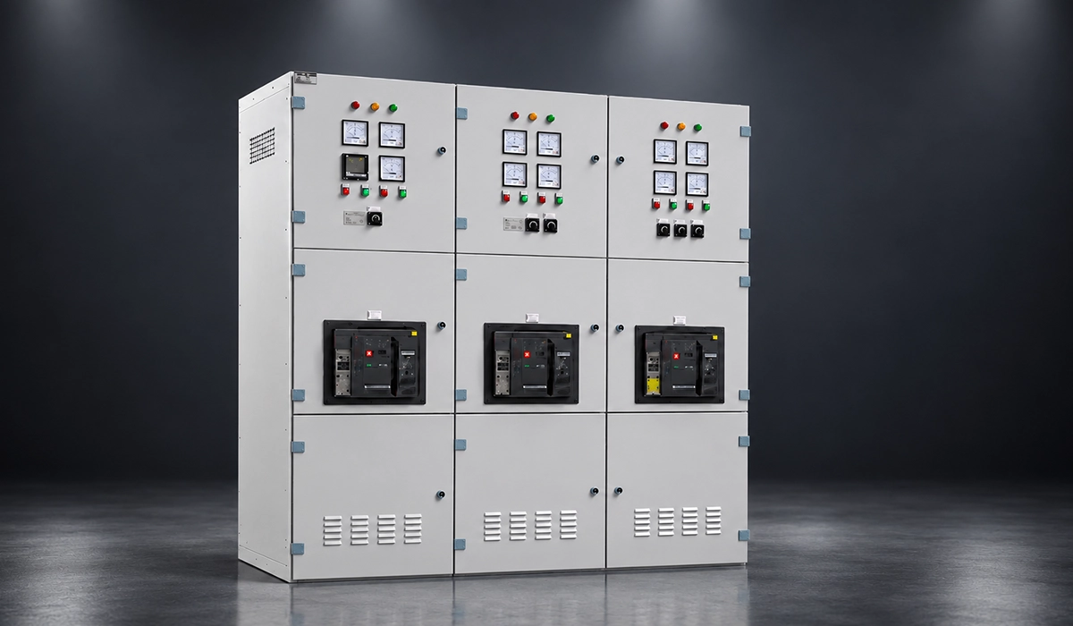
The ring main unit components sit in one metal-enclosed assembly. Each functional unit holds one of the devices below, and the busbar joins them.
| Component | Role |
|---|---|
| Load break switch | Switches cable current on the ring |
| Fuse-switch | Protects the transformer feeder |
| Vacuum circuit breaker | Clears faults on relay command |
| Earthing switch | Grounds a de-energised circuit |
| Busbar | Links all functional units |
| Bushings and cable boxes | Connect the cables |
| Insulation system | SF6, solid or air |
Switch ratings decide what each functional unit can safely make and break, so component choice should follow the governing standard. The IEC catalogue entry covers AC switches and switch-disconnectors from 1 kV to 52 kV in its IEC 62271-103 summary.
Many of these devices also appear in other low and medium voltage assemblies. Compare their roles in our overview of switchgear components.
Load Break and Three-Position Switches
A load break switch makes and breaks normal load current, but it does not clear short circuits. It can close onto a fault and carry fault current briefly, but it cannot interrupt it. In most designs, it is a three-position switch with closed, open and earthed positions. As a result, one mechanism prevents closing and earthing at the same time, which protects crews working on a cable.
Fuse-Switch and Vacuum Circuit Breaker
A fuse-switch combines a load break switch with high-voltage fuses, so it protects a transformer feeder at low cost. In addition, a striker on the fuse can open all three phases when one fuse blows. A vacuum circuit breaker, in contrast, trips on relay signals and clears faults repeatedly. Therefore, fuse-switch feeders suit smaller transformers, whereas breaker feeders suit larger ones or tighter protection.
Busbars, Earthing and Bushings
Busbars are the copper bars that link every functional unit inside the enclosure. Designers size each bar by cross-section against temperature rise and short-circuit stress, so the ring main unit busbar rating must cover the continuous current and the short-time withstand current of the whole board. Copper offers high conductivity and strength, while aluminium is lighter but needs a larger cross-section for the same current.
Fabrication quality matters as well: precise holes and bends keep clearances, joint pressure and bar-to-bushing alignment correct. Correct bend radii also protect the bar from cracks and thinning. The earthing bars and earthing switch complete the safety path, so the same accuracy applies to them.
Insulation: SF6, Solid and Air
SF6 gas gives a compact enclosure, but SF6 is a potent greenhouse gas that needs careful handling. Solid insulated designs avoid the gas and typically need little maintenance. Air insulated units use ordinary air, so there is no gas to monitor, but larger clearances raise the enclosure size. For an SF6 vs solid insulated ring main unit choice, therefore, compare footprint, gas handling and life-cycle cost.
Types of Ring Main Units
Types of RMU differ in four ways: extensibility, insulation, transformer feeder protection and location.
Extensible units accept extra modules at the side, so a utility can add a feeder later without replacing the board. In contrast, non-extensible units arrive as a fixed block, which is cheaper and smaller.
RMU vs conventional switchgear is a fair comparison. A ring unit is compact and factory assembled for secondary substations, whereas conventional switchgear uses separate panels and suits large primary substations. RMU switchgear is usually sealed and type tested, which suits unattended sites.
| Classification | Option A | Option B |
|---|---|---|
| Extensibility | Extensible: add units at the side | Non-extensible: fixed layout |
| Insulation | Gas or solid: compact | Air: larger, simple |
| Transformer feeder | Fuse-switch: lower cost | Vacuum circuit breaker: relay protection |
| Location | Indoor: substation room | Outdoor: weatherproof enclosure |
Insulation choice now carries regulatory weight as well as technical weight, especially for new projects in Europe. For example, Schneider Electric’s RM6 page warns that EU F-gas rules restrict new SF6-based medium-voltage equipment from 2026 in its RM6 F-gas notice.
Conventional switchgear for larger substations often uses a metal-clad design with withdrawable breakers. Learn how that layout differs in our guide to metal-clad switchgear.
Where RMUs Are Used
RMU application starts with utilities, which use the units in secondary distribution to feed street-level transformers from a cable ring. However, the same ring logic suits many other sites:
- Industrial plants: a ring supply keeps process areas running when one cable fails.
- Solar and wind: collector cables from several turbines or inverter stations connect through ring units.
- Data centers: dual feeds support continuity of supply.
- Commercial buildings: compact units fit basement substations.
Wind farms and package substations use the same ring logic, but each has its own layout and protection needs. For example, a wind turbine tower often holds a compact unit at its base, whereas a package substation puts the unit, transformer and low voltage board in one housing.
Manufacturer application lists show how widely the same ring logic travels beyond utility networks. ABB names distribution, renewables, buildings, data centers, industry and transport among its target sectors in its SafeRing application overview.
Behind each of these applications sit busbars that carry current between the switching devices. Our article on the role of busbars explains why they matter in modern electrical systems.
How to Select a Ring Main Unit
Selection starts with the network, then moves to the equipment. Work through this checklist in order:
- Voltage: choose rated and impulse withstand levels above the network maximum.
- Current: size ring switches and busbars for load plus growth.
- Short-circuit rating: match the short-time withstand current and duration to the site fault level.
- Insulation: weigh SF6, solid or air against footprint, gas handling and maintenance.
- Configuration: count ring and feeder units, and choose an extensible design if growth is likely.
- Internal arc classification: choose the class that suits the room layout and operator access.
- Automation readiness: check for motor operators, auxiliary supply and space for remote control.
Finally, confirm that the unit is type tested to IEC 62271-200, and request the test certificates. Ask for reports on the exact configuration, not only on a similar one. Also confirm the rated values on the nameplate.
Internal arc tests, for example, depend on the room, so compare the test setup with the real substation before ordering.
Selection errors are costly to fix after installation, so the type-test standard should define the checks. The IEC catalogue entry sets the scope for AC metal-enclosed switchgear from 1 kV to 52 kV, including internal arc testing, in its IEC 62271-200 summary.
The same selection logic also applies to low voltage boards and larger switchgear lineups. For a broader checklist, see our switchgear selection guide.
Installation, Maintenance and Safety
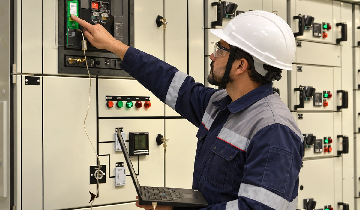
First, check the foundation and cable entries before commissioning. Next, confirm earthing continuity, gas density indication where fitted, and correct interlock operation. Then test the insulation and operate every earthing switch.
Interlocks prevent unsafe switching sequences, so never bypass them. Because the unit is metal-enclosed, crews should also confirm that all covers and cable compartments are closed before energising. Inspection intervals follow manufacturer guidance and depend on insulation type, duty and environment.
At handover, record the settings, torque values and test results, so later maintenance can compare against them. Training also matters, so operators should practise the switching sequence before the first energisation.
Safe work practice matters as much as the hardware, so published safety guidance should shape every procedure. The UK regulator’s guide covers the selection, operation and maintenance duties of switchgear owners in its HSE switchgear guidance.
Good maintenance records also help you get more from the equipment over its service life. Find practical tips in our guide to optimizing switchgear performance.
Conclusion: Ring Main Unit
An RMU links a cable ring to its transformers and lets operators isolate a fault without a wide outage. It is medium voltage, and restoration may be manual, remote or automated, depending on the scheme. When selecting one, check ratings, insulation, internal arc class and busbar quality, then follow manufacturer guidance for service.
Busbar quality came up throughout this guide, from ratings to fabrication. Learn more about how busbars in switchgear keep current flowing between every device.


Rate this article
Choose a rating from 1 to 5 stars.
No ratings yet