

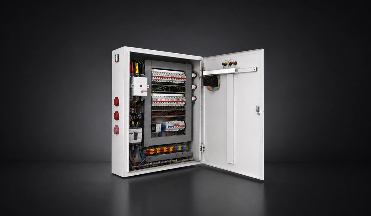





Why Switchgear Selection Is One of the Most Critical Electrical Decisions You Will Make
Choosing the right switchgear for your facility starts with one rule: treat switchgear as a system decision, not a catalog purchase. The lineup sits between sources, protective devices, and loads, so a poor choice in ratings or construction spreads risk into safety, uptime, and future capital work. This guide builds on our broader switchgear standards resource, which covers the full compliance landscape for busbar and switchgear systems.
At design stage, the most expensive errors are usually invisible at first: understated fault duty, the wrong standards family, no room for extension, weak maintainability, or a construction type that forces unnecessary outages later. Those problems surface only when the facility expands, faults, or needs service under pressure.
In practice, switchgear specification criteria are interdependent. Voltage class drives product family; available fault current drives survival ratings; current demand drives thermal sizing; environment drives enclosure and derating; and maintenance philosophy drives fixed versus draw-out construction.
A reliable switchgear buying guide for engineers therefore covers at least these linked decisions: voltage level, fault duty, continuous current, codes and standards, insulation technology, construction type, environment, arc flash, automation, and total cost of ownership. That is the framework used below.
For offline reading, you can download the complete document from this link.
Step 1 — Determine Your System Voltage Level
Voltage is the first filter because it determines the switchgear family, insulation coordination, test basis, and often the utility interface. A facility served entirely at low voltage is procured and maintained very differently from one with medium-voltage incoming distribution.
The table below summarizes the core bands designers use first. IEC 61439 covers low-voltage assemblies up to 1,000 V AC or 1,500 V DC, while IEC 62271-200 applies to AC metal-enclosed switchgear above 1 kV and up to 52 kV. In North America, LV projects commonly reference UL 891 and, for metal-enclosed low-voltage power circuit breaker switchgear, UL 1558.
| Voltage Band | Typical Facility Range | Common Governing References |
|---|---|---|
| Low Voltage (LV) | Up to 1,000 V AC / 1,500 V DC | IEC 61439, UL 891, UL 1558 |
| Medium Voltage (MV) | Above 1 kV; Often up to 36 kV in Facility Work | IEC 62271-200, IEEE C37 Family |
| High Voltage (HV) | Above Typical MV Building-Distribution Practice | Dedicated HV Switchgear / Substation Practice |
For additional technical context, refer to this external reference page.
Low Voltage vs Medium Voltage — Making the Right Call
Asked plainly, MV vs LV switchgear which is right for my facility depends on service voltage, load concentration, distribution distance, and utility supply arrangement. If the site is served and distributed at LV, LV switchboards or metal-enclosed LV switchgear may be enough. If the utility delivers MV or the site uses campus-style distribution, MV incoming gear plus downstream LV distribution becomes the normal architecture.
Save this downloadable resource for quick access whenever you need it.
Nominal Voltage and Equipment Voltage Rating
Do not confuse system nominal voltage with equipment rated voltage. Engineers specify against the highest voltage the switching equipment may see in normal service, not just the nameplate nominal. In other words, the distribution gear must be rated for the real system envelope, including normal variation and the relevant standard’s service conditions.
Access the full file here to review all technical notes, examples, and recommendations.
Getting these voltage bands right early prevents costly redesigns later in the project. For a broader look at how these references fit together, see our electrical standards guide.
Step 2 — Determine the Available Fault Current at Your Installation Point
Once voltage class is set, fault duty becomes the gating safety parameter. Continuous current tells you what the lineup can carry thermally; available fault current tells you whether it can survive and interrupt a real fault without catastrophic failure.
Use these terms consistently in specifications and submittals. IEEE 551 centers short-circuit duties; IEC and manufacturer data then express the withstand and interrupting limits that the assembly or device must meet.
| Parameter | Meaning | Why It Matters |
|---|---|---|
| AFC / Prospective Short-Circuit Current | Maximum Fault Current Available at the Point of Installation | Sets Minimum Interrupting / SCCR Requirement |
| Icw / Ik | Short-Time Withstand Current | Defines What the Assembly Can Endure for a Stated Duration |
| Ipk | Peak Withstand Current | Covers First-Half-Cycle Electrodynamic Stress |
| Icc / Conditional Rating | Withstands with a Specified Protective Device | Matters Where Current-Limiting Protection Is Part of the Solution |
This external page provides additional insights that may help with your evaluation.
Why Available Fault Current Is the Most Safety-Critical Parameter
If someone asks, how does available fault current affect switchgear selection, the answer is direct: it sets the minimum interrupting rating, bus bracing, and short-time withstand requirement. In U.S. practice, NFPA materials related to NEC development emphasize that switchboards, switchgear, and panelboards must not be rated below the available fault current at the point of supply, with field-marking requirements centered on that value.
How to Determine AFC — The Power Systems Study
Do not estimate AFC from transformer kVA alone. A proper short-circuit study uses utility data, transformer impedance, cable impedance, rotating-machine contribution, and protection settings. It should be revised when the system configuration changes materially, and the highest fault current is often at or near the main bus rather than downstream feeders.
This source can help you verify the information and continue your independent research.
Ratings that look correct on paper can still fail under real fault conditions if the assembly was never rigorously tested. Our overview of type tests explains what these ratings actually verify.
Step 3 — Establish Continuous Current Requirements and Future Load Growth
Thermal sizing answers a different question from fault duty: how much current can the assembly carry continuously, at the real ambient conditions, without overheating. A sound switchgear selection factors checklist therefore separates current-carrying capacity from short-circuit survival.
Sizing the Main Bus for Present and Future Load
To answer how to specify switchgear voltage and current ratings correctly, start with a formal load calculation under the project’s code basis, then apply diversity and operational duty honestly. Engineers should size the main bus for credible demand, not just day-one connected load, and many teams reserve explicit growth headroom as an engineering convention rather than a universal code requirement.
You can download the full report here to review the topic in greater detail.
Spare Way and Expansion Planning
If the client is asking how to future-proof switchgear selection for facility expansion, the cheapest answer is usually spare ways, blank spaces, extension capability, and room geometry reserved on day one. Modular sections and withdrawable construction simplify later additions; retrofitting after commissioning usually costs more and can force outages or civil rework. As an engineering convention, many teams reserve roughly 20–25% spare capacity for foreseeable growth, but that margin should be justified against phasing and load uncertainty.
The complete resource file is available here for offline reading and comparison.
Bus and feeder sizing is only as reliable as the cable ratings behind it. Learn more in our guide to three-phase power cable sizing.
Step 4 — Identify the Applicable Standards and Codes
Standards selection is not paperwork. It defines construction rules, type tests, markings, verification, and the supplier universe you can competitively bid. It also shapes what an AHJ, utility, insurer, or owner’s engineer will accept without exceptions.
The regional pattern is straightforward, even if export projects complicate it. International and European LV assemblies usually point to IEC 61439, MV metal-enclosed gear to IEC 62271-200, and North American LV projects commonly center on UL 891 or UL 1558, with MV work in the IEEE C37 family.
| Region / Context | LV Focus | MV Focus |
|---|---|---|
| Europe / International | IEC 61439 | IEC 62271-200 |
| North America | UL 891 / UL 1558 | IEEE C37.20.x |
| Dual-Compliance Export Work | Project-Specific Mix | Project-Specific Mix |
IEC vs ANSI/IEEE — Which Standards Apply to Your Project?
The practical answer to IEC vs ANSI switchgear standards which applies to my project is geography plus owner requirements. International projects usually specify IEC language first. North American projects tend to specify UL for LV product compliance and IEEE/NEMA conventions for MV construction and testing. Dual-compliance projects are feasible, but they narrow vendor choice and often increase cost, footprint, and lead time.
Visit the linked website to better understand the background, standards, and practical use cases.
Local Code and AHJ Requirements
Product-standard compliance is necessary but not sufficient. The adopted installation code, utility service rules, insurance requirements, and the authority having jurisdiction can add working-space, marking, service-entrance, documentation, or safety obligations. That is why “listed” or “IEC-compliant” should never be the final review step.
Meeting the letter of a standard is not the same as passing design verification testing. Our guide to IEC 61439 verification walks through what that process involves.
Step 5 — Select the Insulation Technology
Insulation technology changes footprint, maintainability, environmental profile, and future compliance exposure. For many projects, the real comparison is air-insulated versus gas-insulated architecture, with vacuum interruption and SF6-free alternatives sitting inside that decision.
Air-Insulated Switchgear (AIS)
AIS remains the default for many industrial rooms because it is familiar, accessible, and usually less expensive upfront than GIS. The trade-off is footprint: more room is needed for compartment geometry, access, and clearances, so AIS is strongest where space is available and maintainability outranks compactness.
Gas-Insulated Switchgear (GIS) and SF6-Free Alternatives
GIS is attractive where the electrical room is constrained because it is markedly more compact than AIS. But the sustainability and compliance side now matters much more: Regulation (EU) 2024/573 tightens F-gas controls, and major OEMs are already offering Clean Air and other SF6-free solutions for new MV projects with long asset lives.
Vacuum Switchgear
Vacuum interruption is the mainstream choice for modern MV breakers. It extinguishes the arc inside sealed vacuum bottles, avoids greenhouse-gas handling obligations, and offers long service life with relatively low maintenance burden. For most new MV specifications, vacuum is the default starting point unless project conditions justify another architecture.
Insulation choices are inseparable from how a system handles overvoltage and contamination exposure. See our explainer on pollution degree and overvoltage categories.
Step 6 — Choose Between Fixed and Draw-Out Construction
Construction type determines how the switchboard or switchgear will be maintained, tested, modified, and restored over decades of service. The cost delta is real, but so is the operational difference during outages, troubleshooting, and live-facility maintenance.
The comparison below is the one most owners actually care about: outage dependence, maintenance access, and continuity of operation. In critical facilities, this fixed versus draw-out decision often matters as much as the breaker brand.
| Decision Factor | Fixed Construction | Draw-Out Construction |
|---|---|---|
| Initial Cost | Lower | Higher |
| Maintenance Flexibility | Lower | Higher |
| Need for De-Energization | More Likely | Reduced for Many Tasks |
| Testing Convenience | Limited | Strong |
| Typical Fit | Non-Critical or Outage-Tolerant Systems | 24/7, Critical, Frequently Modified Systems |
Fixed Construction — When It Is Appropriate
Fixed-mounted construction is appropriate when the facility has planned shutdown windows, the role is not mission-critical, and simplicity matters more than live maintainability. It is mechanically simpler and less expensive, but service or replacement work usually requires de-energizing the affected section, so outage planning becomes part of the maintenance model.
Draw-Out Construction — When It Is Justified
If a buyer asks, what is the difference between fixed and draw-out switchgear and when to use each, the answer is disconnectability and maintainability. Draw-out breakers can move through connected, test, disconnected, and removed positions, enabling testing, replacement, and some maintenance without taking down the whole lineup. That premium is easiest to justify in data centers, hospitals, and continuous-process plants.
Construction quality is just as decisive as the choice between fixed and draw-out designs. Our page on busbar manufacturing compliance covers how that quality is verified.
Step 7 — Define Environmental and Installation Requirements
Environmental service conditions can change both the enclosure specification and the usable ratings. This is where indoor versus outdoor service, contamination, corrosion, temperature, and altitude stop being site notes and become real design constraints.
Indoor vs Outdoor Installation
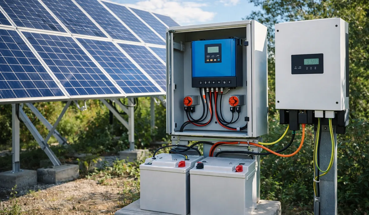
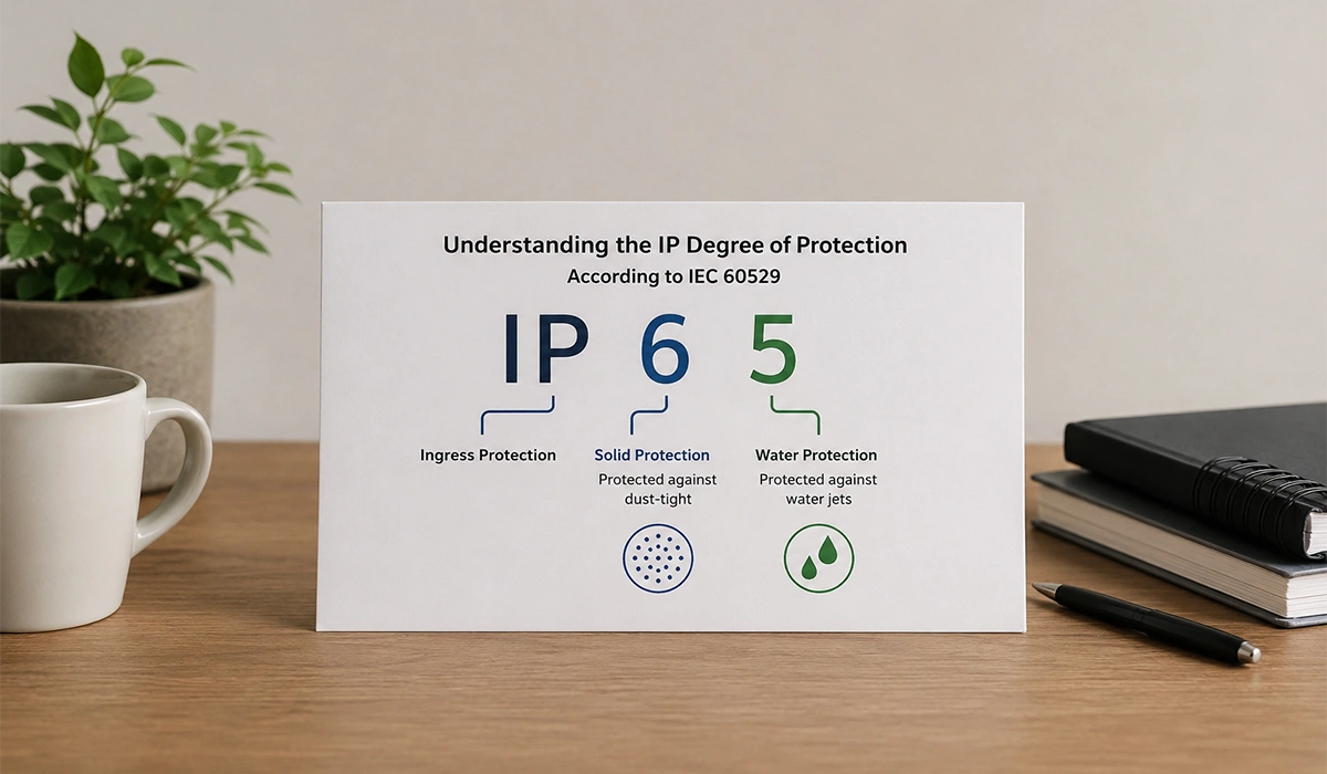
Indoor versus outdoor switchgear selection starts with location but does not end there. Clean indoor electrical rooms can use relatively modest enclosure protection, while dust, wash-down, salt, UV, direct weather, or chemical exposure push designers toward higher IP protection, corrosion-resistant materials, and packaged or prefabricated outdoor solutions.
Altitude, Temperature, and Special Environments
Above about 2,000 m, reduced air density lowers dielectric strength and cooling performance, which can force derating. High ambient temperature can do the same. Manufacturer guidance also routinely ties standard ratings to roughly 40 °C ambient and standard altitude limits, so seismic zones, hazardous areas, or unusual climates should trigger project-specific qualification instead of default catalog assumptions.
Hazardous locations add another layer of enclosure and certification requirements beyond standard IP ratings. Our comparison of ATEX vs IECEx explains how zones and marking differ.
Step 8 — Address Arc Flash Safety Requirements
Arc-flash results are not an afterthought. They can change the switchgear specification itself by shifting the preferred construction, protection scheme, relay features, and maintenance method. That makes arc flash a design input, not merely a labeling exercise at the end.
Performing the Arc Flash Study
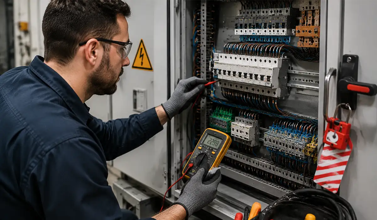
An IEEE 1584 study converts fault current, clearing time, equipment type, and working distance into incident energy. If the result is too high, the answer is not only PPE; it may require faster protection, a different construction philosophy, or a different maintenance approach. NFPA 70E then governs how the hazard is managed in the workplace.
Arc Flash Mitigation Features to Specify
Useful mitigation features include light-and-current arc detection, zone-selective interlocking, maintenance switches or maintenance mode, arc-resistant construction, and remote switching or remote racking. SEL and major OEM guidance converge on the same principle: reduce clearing time and keep people outside the arc-flash boundary wherever practical.
Getting the incident-energy calculation right is only useful if the resulting labels meet current requirements. Our quick reference on arc flash labeling covers what NFPA 70E and IEEE 1584 expect.
Step 9 — Evaluate Automation and Communication Requirements
Modern switchgear is no longer only protective hardware. It is also a communications node for SCADA, energy management, power quality, alarm handling, and sometimes remote control. If those requirements are real, they must be specified at procurement stage rather than bolted on later.
SCADA Integration and Smart Switchgear
For MV systems, IEC 61850 remains the reference framework for interoperable digital substations, with MMS and GOOSE central to many protection and control schemes. LV monitoring still commonly uses Modbus RTU/TCP, and DNP3 appears in utility-facing applications. Cybersecurity should be specified explicitly, using standards such as IEC 62351 and IEEE 1686 for connected IED environments.
Metering and Power Quality Monitoring
Specify metering before the switchgear is built. IEC 61557-12 covers power metering and monitoring devices for AC and DC distribution systems, and the CT/PT ratios, accuracy class, burden, and logging objectives should match the real use case: billing, energy management, protection, or power quality diagnostics.
Adding communication capability to switchgear also raises electromagnetic compatibility concerns that shouldn’t be an afterthought. Our guide to EMC requirements outlines what IEC 61000 requires.
Step 10 — Evaluate Total Cost of Ownership (TCO)
How to choose the right switchgear for your facility is often answered badly when procurement stops at CAPEX. Switchgear lives for decades, so the comparison that matters is lifecycle cost under real maintenance, outage, energy-loss, and end-of-life conditions.
Use a simple TCO frame rather than headline price alone. IEC 60300-3-3 treats lifecycle costing as part of dependability management, which is exactly the right lens for switchgear that may operate for 25 years or more.
| Cost Category | Typical Drivers | Often Higher for |
|---|---|---|
| CAPEX | Equipment, Installation, Commissioning | Draw-Out, GIS, Arc-Resistant, Highly Digital Gear |
| OPEX — Losses | Resistive Losses, Poor Contact Health | Undersized or Poorly Maintained Systems |
| OPEX — Maintenance | Labor, Testing, Consumables, Specialized Handling | Fixed Construction, Complex Gas-Handling Regimes |
| OPEX — Downtime | Lost Production During Outages | Outage-Dependent Maintenance Models |
| End-of-Life | Disposal, Recovery, Replacement Strategy | Regulated Gas-Based Equipment |
CAPEX vs OPEX — Beyond the Purchase Price
A lower purchase price can lose badly once losses, spare parts, service labor, outage cost, and decommissioning are counted. In critical facilities, draw-out construction, diagnostics, and SF6-free technology often look expensive upfront and rational over the full operating life because they lower maintenance friction, compliance risk, or downtime exposure.
Vendor Evaluation Criteria Beyond Specifications
Vendor review should go beyond a compliant datasheet. Ask for accredited type-test evidence, local service reach, spare-parts horizon, installed base in similar duty, FAT/witness capability, and cyber posture for connected relays and meters. On digitally enabled switchgear, long-term support and security capability can matter as much as breaker ratings.
Switchgear Selection Summary — A Quick Decision Framework
How to choose the right switchgear for your facility becomes manageable when you reduce it to ten linked decisions: voltage, fault level, current, standards, insulation, construction, environment, arc flash, communications, and lifecycle cost. That is the shortest route from abstract requirements to a defensible procurement package.
The checklist below is the shareable version of the whole method. Use it as a pre-bid review sheet before issuing RFQs or approving vendor deviations.
| Selection Parameter | Key Question | Decision Impact |
|---|---|---|
| System Voltage | LV or MV? | Determines Product Family and Standard Path |
| Available Fault Current | What Does the Short-Circuit Study Show? | Sets Minimum Interrupting / SCCR and Withstand Duty |
| Continuous Current | What Is Real Demand Plus Growth? | Sizes the Main Bus and Feeders |
| Standards | IEC, UL, IEEE, or Dual Compliance? | Narrows Acceptable Suppliers and Tests |
| Insulation Technology | AIS, GIS, Vacuum, or SF6-Free? | Changes Space, Maintenance, and Compliance Exposure |
| Construction Type | Fixed or Draw-Out? | Defines Outage Model and Maintainability |
| Environment | Indoor / Outdoor, Contamination, Altitude, Temperature? | Drives Enclosure and Derating |
| Arc Flash | What Incident Energy Is Acceptable? | May Require Mitigation Features |
| Automation | SCADA, Metering, Protocols, Cybersecurity? | Shapes Devices and Communications Scope |
| TCO | What Is the 25-Year Cost, Not Just CAPEX? | Often Changes the Ranking of Options |
A disciplined answer to these ten questions is far more reliable than brand-first selection. It also produces cleaner specifications, fewer technical deviations, and a better basis for owner approval.
Reducing long-term losses often comes down to smaller power-quality fixes that pay for themselves over time. Our guide to capacitor bank capacity shows how that calculation works.
Conclusion
Selecting switchgear correctly is not about choosing the most familiar product or the lowest bid — it is about matching the equipment to the real electrical, operational, and regulatory conditions of the facility. When engineers evaluate voltage level, available fault current, continuous current, standards compliance, insulation technology, construction type, environmental conditions, arc flash mitigation, automation needs, and total cost of ownership as one integrated decision set, they reduce technical risk and make the final specification far more durable over the asset’s 25- to 30-year life. In practice, the best switchgear choice is the one that protects people, supports reliable operation, accommodates future expansion, and remains maintainable and compliant long after commissioning.
Whatever the final configuration, it should trace back to a recognized panel or switchgear category rather than an ad hoc build. Our overview of electrical panel types is a useful starting reference.


Rate this article
Choose a rating from 1 to 5 stars.
No ratings yet