






If you’d rather listen than read, feel free to play the audio file below for the rest of this article.
What Is Electrical Switchgear?
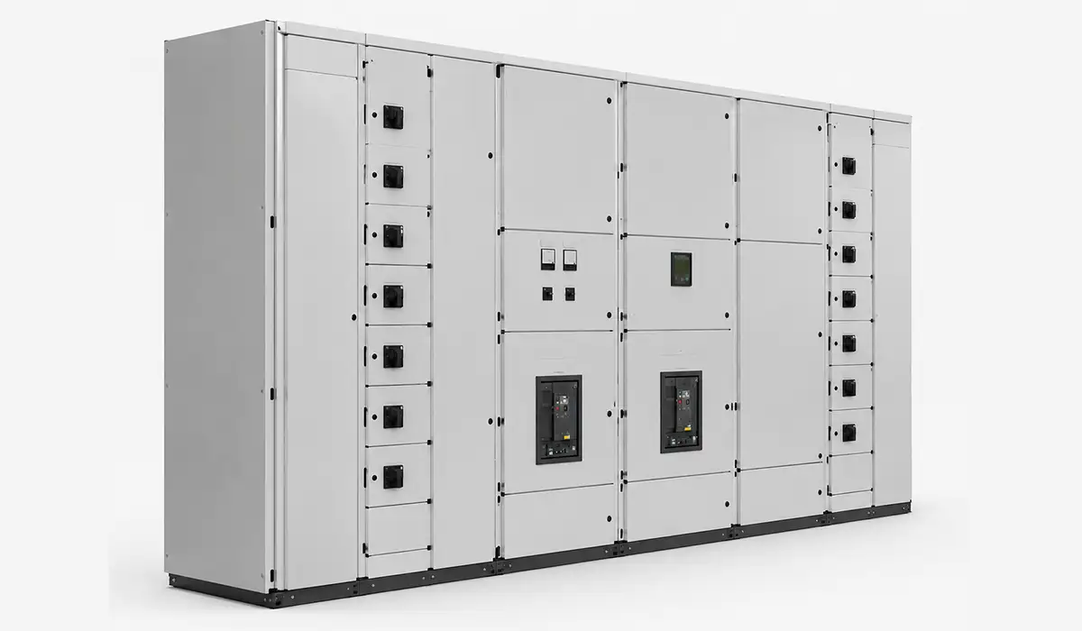
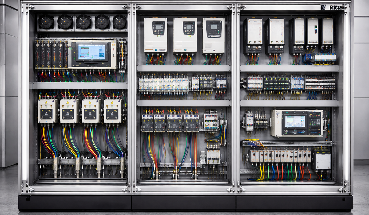
Electrical switchgear components and functions sit inside an assembly of switching devices, protective devices, measuring instruments, control equipment, and associated interconnections housed in one enclosure or coordinated set of compartments.
In IEC practice, low-voltage assemblies are governed by IEC 61439, while high-voltage switchgear above 1 kV falls under the IEC 62271 family. Those split changes design rules, tests, insulation levels, and interrupting duties.
What does not change is the purpose: receive power, connect and disconnect circuits, detect abnormal conditions, isolate faults, and protect people and equipment during operation or maintenance.
That is why similar functional blocks appear in LV switchboards, MV metal-enclosed lineups, and HV bays, even when the media, clearances, and mechanical layouts differ sharply.For a broader introduction to switchgear panel basics, that resource covers the fundamentals well.
impact of Voltage Levels in Switchgear Components : LV, MV, and HV
The voltage class is the first thing that shapes how a switchgear assembly is built. It changes the insulation, clearances, interlocking, and the governing standard, even though the underlying functions stay the same. A low-voltage assembly inside a commercial building, for example, normally points to circuit breakers, busbars, meters, and outgoing feeders inside an IEC 61439 enclosure, while medium- and high-voltage systems add specialised insulation, arc containment, and feeder protection.
For a comprehensive understanding of All Types of Electrical Panels, we highly recommend reviewing this article.
| Voltage Level | Typical Range | Common Application | Governing Standard |
|---|---|---|---|
| Low Voltage (LV) | Up to 1,000 V AC | Building distribution, MCCs | IEC 61439 |
| Medium Voltage (MV) | 1 kV – 52 kV | Industrial plants, substations | IEC 62271-200 |
| High Voltage (HV) | Above 52 kV | Transmission substations, grid systems | IEC 62271-100 |
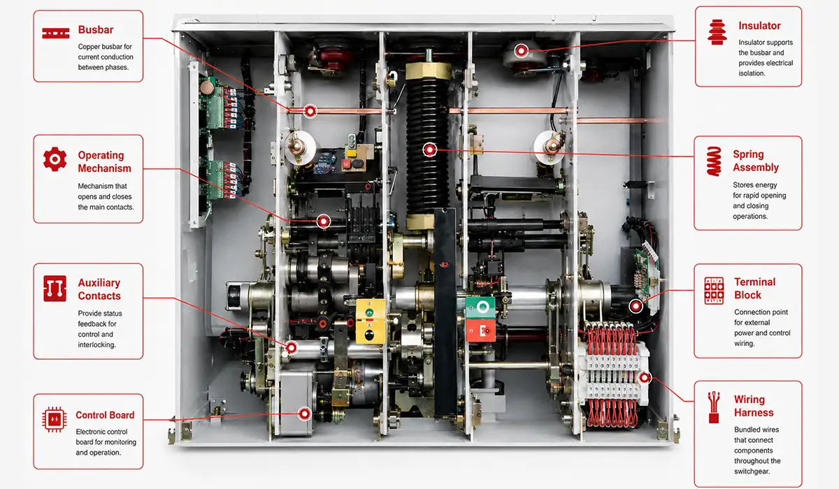
Overview of electrical switchgear definition components
A practical way to read electrical switchgear components and functions is by category rather than by voltage class. That approach makes the switchgear components list and functions easier to follow during design reviews, maintenance planning, and fault diagnosis.
Each category below answers one operational question: what switches power, what detects faults, what measures system values, what distributes current internally, what makes maintenance safe, and what supports control or monitoring.
A detailed reference is available to download. Access the IEC 62271-200:2021 reference document.
| Component Category | Function | Examples |
|---|---|---|
| Switching devices | Make and break electrical circuits | Circuit breaker, isolator, load switch |
| Protective devices | Detect and respond to abnormal conditions | Protection relay, fuse, surge arrester |
| Measuring and metering | Monitor system quantities | Current transformer, voltage transformer, energy meter |
| Busbar system | Distribute power within the switchgear | Main busbar, section busbar, earth busbar |
| Earthing and safety | Provide safe working conditions | Earthing switch, earth bar, interlocks |
| Control and auxiliary | Operate and monitor the switchgear | Control wiring, auxiliary contacts, indicator lamps |
| Enclosure and structure | House and protect all components | Panel enclosure, cable termination chamber, arc vent |
The detailed sections below follow that same map, so each part can be understood in relation to the job it performs inside the complete switchgear assembly.
Circuit Breaker — Primary Switching and Protection Device
The circuit breaker is the most critical active device in the main components of electrical switchgear. It must switch normal load current and also interrupt fault current automatically when protection commands a trip. Engineers working on modern switchgear evolution will recognize how significantly breaker technology has advanced in recent decades.
Its key ratings are rated voltage, rated current, short-circuit breaking capacity, and short-time withstand current. Those values determine whether the device can carry, survive, and clear electrical stress without losing coordination with the rest of the panel.
Circuit Breaker Types
| Circuit Breaker Type | Typical Range | Primary Application |
|---|---|---|
| ACB | LV, up to about 6300 A | Main incomers, bus couplers, large feeders |
| MCCB | LV, up to about 1600 A | Feeders, sub-main distribution, motor circuits |
| MCB | LV, up to about 125 A | Final circuits and small outgoing ways |
| VCB | MV, commonly up to 36 kV | Distribution switchgear and feeder protection |
| SF₆ breaker | MV/HV, application-dependent | GIS and compact insulated switchgear |
In practice, ACBs dominate LV incomers, MCCBs cover many feeder duties, MCBs protect smaller circuits, vacuum circuit breakers dominate MV distribution, and SF₆ technology has long been used in compact MV/HV and GIS designs, even as SF₆-free alternatives expand. For a closer look at GE breaker options, that reference provides useful product-level detail.
The full guide covers everything in one place.
Switching and Protective Devices Compared
A circuit breaker is not the only device that opens and closes a circuit, and the differences matter when specifying a panel. Disconnectors handle isolation only, load break switches and contactors handle routine switching, and fuses provide a single-operation backup against overcurrent.
| Device | Breaks Load Current | Breaks Fault Current | Operation Frequency | Typical Application |
|---|---|---|---|---|
| Circuit breaker | Yes | Yes | Occasional | Protection and isolation |
| Disconnector / isolator | No | No | Infrequent | Safe isolation only |
| Load break switch | Yes | No | Moderate | MV distribution switching |
| Contactor | Yes | No | Frequent | Motor and load control |
| Fuse | No, passive | Yes, once | Single operation | Overcurrent protection |
Trip Units and Protection Functions Within Circuit Breakers
Modern LV breakers often include thermal-magnetic or electronic trip units, so protection is built into the breaker instead of being delegated to a separate relay. Typical functions are long-time overload, short-time short-circuit, instantaneous trip, and ground-fault protection where provided.
Advanced ACBs may also use zone selective interlocking, which reduces clearing time for downstream faults while preserving selectivity with upstream devices. In LV design, that built-in logic performs the protective role that separate relays often handle in MV switchgear. This is part of a wider principle called selectivity, or protection coordination: a downstream breaker should clear a branch fault before an upstream breaker disconnects the whole switchboard. Understanding switchgear performance optimization helps engineers get the most from these protection features.
You can keep a copy for reference. Download the IEC 60947-2:2024 (PDF).
Isolator (Disconnector) — Safe Isolation for Maintenance
An isolator, also called a disconnector, is not a breaker. Its job is safe isolation, not fault interruption, which is the core difference between isolator and circuit breaker in switchgear.
It provides a visible open gap or a clearly verifiable isolated position so maintenance staff can confirm that the circuit is no longer electrically connected to the source.
Because it is not designed to interrupt load current, it must not be opened under load. That operating boundary is usually enforced by a switchgear interlock system function tied to the associated breaker.
In MV lineups, disconnectors are often distinct devices. In draw out LV designs, the isolation function is frequently achieved by racking the breaker to a test or isolated position. Those building or specifying electrical panel systems should factor isolation requirements into the panel layout from the outset.
A detailed reference is available to download. Access the IEC 62271-102:2018 reference document.
Busbar System — Power Distribution Backbone
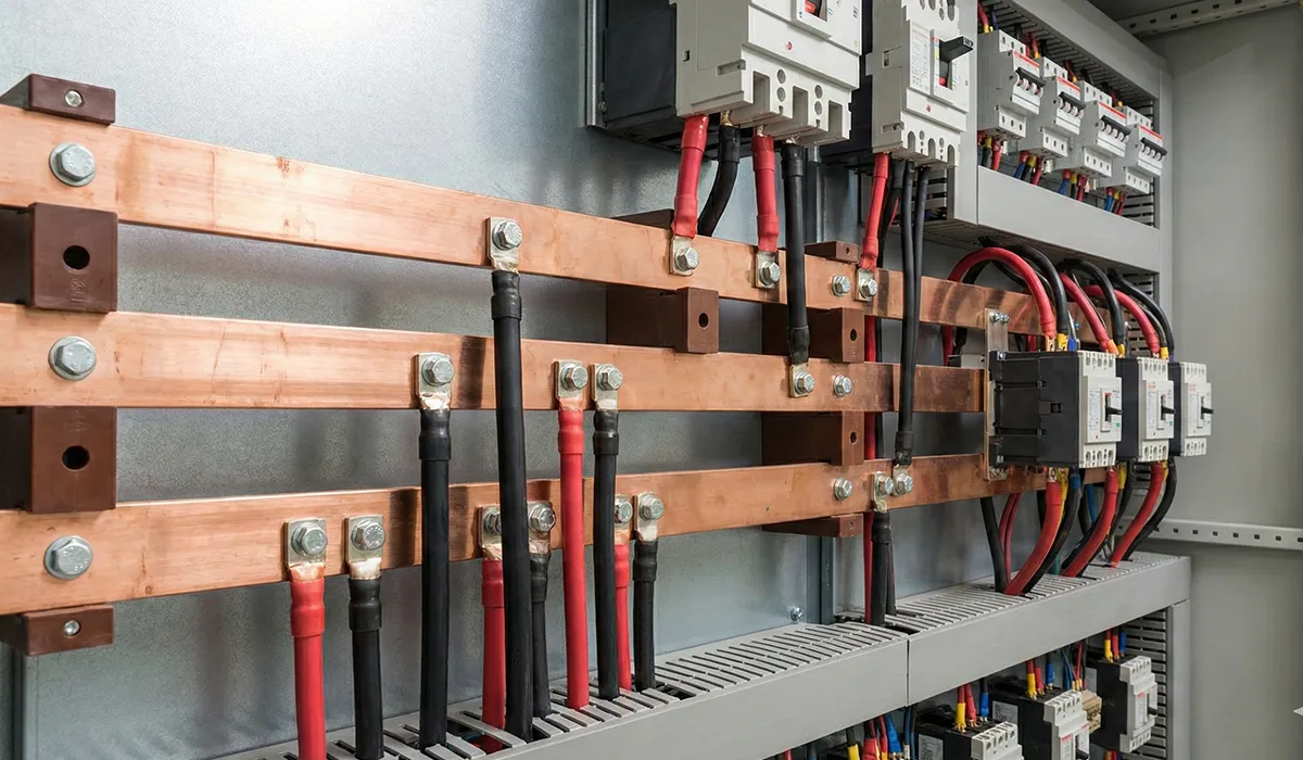
The busbar system is the electrical backbone of the switchgear cubicle. It carries incoming power, transfers it across the assembly, and distributes it to feeders, sections, and outgoing protective devices. A thorough explanation of busbar system roles in modern installations covers the design considerations in detail.
A complete assembly usually includes main phase busbars, a neutral busbar where required, and a protective earth bar. In TN-S practice, neutral and PE remain separate, which matters for fault-current return paths and bonding integrity. Designers also choose between single, duplicate, or sectioned busbar arrangements with bus couplers when system uptime is a priority.
Copper and aluminum are the main material choices. Copper offers compactness and mechanical robustness, while aluminum can reduce cost and weight; both still depend on correct temperature-rise design, support spacing, insulation, and phase-to-phase and phase-to-earth clearances.
Current Transformers (CTs) — Metering and Protection Measurement
A current transformer steps primary current down to a standardized secondary value, commonly 1 A or 5 A, so relays and meters can work safely without being exposed to the full system current. That is the essential function of current transformer in switchgear panel design.
Metering CTs prioritize accuracy around normal load and commonly use classes such as 0.2S, 0.5S, or 1. Protection CTs use classes such as 5P or 10P and are selected to stay dependable deeper into fault current.
This metering-versus-protection split is critical. A metering CT may saturate earlier to protect instruments, while a protection CT must preserve a usable fault-current image long enough for relay protection switchgear operation.
The secondary must never be left open while the primary is energized. An open CT circuit can generate hazardous voltage and damage insulation, terminals, or connected devices.
The entire resource is available in one file. Download the full Special current transformers document.
Voltage Transformers (VTs) — Voltage Measurement and Protection
Voltage transformers step system voltage down to standardized secondary values, commonly 100 V or 110 V, for meters, relays, synchronizing circuits, and other switchgear instrument panel meters. Metering windings emphasize normal-voltage accuracy, while protection windings are chosen for dependable behavior during disturbed conditions.
Inductive VTs are common in distribution switchgear, while capacitive voltage transformers are used at higher transmission voltages. Lightly loaded inductive VT circuits can face ferro resonance risk, so damping and circuit design matter.
Everything is laid out in the source file. Access the Instrument Transformers Application Guide document.
Protection Relays — Fault Detection and Switchgear Tripping
Protection relays are the decision layer of the switchgear assembly. They watch CT and VT signals continuously, compare them with settings and logic, and issue trip commands when system conditions move outside acceptable limits.
The technology has progressed from electromechanical to static to numerical relays. Modern numerical units combine multiple functions, event logs, fault records, metering, monitoring, and communications in one device instead of spreading those tasks across separate hardware. This shift is part of a broader story explored in the article on switchgear power principles.
For figures we could not fit here, GE VERNOVA‘s research on Multilin UR Family remains the definitive source to consult.
Protection Functions (ANSI)
| Protection Function | ANSI Device Number | Typical Application |
|---|---|---|
| Overcurrent protection | 50 / 51 | Phase fault detection |
| Earth fault protection | 50N / 51N | Earth fault detection |
| Differential protection | 87 | Transformer, busbar, motor protection |
| Under/overvoltage protection | 27 / 59 | Voltage-sensitive equipment |
| Under/over frequency protection | 81U / 81O | Generator and grid protection |
| Distance protection | 21 | Transmission line protection |
| Reverse power protection | 32 | Generator protection |
| Thermal overload protection | 49 | Motor and transformer protection |
ANSI device numbers remain the industry shorthand for relay functions, especially in North American practice, and they make relay schedules far easier to read across projects, test sheets, and single-line diagrams.
Earthing Switch — Personnel Safety During Maintenance
The earthing switch is a safety device, not a routine operating switch. Its role is to connect isolated conductors to earth before personnel enter the compartment or touch connected equipment.
That action removes residual charge and reduces the risk created by capacitive coupling, induced voltage, or accidental re-energization from an upstream source. It is central to earthing switch switchgear safety practice in MV and HV panels.
A standard earthing switch is intended for a dead circuit. A fault-making earthing switch is different: it is designed to close onto a live circuit and withstand the resulting short-circuit stress.
Interlocking is mandatory in principle: the earthing switch must not close until the circuit is open, and the circuit must not be re-energized while the earthing switch remains closed.
For a comprehensive understanding of Types of Earthing Systems, we highly recommend reviewing this article.
Surge Arresters — Overvoltage Protection
Surge arresters protect insulation against transient overvoltage from lightning, switching events, and some network disturbances. Their job is not continuous current carrying but rapid clamping when voltage rises beyond acceptable limits. Networks with significant harmonic content face additional stress, and the harmonic filter guide addresses how filtering relates to overall power quality protection.
Modern AC arresters use metal-oxide varistor elements. At normal service voltage they conduct negligibly; during a surge they switch into a conductive state fast enough to limit the peak seen by the protected equipment.
In switchgear, arresters are commonly placed at transformer interfaces, MV incomers, and sensitive motor or drive circuits. Surge arrester switchgear overvoltage coordination depends on protection level, energy duty, and insulation strength across the connected equipment.
Further exploration of Pollution degree and overvoltage can be found in the following recommended reading.
Switchgear Enclosure and Arc Flash Management
The enclosure is not just sheet metal. It establishes segregation, supports internal clearances, protects components from the environment, and forms the barrier that controls exposure during normal operation or internal failure. Engineers specifying enclosure systems often reference Rittal panel solutions as a benchmark for cabinet quality and thermal management.
Its switchgear enclosure IP rating describes resistance to ingress of solids and liquids under the IEC IP system. Internal arc classification addresses a different risk: whether the assembly can contain the effects of an internal arc without endangering nearby people.
IEC internal arc designations also indicate accessibility. Schneider’s IEC 62271-200 guidance, for example, explains that type A is for authorized personnel, while public-access applications are treated more severely; hot-gas ducts, pressure flaps, and arc vents are used to steer energy away from access zones.
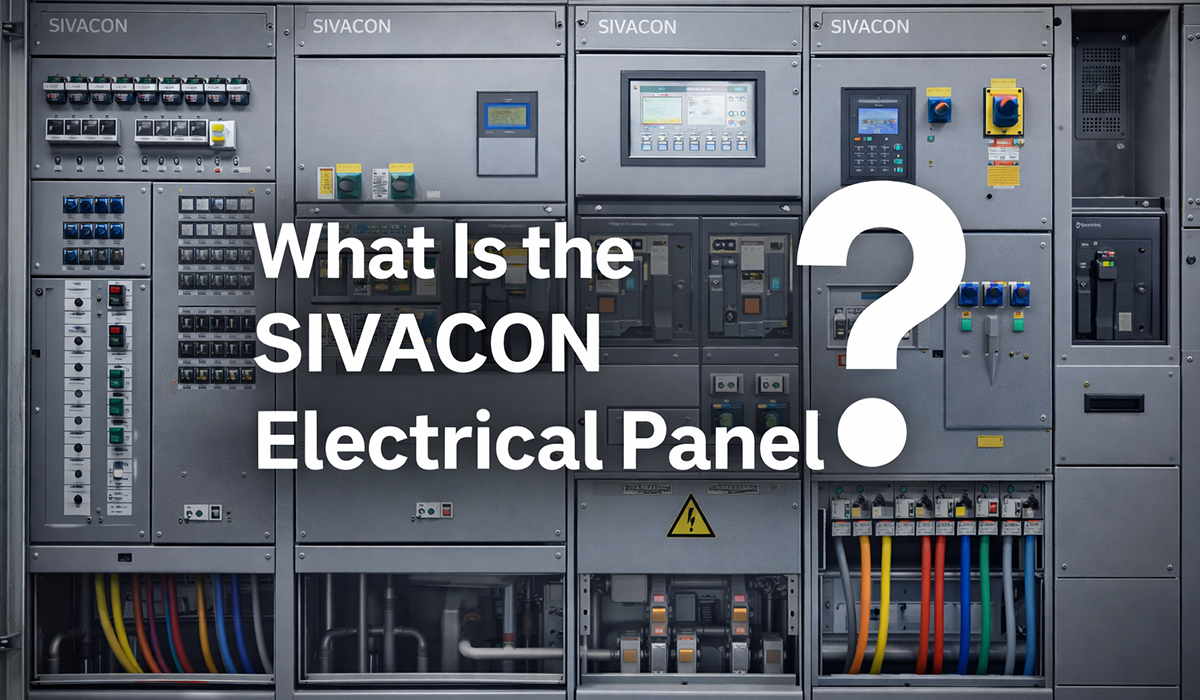
The Sivacon panel overview is another reference that illustrates how enclosure design and arc protection are integrated in practice.
How the Switchgear Types Compare
The components covered above appear inside several different switchgear formats, and the choice of format mainly affects insulation medium, footprint, and accessibility rather than the underlying functions.
| Switchgear Type | Insulation Medium | Voltage Level | Key Distinguishing Feature |
|---|---|---|---|
| Air-Insulated Switchgear (AIS) | Air | LV and MV | Larger footprint, accessible busbars |
| Gas-Insulated Switchgear (GIS) | SF6 or clean air | MV and HV | Compact, sealed, climate-independent |
| Vacuum Switchgear | Vacuum interrupter | MV | Low-maintenance interruption |
| Metal-Clad Switchgear | Air | MV | Drawout breakers, compartmentalised design |
| Metal-Enclosed Switchgear | Air | LV and MV | Fixed units, lower cost |
| Motor Control Centre (MCC) | Air | LV | Motor starter and feeder modules |
The main practical difference is between AIS and GIS: AIS uses air and needs more clearance, while GIS uses sealed gas or clean-air insulation to reduce footprint, which is why it is favoured for compact MV/HV substations.
Control Wiring, Auxiliary Contacts, and Indication
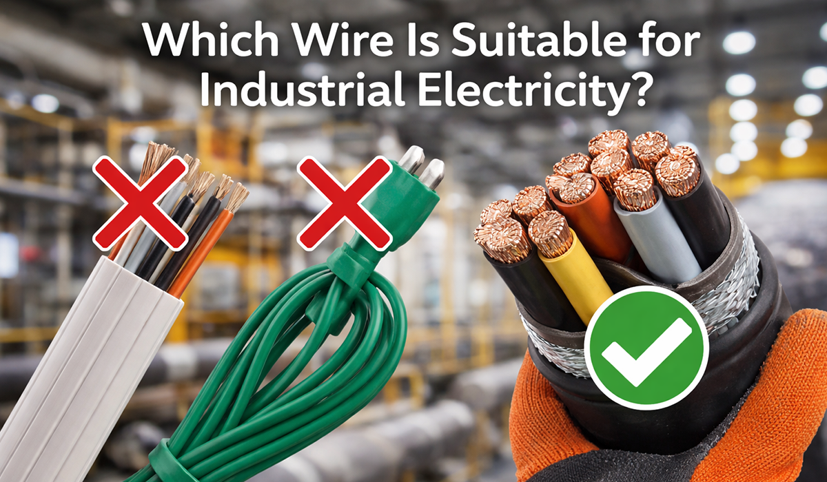
Control wiring is the low-energy nervous system of the panel. It carries close commands, trip commands, alarms, permissive, interlocks, and status signals between relays, breakers, meters, operator devices, and remote systems. Selecting the right industrial wire for these circuits is a practical decision that directly affects long-term reliability and compliance.
Those circuits often use 24 V DC, 48 V DC, or 110–240 V AC control supplies depending on the application, reliability philosophy, and legacy site practice. The switchgear control wiring function is coordination, not power distribution.
Auxiliary contacts provide position and event feedback. Manufacturer guidance for breaker auxiliaries explicitly uses them to report open, closed, or tripped states remotely, which makes them essential for interlocks, mimic diagrams, and SCADA points.
Indication devices then turn those signals into operator visibility through meters, lamps, fault flags, and HMIs, while cable termination components and chambers provide the practical interface between internal assemblies and field cabling.
For a closer look at this topic, see Schnider Electric‘s guide to Characteristics of PowerPact, which examines the issue in greater depth.
What are the best suppliers of low-voltage electrical switchgear components?
-
- Schneider Electric — Usually one of the first names panel builders think of, and for good reason. The range covers circuit breakers, protection devices, distribution systems, and control products — and the documentation is thorough enough that most engineers can find what they need without chasing a local rep. If global availability and spare-part access matter on your project, Schneider is a safe place to start.
- Siemens — Tends to show up most on industrial projects — factories, infrastructure, and larger distribution systems where the switchgear has to talk to automation or monitoring equipment. The integration story is where Siemens usually pulls ahead of the competition.
- ABB — The name that comes up when the conversation shifts from budget to performance. Low-voltage breakers, contactors, protection devices, motor control, switchgear for demanding environments — the catalogue is wide, and the products hold up in applications where failure is not an acceptable outcome.
- Eaton — A strong choice for commercial buildings, data centers, and anything where protection coordination is a priority. Its components are well-suited to systems where reliability has to be engineered in from the start, not patched in later.
- Legrand — Does not always get the same attention as the bigger names, but for building distribution, modular protection, enclosures, and busbar trunking, it is genuinely hard to beat. Commercial and residential projects where panel finish and installation quality matter tend to lean on Legrand heavily.
- LS Electric — Worth a serious look when the project has a defined budget and cannot absorb the premium of the European majors. ACBs, MCCBs, contactors, relays, motor control — the product line is complete, and in markets where competitive pricing drives specification decisions, LS Electric shows up regularly.
- Mitsubishi Electric — The natural choice for machine builders and OEM panels. The low-voltage breakers and contactors are well-matched to manufacturing environments, and the performance is consistent enough that production engineers tend to stick with them once they have used them on a few lines.
- Fuji Electric — Compact, reliable low-voltage protection and control components that work well in machinery panels and production lines. Another Japanese supplier that earns its place on project shortlists without making a lot of noise about it.
- Rittal — A different conversation entirely. The brand is about the enclosure side of the build — cabinets, cooling, panel accessories, and the mechanical structure that holds everything else together. If the project demands a clean, well-engineered cabinet, Rittal is one of the few names worth specifying by brand.
- Phoenix Contact and Weidmüller — Rarely appear on a panel nameplate, but they have a larger effect on the finished product than most people credit. Terminal blocks, relays, connectors, marking systems, DIN-rail accessories — the wiring quality and long-term maintainability of a panel often comes down to how well these components were specified.
In practice, the right supplier depends entirely on what the project actually requires. For premium low-voltage switchgear, Schneider, Siemens, ABB, and Eaton are where most serious specifications start. For building distribution, Legrand is the common answer. When the budget is tighter and the application is industrial, LS Electric, Mitsubishi, and Fuji give up less than you might expect.
Brand name alone should never close the decision. The supplier has to match the voltage level, short-circuit rating, breaking capacity, local standards, certification requirements, spare-part availability in the region, and the overall design of the switchgear system. Get those criteria right first, and the shortlist usually writes itself.
Conclusion about electrical switchgear components
Understanding electrical switchgear components and functions is fundamental to specifying, operating, and maintaining safe power distribution systems. Although LV, MV, and HV assemblies differ in construction, they rely on the same core functional elements: circuit breakers for switching and fault interruption, isolators for safe maintenance isolation, busbars for current distribution, CTs and VTs for measurement, protection relays for decision-making, earthing switches for personnel safety, surge arresters for overvoltage control, and enclosure systems for environmental and arc-fault protection. For those managing industrial control systems, these components interact directly with automation and monitoring layers that depend on switchgear reliability.
For engineers and facility operators, the value is practical: each component affects system reliability, fault performance, maintenance safety, and long-term serviceability. A well-designed switchgear assembly is not just a collection of parts, but a coordinated system in which every device must match the electrical duty, protection philosophy, and operating environment. When these components are selected and integrated correctly, switchgear delivers the control, protection, and resilience that modern industrial and commercial power systems depend on. Readers who want to go deeper into the subject of underground conduit systems will find that infrastructure topic closely connected to how switchgear assemblies are fed and routed in complex installations.


Rate this article
Choose a rating from 1 to 5 stars.
No ratings yet