






What Is a Harmonic Filter?
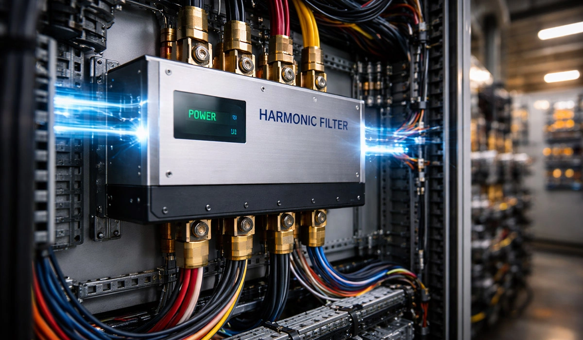
A harmonic filter is a device that reduces the harmonic currents flowing in a power network, or prevents them from reaching equipment that can’t tolerate them. In low-voltage power factor correction it almost always means a reactor connected in series with a capacitor, sized so the pair resonates at a frequency deliberately placed below the lowest significant harmonic.
That series pair does two things at once. It shifts the network’s resonance point away from any harmonic frequency, and it presents an inductive impedance at harmonic frequencies, so harmonic current is diverted away from the capacitor rather than amplified into it.
The distinction that matters commercially: a capacitor bank corrects power factor. A detuned capacitor bank corrects power factor and survives a harmonic-rich network. The reactor is what separates the two.
What Does a Harmonic Filter Do? Four Purposes
- Prevents resonance. A capacitor and the network’s inductance form a parallel resonant circuit. If that resonance lands near a harmonic present in the network, harmonic current is amplified — sometimes by an order of magnitude. The reactor moves the resonance to a frequency where nothing lives.
- Limits harmonic current into the capacitor. Capacitor impedance falls as frequency rises, so an unprotected capacitor is the lowest-impedance path for every harmonic in the system. The series reactor reverses that.
- Protects against overheating and overcurrent. Harmonic current raises RMS current and dielectric losses. Capacitor failure rates rise roughly 15% for every 5 °C above the rated ambient.
- Improves power quality at the point of common coupling. Lower distortion at the PCC is what utilities and standards such as IEEE 519 actually measure against.
Where Harmonics Come From
Harmonics are extra currents or voltages in the power network that can reduce power quality and affect sensitive equipment.
In industrial low-voltage networks, especially when variable speed drives (VSDs/VFDs) on induction motors are installed, harmonics are generated significantly and, if left uncontrolled, can cause equipment heating, shorter capacitor life, and disruption in capacitor bank operation.
But harmonics are not limited to industrial environments. In residential and commercial buildings, many devices such as TVs, computers, and energy-saving lamps also generate harmonics. If these abnormal currents are not controlled,
they may cause voltage fluctuations, malfunctions in electronic equipment, and reduced network efficiency. To manage this issue, using a capacitor harmonic filter or a capacitor bank harmonic filter is a practical approach. These filters reduce and control harmonic currents, prevent capacitor overheating, and improve network power quality.
So even in small residential and commercial buildings, correct harmonic filter installation can noticeably improve electronic equipment performance and extend the electrical system’s service life.
Which Harmonics Matter Most in LV Networks
In theory, many harmonics can exist in a network, but in low-voltage networks, the 3rd and 5th harmonics have the
greatest practical importance. The 3rd harmonic is more common in office and commercial buildings and tends to
accumulate in the neutral conductor, while the 5th harmonic is the most common harmonic in industrial environments
and plays the biggest role in creating resonance with capacitor banks.
| Order | 50 Hz | 60 Hz | Where it dominates | Behaviour |
|---|---|---|---|---|
| 3rd | 150 Hz | 180 Hz | Offices, commercial, single-phase SMPS, LED lighting | Triplen — sums in the neutral, can exceed phase current |
| 5th | 250 Hz | 300 Hz | Industrial, 6-pulse drives and rectifiers | Negative sequence — main resonance risk with capacitor banks |
| 7th | 350 Hz | 420 Hz | Industrial, same sources as 5th | Positive sequence, lower magnitude |
| 11th / 13th | 550 / 650 Hz | 660 / 780 Hz | Heavy 6-pulse and 12-pulse converters | Usually addressed by the detuned bank’s high-frequency behaviour |
Note that everything on this page assumes a 50 Hz network unless stated. At 60 Hz the tuning frequencies shift: a 7% reactor resonates at 227 Hz rather than 189 Hz.
(That last line matters — the page is entirely 50 Hz-framed while receiving US traffic.)
The Role of a Capacitor Harmonic Filter
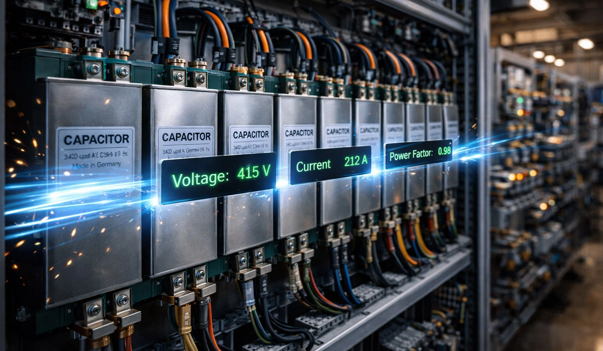
- When tuned to a specific frequency (such as 7% or 14%), it prevents harmonic resonance.
- Protects capacitors and increases equipment stability and service life.
- Correct kVAR selection and filter tuning percentage are critical for safe operation.
Types of Harmonic Filters: Passive, Active and Hybrid
To control harmonics in low-voltage and industrial networks, two main categories of harmonic filters are used: passive filters and active filters. The filter type selection depends directly on harmonic levels, load type, and the capacitor bank structure.
Passive Harmonic Filters
Passive filters are the most common and cost-effective method for harmonic control in industrial networks. These filters
are made from a combination of a capacitor and a reactor, and they are tuned to a specific frequency.
- Detuned Filter (Detuned Filter)
In this type, the resonance frequency of the capacitor–reactor set is intentionally adjusted below the dominant
harmonic (usually the 5th harmonic), such as 7% tuning (189 Hz) or 14% tuning (134 Hz).
Its main application is preventing resonance and protecting the capacitor bank in networks with moderate THD. - Tuned Filter (Tuned Filter)
This filter is tuned exactly to the frequency of a specific harmonic (for example, the 5th or 7th harmonic) and
directly absorbs that harmonic.
It is mostly used in industrial networks with heavy loads and high harmonics.
Active Harmonic Filter
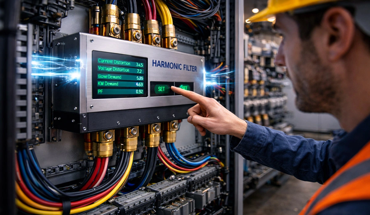
An active filter is an electronic device that measures harmonics in real time, injects an inverse current, and eliminates
distortion.
These filters are used for:
- Variable and unpredictable loads
- Networks with multiple harmonic orders simultaneously
- Sensitive projects (data centers, hospitals, precision production lines)
However, high cost and maintenance complexity usually make them a complement to passive filters, not a complete replacement.
Dynamic and Hybrid Harmonic Filters
“Dynamic harmonic filter” is used two ways in the market, and it’s worth separating them.
Dynamic = fast-responding active filter. An active unit that samples the load current and injects a cancelling current within a fraction of a cycle. The value is on loads whose harmonic spectrum changes constantly — welding plant, lifts and cranes, arc furnaces, variable production lines — where a passive filter tuned to yesterday’s spectrum is useless today.
Dynamic = hybrid passive + active. A detuned passive bank handles the bulk of the reactive power and the dominant harmonic cheaply; a smaller active unit sits alongside it to handle the residual and the variable orders. This is usually the economic answer on large industrial sites, because active filters are priced by harmonic current capacity and the passive stage removes most of it before the active unit sees it.
Related but distinct: dynamic power factor correction means thyristor-switched capacitor stages that respond in milliseconds instead of contactor-switched stages that take seconds. It addresses switching speed, not harmonics — though the two are often specified together, and thyristor switching avoids the inrush that shortens contactor and capacitor life.
Detuning Factors Explained: 5.67%, 7% and 14%
The detuning factor p is the reactor’s reactance as a percentage of the capacitor’s reactance. It sets the series resonance frequency:
f_r = f₁ / √p
| p | fr at 50 Hz | fr at 60 Hz | Use when |
|---|---|---|---|
| 5.67% | 210 Hz | 252 Hz | 5th dominant, and you want the bank to absorb more 5th harmonic current |
| 7% | 189 Hz | 227 Hz | The default. 5th harmonic dominant, industrial networks with drives |
| 14% | 134 Hz | 161 Hz | 3rd harmonic present — single-phase SMPS, UPS, commercial buildings, or where a generator supplies the site |
Two rules that decide the choice:
The tuning frequency must sit below the lowest significant harmonic, with margin. IEEE 519-2022 guidance is at least 10% separation between the tuning frequency and any significant harmonic order. Tune too close and the bank amplifies rather than attenuates.
Check for ripple control signals. Utilities in many markets inject audio-frequency control signals onto the network, commonly 175–1350 Hz. A detuned bank tuned near the ripple frequency will absorb the signal and can disable the utility’s remote metering or load control. Confirm the ripple frequency with the DNO before selecting p.
Capacitor Voltage Rating: The Step Most Specifications Miss
The reactor is in series with the capacitor, so at fundamental frequency it drops voltage — and the capacitor sees more than nominal system voltage:
V_c = V_sys / (1 − p)
| System voltage | Detuning | Capacitor sees | Rating to specify |
|---|---|---|---|
| 400 V | 7% | 430 V | 480 V minimum, 525 V typical |
| 400 V | 14% | 465 V | 525 V |
| 480 V | 5.67% | 509 V | ≥ 530 V |
| 480 V | 7% | 516 V | 525–550 V |
Then add grid tolerance. A 400 V network is permitted ±10%, so the long-term upper operating limit is 440 V — which pushes the 7% case to roughly 473 V before harmonic voltage superposition is even considered.
What goes wrong when this is skipped: a standard 440 V or 450 V capacitor fitted behind a 7% reactor runs permanently at borderline overvoltage. The metallised film self-heals repeatedly, capacitance falls, and the unit fails years early — with no fault indication and nothing obviously wrong at the switchgear. It is the most common failure mode in detuned banks and it is a purchasing error, not an operational one.
Always specify the capacitor voltage rating and the detuning factor together. A quotation that names one without the other is incomplete.
Key Points in Capacitor Bank Design to Reduce Resonance
Resonance is one of the most dangerous phenomena in networks with capacitor banks. It occurs when a harmonic frequency matches
the network’s resonance frequency. To prevent it, the following points are essential:
- Checking THD percentage of current and voltage before designing the capacitor bank
- Correct selection of capacitor reactive power (kVAR) according to the network’s real load
- Using a detuned harmonic filter in the presence of dominant 5th or 3rd harmonics
- Coordinating the filter tuning frequency with the network structure (for example, 7% or 14%)
- Reactor and capacitor quality in terms of harmonic current capability and operating temperature
In proper design, the goal is not only power factor correction, but also network stability, longer equipment life, and preventing
hidden harmonic damage.
THD, THDi and TDD: Which Number Actually Decides Your Filter
THD (Total Harmonic Distortion) is an index that measures the harmonic “pollution” of a power network and shows what percentage of
the network’s current or voltage deviates from the standard sinusoidal waveform. The higher the THD, the more non-linear loads such
as inverters, motor speed drives, UPS, and power electronics equipment are present in the network.
In practice, current THD (THDi) is the most important parameter for selecting a capacitor harmonic filter and designing a capacitor bank,
because it directly affects capacitor current and resonance probability.
THD vs TDD — and why the difference costs money
THD measures distortion relative to the fundamental at the moment of measurement. TDD (Total Demand Distortion) measures harmonic current relative to the installation’s maximum demand load current. IEEE 519 sets its current limits in TDD, not THD, and the reason is practical: on a lightly loaded feeder, THDi can read 35–40% while the absolute harmonic current is negligible. Specifying a filter against that number buys capacity you don’t need.
Rule of thumb: if you are quoting a distortion figure to a supplier, state the measured current, the load at the time, and the maximum demand, not just a percentage.
When a detuned filter is justified
(Replace the invented bands with sourced guidance:)
| Condition | Typical recommendation |
|---|---|
| THD-U below 3% | Standard capacitor bank usually acceptable |
| THD-U above 3% | Manufacturers commonly recommend detuned reactors from this point |
| THDi 10–20%, 5th dominant | 7% detuning (189 Hz) |
| THDi above 20%, or 3rd harmonic present | 14% detuning (134 Hz) |
| Qc / Ssc above 0.05 | Detuning required regardless of measured THD |
| Variable or unpredictable spectrum | Active or hybrid filter |
The Qc/S_sc row is the one engineers use and homeowners never see: if the capacitor bank’s reactive power exceeds about 5% of the short-circuit power at the connection point, resonance is likely no matter what today’s THD reading says.
Governing standards: IEEE 519-2022 for harmonic limits at the PCC; IEC 61000-2-4 for compatibility levels in industrial installations; EN 50160 for public supply voltage characteristics; IEC 61000-3-2 and 3-12 for equipment emission limits.
Interpreting THD Percentage for Harmonic Filter Selection
- THD below 10%
The network is relatively healthy, and usually a simple capacitor bank without a special filter can be used, although using a detuned
filter is safer. - THD between 10% and 20%
This is the most common range in factories and buildings with drives and electronic equipment. In this condition, using a 7% detuned
capacitor harmonic filter (189 Hz) is recommended to prevent resonance and capacitor overcurrent. - THD above 20%
The network is heavily polluted with harmonics. In this situation, 14% filters (134 Hz) or a combination of passive and active filters
usually becomes necessary to protect the capacitor bank and equipment.
The Relationship Between THD and Choosing a Capacitor Bank Harmonic Filter
Ignoring THD is one of the most common reasons for early capacitor bank failure. If THD is not checked, the filter may be selected correctly
in terms of nominal rating, but in real operation it can be exposed to harmonic currents, leading to higher temperature, overcurrent, and
frequency resonance.
Correct Selection of Capacitor Reactive Power (kVAR) for the Network
To choose the correct capacitor rating, three main factors must be considered:
1) Real network load (required reactive power)
- Before purchase, determine the required reactive power by measurement or technical consultation.
- Choosing a capacitor below the requirement causes incomplete compensation; choosing a capacitor too large causes overcurrent and equipment damage.
2) Harmonic filter percentage (7% or 14%)
- 7% is suitable for networks with THDi between 10% and 20% and a dominant 5th harmonic.
- 14% is recommended for more polluted networks and where the 3rd harmonic is dominant.
3) Power distribution in the network
- It is better to split the required power into multiple lower-capacity capacitors to achieve better flexibility and control and reduce resonance risk.
4) Reactive power derating with a reactor fitted
A capacitor’s nameplate kVAR is stated at its own rated voltage. Behind a detuned reactor, the reactive power delivered to the network is not the nameplate figure — the reactor consumes part of it, and the capacitor operates at a different voltage from its rating. Confirm the delivered kVAR at system voltage with the supplier, not the capacitor’s nameplate. Sizing to the nameplate consistently under-compensates, typically by 5–15%.
Detuned Capacitor Bank Selection Guide
positioning. Add two columns so the table carries the new content:)
| kVAR | Detuning | Capacitor rating (400 V system) | Application |
|---|---|---|---|
| 12.5 | 7% | 480 V | Small network, moderate load, THDi 10–15% |
| 20 | 7% | 480 V | Medium load, THDi ~15% |
| 25 | 7% | 480 V | Small industrial, moderate non-linear load |
| 30 | 7% | 480 V | Industrial with several drives, THDi 15–20% |
| 40 | 7% | 480–525 V | Large industrial, high non-linear load |
| 50 | 7% | 525 V | Large industrial, high-power equipment |
| 12.5 | 14% | 525 V | 3rd harmonic dominant |
| 25 | 14% | 525 V | Industrial, THDi above 20% |
| 50 | 14% | 525 V | Heavily polluted industrial network |
Note: For large networks or variable loads, splitting the power into multiple lower-capacity capacitors is recommended for better control and to avoid overcurrent and resonance.
Final Summary
Harmonics can disrupt capacitor bank operation and overall network equipment, and higher THD increases resonance risk and reduces system lifespan.
Using a capacitor harmonic filter, choosing the correct capacitor kVAR, and selecting the proper tuning percentage (7% or 14%) help control harmonic currents,
protect capacitors, and stabilize the network.
Correct filter and capacitor selection must be based on the network’s real load, the dominant harmonic, and THD percentage. By following these principles,
the network becomes safer, and optimal performance and equipment lifespan are ensured.
And specify the capacitor voltage rating alongside the detuning factor. A bank that is correctly tuned and incorrectly rated will still fail early.


Rate this article
Choose a rating from 1 to 5 stars.
No ratings yet