



If you’d rather listen than read, feel free to play the audio file below for the rest of this article.
What Is Electrical Panel Design?
It is the process of engineering a safe, reliable and compliant assembly for distributing, protecting, controlling and monitoring electrical power.
In industrial LV distribution it has to reconcile competing demands at once. Load demand sets conductor sizing; fault level sets withstand requirements; enclosure conditions constrain thermal design; and maintainability constrains layout. Each pulls against the others.
The applicable standards then set the ceiling on what can be varied, which is why compliance belongs in the design phase rather than at inspection.
Good design starts with a clear picture of what the assembly is and how it fits into the wider system. Our guide to electrical panels and switchgear covers those basics before you go deeper.
Electrical Panel vs Switchboard vs Switchgear
The terms are used loosely in specifications, and the difference matters commercially.
Electrical panel is the general term for an enclosure containing electrical devices. It carries no implication about size or rating.
Distribution board is typically a smaller branch distribution assembly, feeding final circuits.
Switchboard is a larger LV distribution assembly with incomers and outgoing feeders, dividing an incoming supply into multiple circuits.
Switchgear describes more robust equipment built around switching, protection, isolation and fault performance, usually with drawout construction and higher withstand ratings.
Distribution board design, switchboard panel design and power distribution panel design are governed by the same standard series, but sit at different points within it. Electrical switchboard design sits at the larger end.
If the terminology still feels fuzzy, start with the fundamentals. Read what an electrical panel is and how it differs from larger assemblies.
Key Design Inputs Before Starting
Design cannot begin without these. Missing any one of them means the design will be revised later, which is where schedule and margin both go.
| Input | Why it matters | Example |
|---|---|---|
| Load schedule | Sets incomer and feeder ratings | 1,250 A total connected, 0.8 demand factor |
| Voltage and frequency | Determines insulation and component selection | 400 V, 50 Hz, 3-phase 4-wire |
| Fault level | Sets breaker breaking capacity and busbar bracing | 50 kA for 1 s at the incomer |
| Earthing system | Governs neutral and protective conductor arrangement | TN-S, TN-C-S or IT |
| Cable entry | Decides gland plate position and termination space | Bottom entry, rear access |
| Installation environment | Drives enclosure and thermal design | Indoor plant room, 40 °C ambient |
| IP rating | Constrains ventilation options | IP54 to IEC 60529 |
| Future expansion | Determines spare ways and bus capacity | 20% spare feeder positions |
| Applicable standard | Sets the verification route | IEC 61439-2 |
Add the number of incomers and feeders, space limitations, and any utility or consultant specification. Those last items are where projects most often discover a constraint after the layout is fixed.
For anyone who wants to go deeper, this further reading provides a much wider view.
Once the inputs are fixed, the type of equipment follows from them. Our guide on choosing switchgear shows how to match the assembly to the load.

Step-by-Step LV Switchboard Design Process
Ten steps, in dependency order. The LV switchboard design process step by step matters because several steps cannot be revisited cheaply once the next has started.
1. Define the Load Requirements
Start from connected load, then apply demand and diversity factors to reach the design load.
Motor loads need starting current considered separately from running current. Lighting, HVAC and process loads have different duty cycles, and applying a single diversity factor across all of them understates peak demand.
Add future expansion explicitly rather than as a margin buried in the calculation, so the spare capacity is visible to whoever specifies the next extension.
2. Prepare or Review the Single-Line Diagram
The single line diagram defines the incoming source, bus sections, tie breakers, outgoing feeders, metering, protection and major loads.
Review it before designing to it. An SLD prepared by a consultant frequently assumes equipment arrangements the panel cannot physically deliver — most often bus section positions and cable entry direction.
3. Select the Incomer and Outgoing Breakers
Knowing how to select circuit breakers for an LV switchboard means matching three things: rating, breaking capacity and coordination.
ACBs suit incomers and large feeders where drawout access and adjustable protection are needed. MCCBs cover most outgoing feeders. MCBs handle final circuits, and RCDs add residual current protection where required.
Breaking capacity must exceed the available fault current at that point. Selective coordination then determines whether a downstream fault trips only the local device or takes out the incomer with it.
4. Calculate Short-Circuit Current
The fault level at the panel location drives four separate decisions: breaker interrupting capacity, busbar cross-section, busbar bracing and support spacing, and the assembly’s overall withstand rating.
It is a property of the location, not the equipment. Transformer size and impedance, conductor length and utility contribution all feed into it, which is why relocating a panel can invalidate its rating.
5. Size the Busbars
Anyone asking how to size busbars in an electrical panel is answering two questions at once: continuous rating and short-time withstand.
Continuous rating comes from ampacity tables corrected for enclosure temperature, mounting orientation and grouping. Ampacity data assumes conditions that a closed panel rarely matches, so the correction factors do real work here.
Short-time withstand is the separate one. Electrodynamic forces during a fault decide support spacing and phase spacing, and those forces scale with the square of the peak current rather than with the continuous rating.
Copper conducts at about 58 MS/m against 36 MS/m for aluminium. Whichever is chosen, bar geometry is drawing-specific — it cannot be ordered from stock, which puts it late on the critical path.
6. Select Cable Sizes and Termination Space
Cable sizing follows the feeder rating, but the panel dimension follows the cable.
Bending radius is the constraint people underestimate. A large single-core cable needs substantially more depth behind the gland plate than the lug itself suggests. Add lug space, gland plate area, segregation between power and control, and maintenance access.
Decide top or bottom entry early. Changing it later moves the busbar arrangement.
7. Choose the Enclosure and IP Rating
Indoor or outdoor installation, dust, water, heat, corrosion and access requirements together set the enclosure specification.
The IP rating is more constraining than it looks, because it eliminates cooling options. An IP54 panel can take filter fans; an IP66 panel cannot, and needs a sealed heat exchanger or air conditioner instead.
Material matters alongside the rating. IP measures dust and water only, not corrosion.
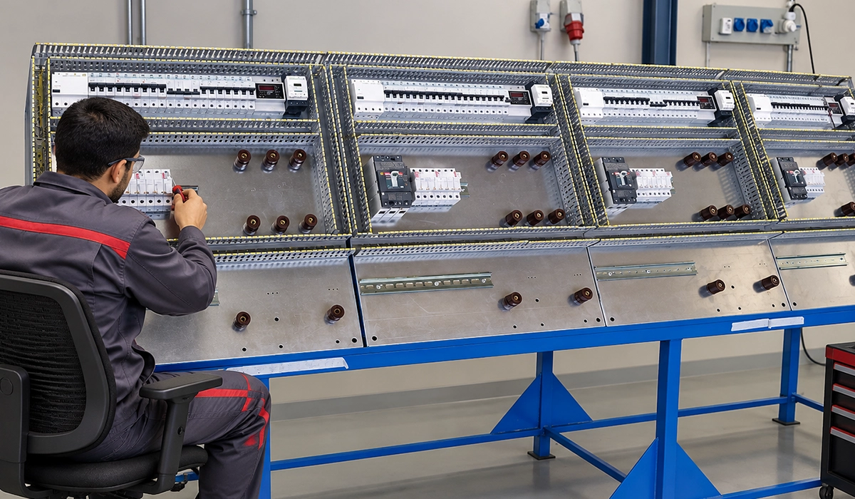
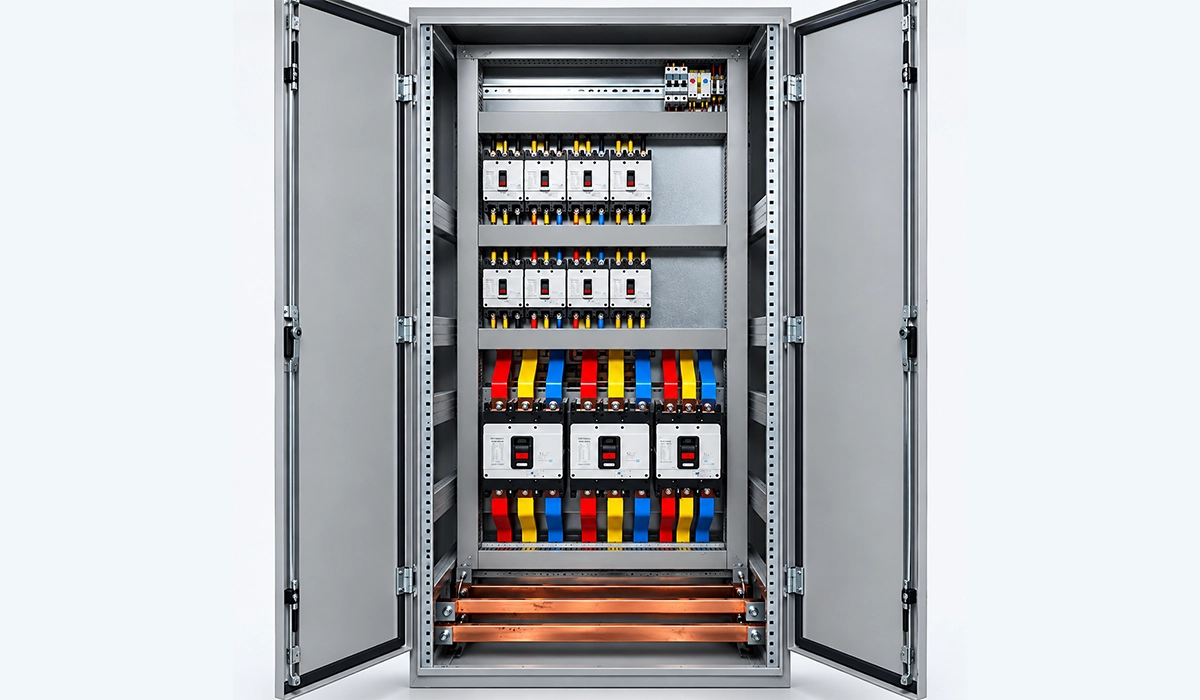
8. Plan the Internal Layout
Layout is where Form of Separation is decided. IEC 61439-2 defines Forms 1 to 4, with a and b sub-variants for Forms 2 to 4 — seven configurations in total.
Form 1 has no internal separation. Form 2 separates the busbars from the functional units. Form 3 adds separation between functional units. Form 4 separates busbars, functional units and their terminals, so work on one outgoing circuit does not expose any other.
The 4a and 4b distinction is the one specifications turn on. In Form 4a the terminals sit in the same compartment as the associated functional unit. In Form 4b each set of terminals has its own compartment. Sub-variant definitions are described inconsistently across secondary sources, so confirm the form against the project specification and the manufacturer’s verification data rather than the label alone.
9. Design Earthing and Neutral Systems
The earth bar and neutral bar are sized from the fault path, not from convenience.
Where third harmonic content is significant, the neutral carries more current than the phases, because triplen harmonics add arithmetically rather than cancelling. IEC 60364-5-52 treats 33% third harmonic as the threshold at which the neutral becomes the basis for sizing.
Protective circuit continuity is one of the verified characteristics under IEC 61439, so masked contact points and bonding straps belong in the design rather than in assembly.
10. Add Metering, Monitoring, and Control
Energy meters, multifunction meters, CTs, VTs, protection relays and communication modules all consume panel volume and generate heat.
Decide the integration route early. BMS or SCADA connectivity affects cable routing, segregation and terminal count, and adding it after layout approval usually costs a compartment.
Every one of these steps relies on well-chosen hardware. Browse our overview of switchgear components to see what goes into the assembly.
IEC 61439 and Compliance Considerations
IEC 61439-1 gives the general rules and IEC 61439-2 covers power switchgear and controlgear assemblies. The framework separates the original manufacturer, who carries out design verification, from the assembly manufacturer who builds within it.
Design verification comprises 21 individual verifications, archived for ten years. It covers temperature rise, dielectric properties, short-circuit withstand, protective circuit continuity, clearances and creepage distances, mechanical operation, and documentation and labelling. Routine verification is performed on each assembly produced.
One consequence deserves emphasis. Deviating from the original manufacturer’s instructions forces a new, full design verification rather than routine verification alone.
This is general technical guidance rather than certification advice. Confirm requirements with qualified engineers and against the applicable local code.
If you would like to explore this subject further, you can read more about it here.
Compliance depends heavily on how the assembly behaves as a whole under load. Learn more about switchgear performance and what influences it.
Electrical Panel Layout Best Practices
Ten practices that reduce revision cycles later.
Separate power and control wiring where practical. Provide sufficient cable termination space, measured from the bending radius rather than the lug. Allow room for heat dissipation, and avoid overcrowding devices — the two are the same problem.
Maintain service access to every device that will be worked on live. Use clear labelling. Plan spare feeder positions rather than filling the enclosure. Keep busbar paths logical and compact, because every additional bend is fabrication time and an additional joint.
Consider safety during operation and maintenance, and use manufacturer-approved components so that component data supports the verification.
For a clearer and more complete explanation, this page goes into far more depth than we can cover in a short text.
A logical busbar path keeps both the layout and the fabrication simple. See how busbars in electrical systems shape the way a panel is arranged.
Common Electrical Panel Design Mistakes
Twelve recurring errors, grouped by where they originate.
Electrical. Undersized busbars. Insufficient short-circuit rating. Poor breaker coordination. Using components without checking compatibility with the declared design.
Thermal and environmental. Inadequate ventilation. Wrong IP rating for the installation. These usually appear together, because the rating was chosen without checking what it eliminates.
Physical. Inadequate cable gland space. Ignoring maintenance access. Mixing power and signal wiring without planning the segregation.
Procedural. Designing without complete load data. No allowance for expansion. Poor labelling.
The last group causes most of the first three.
The most up-to-date information is always published on the official website, so it is worth checking there as well.
Several of these mistakes come down to choosing the wrong breaker for the duty. Our circuit breaker finder helps you narrow the options.
Electrical Panel Design Checklist
Work through this in dependency order before release:
- Load schedule confirmed
- SLD approved
- Incomer rating selected
- Feeder ratings selected
- Fault level calculated
- Breaker breaking capacity verified
- Protection coordination reviewed
- Busbar rating and bracing confirmed
- Cable sizes and termination space confirmed
- Earthing arrangement defined
- Enclosure type selected
- IP rating selected against the environment
- Thermal design reviewed
- Metering and monitoring included
- Internal layout and Form of Separation reviewed
- Labels and documentation prepared
- Routine tests planned
- Compliance requirements reviewed
Anything unresolved here becomes a change order later. It is also a serviceable answer to what to include in an LV switchboard specification when preparing an enquiry.
Readers who want to understand the reasoning behind this will find this detailed article very useful.
Once the checklist is complete, the enclosure is the next big decision. Read our steel electric panels review for a closer look at the material.
When to Work With an Industrial Electrical Panel Manufacturer
Most of the design decisions above resolve into procurement. One does not.
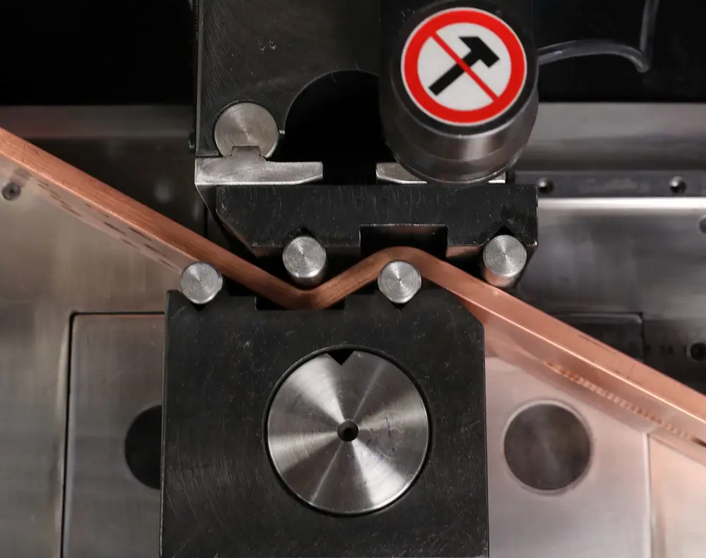
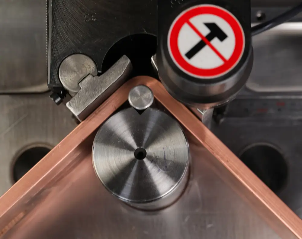
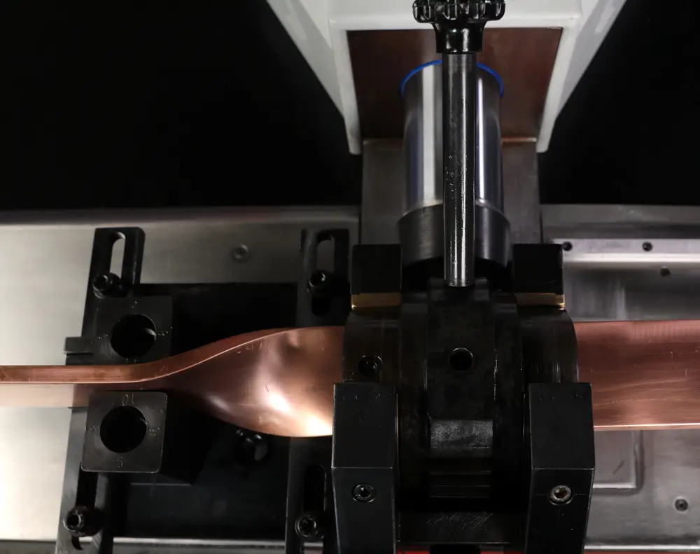
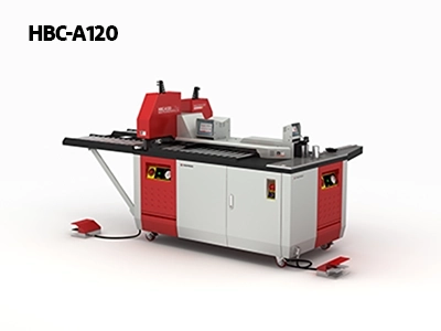
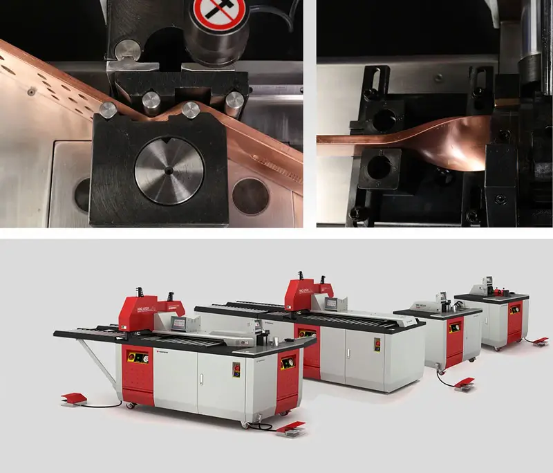
Every component in the list can be bought from a catalogue except the busbar. Its geometry exists only for that lineup, so fabrication cannot start until the arrangement is frozen. That places it at the end of the critical path with the least float.
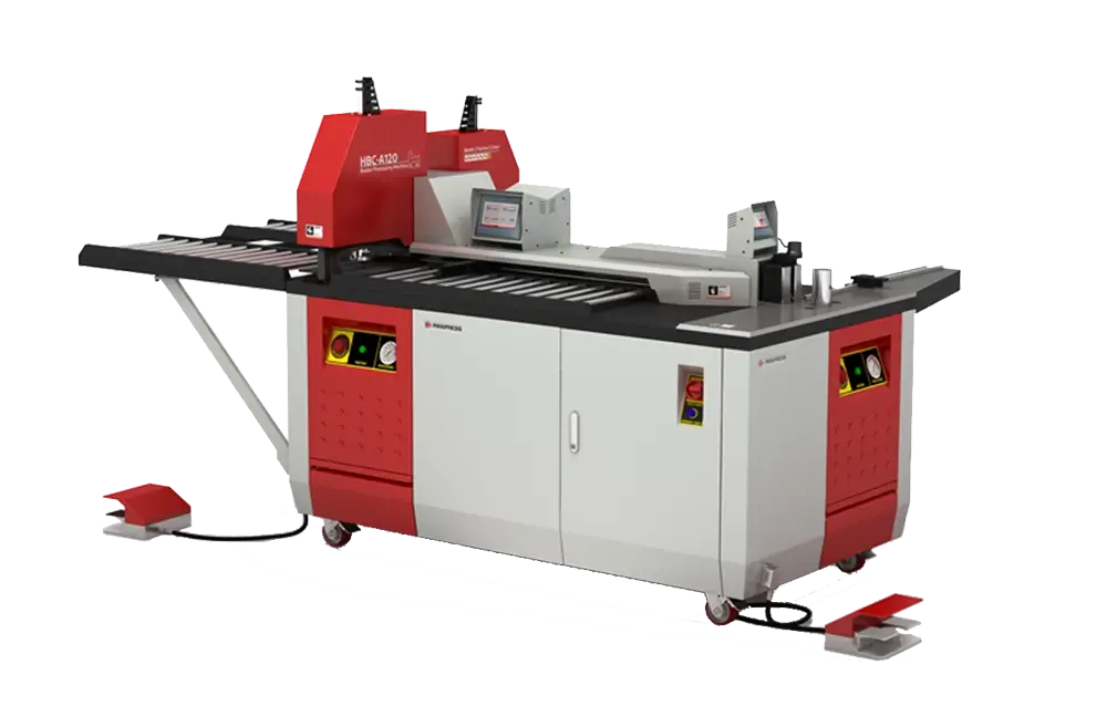
For panel builders, that makes bar capacity the constraint that most often decides whether a promised date holds. It is either done in-house, competing with everything else in the shop, or subcontracted, in which case an external lead time lands on the tightest part of the schedule.
If bar fabrication is where your LV panel schedules slip, send a drawing and a monthly volume and we will come back with a machine recommendation.
The busbar often connects to the load through a short branch conductor. Find out what a tee-off is and why its geometry matters.
Conclusion: What Is Electrical Panel Design
The process runs in dependency order: load, fault level, protection, conductors, enclosure, layout, verification. Each step constrains the next, and revisiting an early one after a later one has been fixed is where projects lose time.
The inputs decide everything. A design started without a confirmed load schedule, fault level and earthing arrangement is a design that will be done twice.
For a broader view of how modern assemblies have developed, see how modern switchgear has evolved beyond the breaker.



Rate this article
Choose a rating from 1 to 5 stars.
No ratings yet