

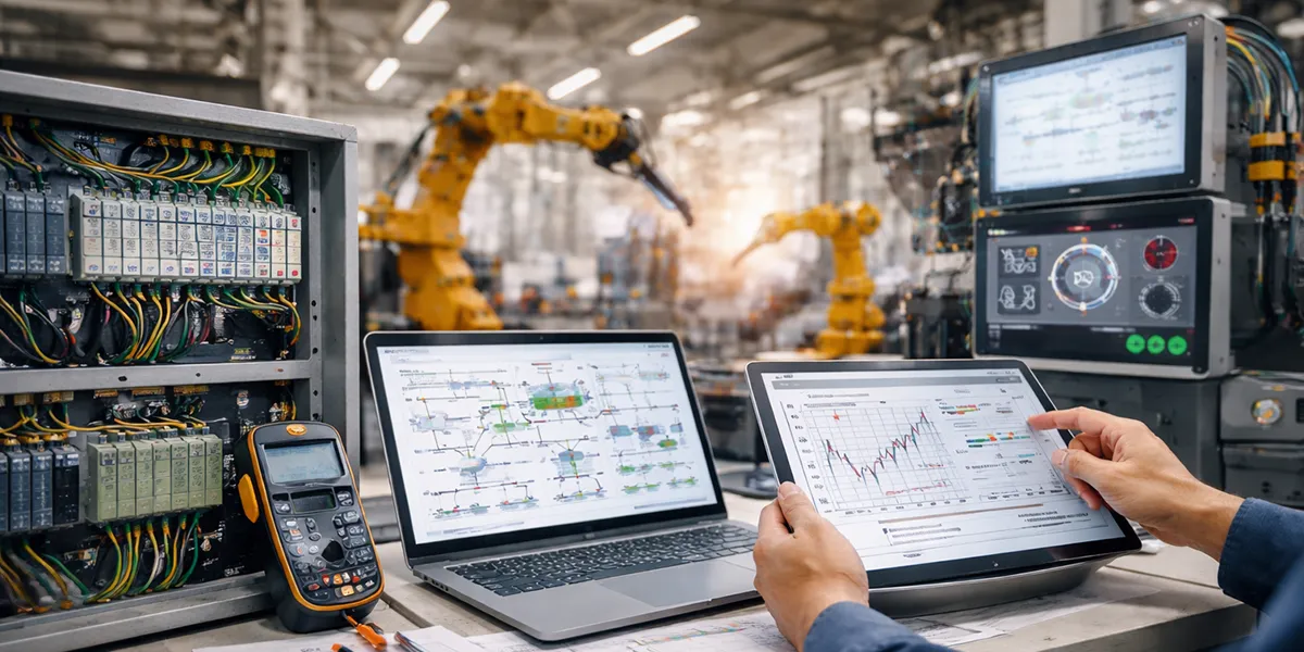





What Is an Industrial Control System?
An industrial control system (ICS) is the combination of hardware, software and networking used to monitor and control an industrial process. It covers everything from the sensors that measure the process, through the controller that decides what to do, to the final elements — valves, motors, drives — that act on it.
The term is a category rather than a single product. In practice it covers three main architectures, which are covered in detail below:
- SCADA — supervisory control and data acquisition, for assets spread across a wide geographic area
- DCS — distributed control systems, for continuous process control within a single plant
- PLC — programmable logic controllers, for discrete logic, sequencing and machine control
Alongside these sit the supporting devices that make them work: remote terminal units (RTUs), human-machine interfaces (HMIs), intelligent electronic devices (IEDs), and separate safety instrumented systems (SIS) where the process carries risk to people or plant.
Every one of them does the same fundamental job. Measure the process, compare the measurement against a target, and act on the difference.
The Main Types of Industrial Control Systems
The three architectures are not interchangeable. They differ by geographic scope, control philosophy and how they behave when communications fail.
| Characteristic | SCADA | DCS | PLC |
|---|---|---|---|
| Primary purpose | Supervisory monitoring and control of dispersed assets | Continuous closed-loop process control at one site | Discrete logic and sequencing |
| Geographic scope | Wide area — kilometres to hundreds of kilometres | Single plant or site | Single machine, cell or skid |
| Control philosophy | Operator-initiated, event-driven | Automatic, process-state-driven | Deterministic scan cycle |
| Behaviour on comms loss | Designed for it — field units run standalone | Low tolerance; assumes a reliable local network | Not applicable; I/O is local |
| Field devices | RTUs, PLCs, IEDs | Distributed controllers and I/O | Local I/O modules |
| Typical industries | Pipelines, water, power transmission, rail | Refining, chemicals, power generation, pharmaceuticals | Automotive, packaging, materials handling |
| Introduced | 1960s–70s, matured in the 1980s | 1975 | 1968 |
SCADA (Supervisory Control and Data Acquisition)
SCADA is the architecture used where the process is spread out. A pipeline runs for hundreds of kilometres. A water network covers a city. A transmission grid spans a region. In all three cases you cannot run I/O cable back to a single control room, so control is pushed out to the field and the central system supervises rather than executes.
How SCADA Differs from DCS
The distinction that matters most is what happens when communications drop.
A DCS assumes its network is reliable and fast. Controllers exchange data continuously, and the architecture is engineered around that assumption.
A SCADA system assumes the opposite. Field units — RTUs or PLCs — hold their own logic and keep running independently if the link to the master station is lost. Data is buffered locally and uploaded when the link returns. That is why SCADA suits satellite, radio and cellular links that a DCS could never tolerate.
The second difference is control philosophy. A DCS runs closed loops automatically and continuously. SCADA is largely supervisory: it presents the state of the system to an operator, who initiates changes. Automatic control still happens, but it happens locally at the RTU or PLC, not at the master station.
SCADA System Components
- Field instrumentation — sensors and final elements at each remote site
- RTUs or PLCs — local controllers that acquire data and execute local logic
- Communications — leased line, radio, cellular, satellite or fibre, often mixed within one system
- Master station — the central servers that poll field units, alarm on exceptions and archive data
- HMI — the operator graphics, trends and alarm displays
- Historian — long-term storage of process data for analysis and reporting
Industrial Control System Design: Methods and Approach
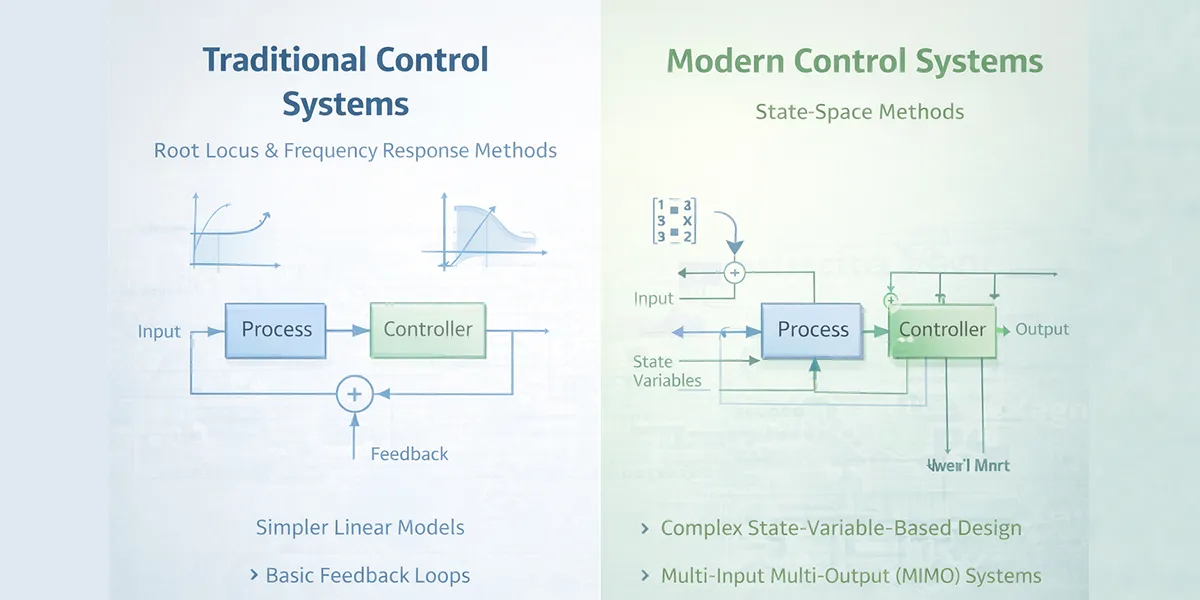
Real control systems are usually nonlinear, but if their behavior can be approximated using linear mathematical models, structured design methods can be applied. From a practical point of view, the specified performance requirements of the system determine the design method.
If the performance requirements are expressed in terms of transient response characteristics or frequency-domain criteria, there is no choice but to follow root locus or frequency response methods. If the performance requirements are expressed in terms of indices based on state variables, modern control methods must be used. Designing a control system based on root locus and frequency response approaches is an engineering task; however, in designing a system based on modern control theory (state-space methods), mathematical formulation of the problem and application of mathematical theories are used to solve it. In this case, the system can be multi-input multi-output, and even time-varying.
In modern control theory, you can start from a performance index and constraints imposed on the system and design a stable system using a completely analytical method. You can create a control system that is optimal with respect to a performance index, and this is one of the advantages of this method. Systems that can be designed using traditional methods are usually single-input single-output, linear, and time-invariant systems. By following proven patterns and trial and error, you can satisfy all performance criteria.
After designing the system, test it to see whether the designed system has the desired characteristics or not. If the answer is negative, repeat the design process by adjusting a parameter or changing the configuration until the desired specifications are obtained. Although this design method is trial and error, engineering intelligence and knowledge play an important role in successfully applying this method.
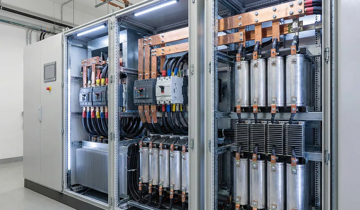
Usually, it is better for the designed system to have as little error as possible in response to input signals. In this respect, the damping of the system must be reasonable. The dynamic behavior of the system should be relatively insensitive to small changes in system parameters. Undesirable disturbances must be properly attenuated. In general, the high-frequency part must be attenuated so that high-frequency noises such as (sensor noises) are attenuated. If the frequencies of noise and disturbances are known, you can use band-stop filters to remove them. On the power side the equivalent problem is supply distortion, which is handled by harmonic filters rather than by the control algorithm.
If designing the system is equivalent to choosing among several alternative systems, the selection can be made based on considerations such as overall performance, cost, volume, and weight. In industrial control system equipment, the goal is to design and implement control loops such as temperature, pressure, level, and flow control loops in industrial processes.
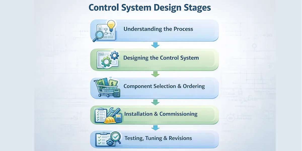
Stages of designing and implementing industrial control loops
In general, the stages of designing and implementing industrial control loops to control a specific behavior of various processes are as follows:
1- Correct and accurate understanding of the process
2- Presenting an initial control plan, including selecting an appropriate controller, designing the controller, and performing theoretical calculations
3- Determining and ordering the required components and parts to implement the initial plan based on required specifications and with economic considerations
4- Revising the plan if some parts are unavailable and replacing them with available parts
5- Installation, commissioning, and testing of components and parts
6- Cold commissioning of the control loop and performing initial tuning
7- Revising the plan if it is incomplete or if problems occur
8- Hot commissioning of the control loop while observing safety considerations and performing final tuning
9- Revising the plan if problems occur
10- Documentation and recording the final specifications of the design and components
A temperature control loop on a tank illustrates the sequence. The tank temperature is first measured and sent to the controller. By comparing the measured value (Process Value) with the desired value (Set Point), the error signal is determined. Based on the error signal and the performed settings, the controller sends the control command to the control valve, as a result of which the steam valve is adjusted and the tank temperature is corrected. The same loop discipline applies to every controlled variable in a plant, and it depends on the surrounding industrial electrical panel components being correctly specified.
This article serves as a valuable resource for those seeking detailed information on control loops.
Alarm devices
The occurrence of faults is an inseparable part of industrial control systems. Announcing an alarm when a fault occurs increases your attention and sensitivity in monitoring the correct execution of processes. Fault detection is performed by alarm devices. In an alarm device, the occurrence of each fault is indicated by an indicator.
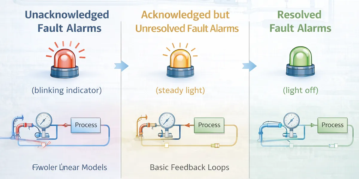
In general, depending on the fault status, three different alarms are given:
1- Alarms related to unacknowledged faults
In this case, when a fault occurs, the related indicator turns on in a blinking mode. Also, in this case, the fault occurrence can be detected by generating sound.
2- Alarms related to acknowledged but unresolved faults
When the fault is acknowledged but the fault condition still remains, the alarm device changes from blinking to steady illumination.
3- Alarms related to acknowledged and resolved faults
When the fault condition is removed, the steady alarm light turns off. One of the important issues in alarm system design is fault grouping. For example, consider a simple hydraulic system: the occurrence of a fault in each of the three conditions of pump stop, hydraulic pressure drop, and tank level drop is detected by an alarm device.
An alarm caused by pump stoppage leads to an alarm for hydraulic pressure reduction. On the other hand, low hydraulic pressure causes the pump to stop to prevent damage and losses. Similarly, an alarm for low tank level leads to an alarm for pressure reduction and consequently pump stoppage. If these alarms are placed in one group, then the initial alarm is displayed and subsequent alarms are ignored, or they are placed in a queue. Then, without being misled, you can find the root cause of the fault. Fault detection at the electrical layer works the same way — an upstream trip masks the downstream cause, which is why overcurrent protection and device coordination are designed as a hierarchy rather than device by device.
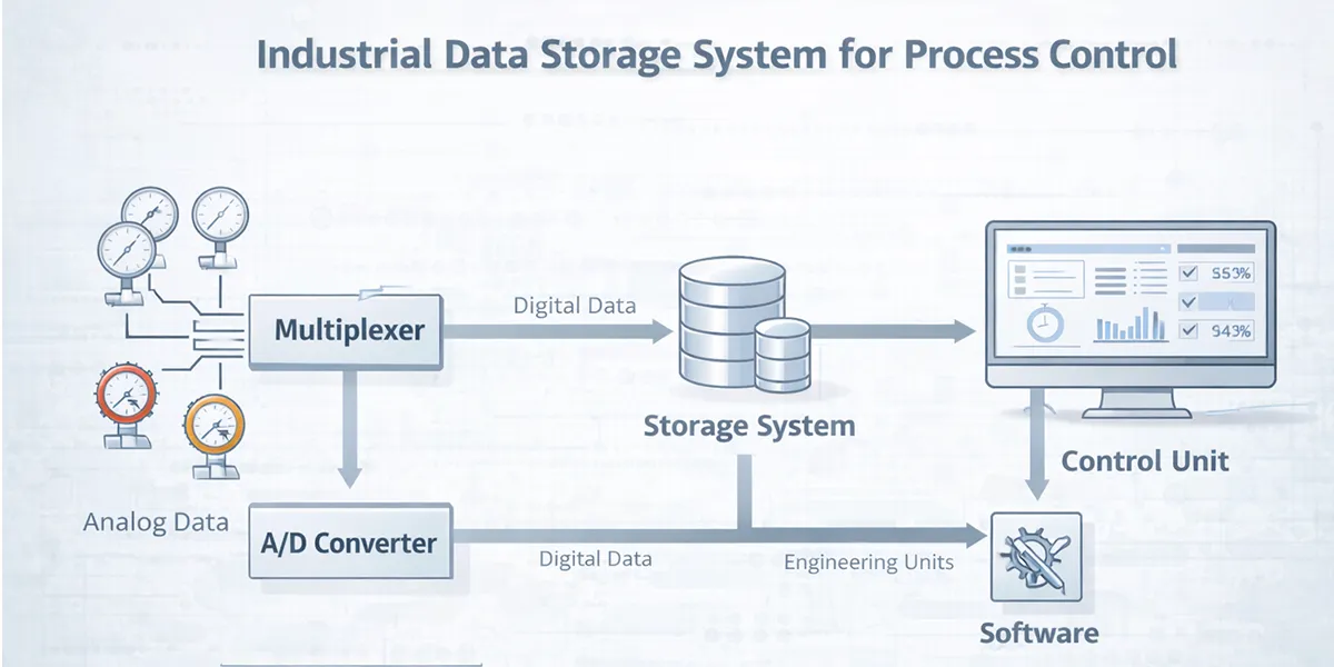
Storing information related to operating variables in automation system design
One of the important issues in automation system design is documenting information related to the design and information related to the running process. In an operating industrial process, a large volume of data and information is produced.
Data and information related to operating variables are used to analyze process performance and determine efficiency and process output. Therefore, storing and recording them is very important. Information storage is usually performed by local computers and the central control room computer. However, if using a computer for process control is not possible or necessary, then industrial systems are used for data storage.
Designing an industrial system for data storage
In designing an industrial system for data storage, the following are considered:
1- Storing analog and digital values of a process at normal time intervals
2- Checking alarm conditions and storing the process status at the time of alarm occurrence
3- Recording events and their occurrence times
The resulting data are usually stored on a compact disc and also printed for assurance, thus creating a set of information that can be accessed again.
In a typical data storage system, analog data are read through a multiplexer and then sent from a sampling unit. Analog data are converted by analog-to-digital converters before entering the data storage system. Then, using the control unit software, they are converted into engineering units such as degrees Celsius. To perform this conversion, the upper and lower limits are first specified, and then a linearization subroutine is used.
Actuators and final elements
The last element of the control loop of a process in different types of control systems is the final element. A control loop begins with measuring the process output and ends with applying the input command to the process by the controller. The controller command is transmitted to the controlled process by the final element. In industrial processes, valves are usually used as final elements.
Moving the final element, such as opening and closing a valve, requires energy consumption. The command sent from the controller is a control signal that usually does not have the required energy to move the final element. Therefore, this command is amplified and applied to the actuator; then the actuator moves the final element. The final element and its related actuator are usually offered together, and solenoid valves are common examples.
In general, control system types are classified as follows:
-
- Direct Digital Control (DDC)
- Distributed Control System (DCS)
- Programmable Logic Controllers (PLC)
- Fieldbus Control Systems (FCS)
| Features | DDC | DCS | PLC | FCS |
|---|---|---|---|---|
| Control Architecture | Centralized | Semi-Distributed | Centralized/Distributed | Fully Distributed |
| Processing Type | Digital | Semi-Digital | Digital | Fully Digital |
| Data Transfer Rate | Medium | High | High | 31.25 Kbit/Sec |
| Wiring Cost | High | Medium | Medium | Low |
| Expandability | Limited | High (Modular) | Medium | High |
| Fault Isolation | None | Yes | Limited | Yes |
| Diagnostics Capability | Limited | High | Medium | Very High |
| I/O Cards Required | Yes | Yes | Yes | No |
| Maintenance Cost | High | Medium | Low | Low |
| Year Introduced | 1960s | 1975 | 1968 | 1990+ |
| Best Suited For | Simple Systems | Complex Processes | Logic Control | Industrial Processes |
| Programming Complexity | High | Medium | Requires Expertise | Simple (Function Block) |
Direct Digital Control (DDC)
One of the types of control systems is direct digital control, or DDC, which was used from the early 1960s to support analog systems. In DDC systems, the operator communicates with the system via a keyboard and display. In this system, all components including various sensors and actuators are directly connected to the central computer, and all of them receive or send their communication signals from or to the computer. The central computer is capable of processing a large volume of variables, but with excessive growth of information and the creation of complex loops, the speed and efficiency of the computer decreases and causes problems in the system.
Some reasons for the weakness of direct control systems
1- High maintenance cost
2- Shutdown of the entire system in case of a fault in the central processor
3- Due to the use of only one processor in the system, programming it is difficult
4- High wiring and cabling cost
5- Inefficiency over long distances
6- Difficulty of fault detection in the system by technicians
Distributed Control System (DCS)
The distributed control system, or DCS, arrived in 1975, when Honeywell launched the TDC 2000 and Yokogawa launched CENTUM. The TDC 2000 was the first system to use microprocessors to perform direct digital control as an integrated part of the system, and it superseded the centralised DDC approach that preceded it. A distributed control system is one of the types of control systems in which operation is distributed instead of being concentrated at one point.
A distributed control system consists of a number of microprocessor modules that work together to control and monitor the operation of a system. Computers are distributed according to the geography of the site; therefore, this reduces installation and wiring costs.
DCS is a computer network, but it differs from existing home or office networks because, in DCS, unlike what is seen in batch processing on office or home computers, real-time processing is involved.
The difference between these two processing methods is in how their programs are executed. In ordinary computers, processing is such that at a given time only one program runs. This program starts complex computations with a fixed and specific set of data and eventually ends with desired results, and when processing is finished the program stops to receive a new command for re-execution with a new set of data.
In the real-time processing method in a distributed control system, processing also starts with a fixed set of data, with the difference that the same program execution is continuously repeated and refreshes the data based on the data from the previous stage. For example, automatic vehicle speed control can be considered a real-time function. Control starts with a fixed speed data, and at each stage the vehicle speed is sampled, and based on the difference from the desired speed, control signals for opening and closing the fuel throttle are applied. A DCS controller also works in this way, meaning it continuously samples hundreds or thousands of controlled systems and repeats calculations based on a defined plan for the relevant systems.
Physical data received from the environment can be divided into two main groups:
- a) Analog data:
This type of data changes continuously. Analog data are analyzed through control loops and software which, depending on need, may include proportional or PID controllers, and appropriate output signals are issued. - b) Discrete data:
Working with them is simple, and based on received signals and logical relations, they turn the input off or on.
To receive data from the environment, DCS, like all programmable logic controllers, requires a series of elements such as thermometers, pressure gauges, and ammeters. The values of the elements are converted into electrical signals, and DCS reads them and converts them to digital. The obtained data are used in the following:
- Control loops (feedbacks) for analog control
- Execution of logical programs to issue on/off instructions
- Displaying values on the monitor screen
- Preparing reports on system status
- Announcing danger in abnormal conditions of the controlled system and other operations that can be defined according to the system type
Advantages of a distributed control system compared to older systems
- Expandability and adaptability due to the modular nature of the system
- High control capability because the process control algorithm can be changed easily
- Integration of system functions
- Easy maintenance after installation
- Unlike a centralized system, in DCS, because control is divided, if one module fails, control on other sections continues without any defect; this phenomenon is called Fault Isolation.
DCS systems have expandability. In a central control system, expanding the system requires replacing the central processor and purchasing a more advanced system, but in DCS you can expand control performance by adding control modules.
DCS programming is done in high-level environments. This is unlike PLC controllers, where writing their programs requires familiarity with microprocessor systems.
As previously explained, DCS can consist of many control modules that operate independently and simultaneously; in addition, it has fast communication capability between its modules through communication lines with the data highway in real-time.
Types of DCS Architecture
DCS platforms are usually classified three ways: by generation, by redundancy configuration, and by network topology.
By generation. First-generation systems (1975 onward) were fully proprietary — proprietary controllers, proprietary data highway, proprietary operator stations. Second-generation systems opened the supervisory layer to standard PCs and Ethernet while keeping the control layer proprietary. Third-generation systems are fieldbus-native and increasingly built on commercial networking throughout, with the proprietary element narrowed to the controller firmware and the engineering environment.
By redundancy configuration. The level of redundancy is a specification decision, not a product tier:
- Simplex — no redundancy; a controller failure stops that section
- Redundant controllers — a hot standby CPU tracks the primary and takes over on failure without a process bump
- Redundant I/O — duplicated cards and, in some cases, duplicated field wiring
- Redundant networks — dual data highways on separate physical paths
- Fully redundant — all of the above, typical of refining and offshore
By topology. Older systems used a single data highway with controllers hung off it. Modern platforms generally use a switched, ring or dual-star Ethernet backbone, which removes the single shared bus as a bottleneck and a failure point.
The major platforms in current service are Honeywell Experion PKS, Yokogawa CENTUM VP, Emerson DeltaV, ABB 800xA and Siemens PCS 7. Platform selection is usually driven by installed base at the site, industry-specific requirements and lifecycle support rather than by feature comparison.
DCS hardware
The hardware of any DCS system can be divided into the following general components:
- Controller and processor unit
- I/O interface circuits
- Communication interface channels and circuits
- Redundancy (backup)
- Diagnostics (fault finding)
DCS controller and processor unit
The controller and processor unit is used to implement control algorithms on appropriate inputs and outputs to operate the relevant process. Due to the need to execute complex and detailed algorithms in a small time unit, the necessity of using a powerful processor in this section is evident.
Implementing these algorithms requires special simulation and testing equipment, sufficient mastery of machine language or application languages of the used processor, all of which make the use of units based on Intel series processors and cards based on PC architecture increasingly justifiable.
DCS I/O interface circuits
These units are responsible for receiving information from transducers and sensors or applying results from control logic to other components of the control system such as actuators, valves, and so on. In a large control system, these units must at least have the following capabilities:
- Full isolation
- Minimum adjustment capability
- Internal fault detection and assurance of correct operation by the unit itself
- Ability to communicate with the main processor
- Ability to implement some preprocessing
- Online replacement and fault finding
- Ability to be used as backup
- Acceptable sampling speed
- Acceptable resolution and accuracy in analog-to-digital converters
Considering these needs, using processor-based circuits in such units is also inevitable. However, due to the limited scope of operation of each unit, it is possible to use less powerful or specialized processors in them. One of the major issues in these units is implementing full isolation.
In digital types, this isolation is possible using one of the simplest methods, namely Opto Isolation, but in analog types, due to the diversity and expected accuracy of such systems and also the self-adjusting capability of these components, the discussion becomes somewhat more complex and difficult.
Communication interface circuits in a DCS
One of the most important and at the same time most complex parts of a DCS system is its communication interface circuits. These networks are divided into different sections. Among these sections, the following can be mentioned:
- Communication network between I/O cards and processor and controller units
- Communication network between different processor and controller units
- Communication network between HMI equipment and controllers
- Communication network between DCS systems
Backup (Redundancy) in control systems
One of the important topics in control systems is operational safety and system availability over time. For this purpose, Redundancy systems are used. This system is implemented at all levels of system hardware such as I/O units, communication networks, power supplies, and so on, depending on the nature of the process and its security level.
Practical implementation of Redundancy units is another major challenge of large systems, because, due to the real-time nature of the sections, components must operate in such a way that during replacement no shock is introduced to the system, and replacement is hot in service, and at that moment all information and performance of other components are available. This requires complete information communication between these components, and also different replacement mode conditions must be precisely defined for the system.
Fault finding or debugging (Diagnostics) in DCS systems
Another matter that must be considered in building and implementing a DCS system is automatic fault finding and self-diagnostics in such systems. These diagnostics must include all hardware sections such as controller units, I/O cards, communication networks, HMI equipment, and so on. For this purpose, using specific algorithms and applying various measures in hardware design, you can achieve this important goal. Usually, the diagnostics scope of each section must at least include fault detection and notifying the operator or system engineer to resolve it.
- User terminals
- Operator terminals
This part is the interface between the operator and DCS. Data on the display are reviewed, and the operator, based on this information, communicates necessary commands to the system. Information is entered through mouse, keyboard, touch monitors, and operator keyboards. The operator keyboard, which is not seen in ordinary systems, is a keyboard by which pressing each key related to a specific control system action activates specific conditions in the computer and thus performs the related action. In the operator keyboard, each key is for a specific task, and its function is similar to hot keys in ordinary keyboards.
Engineering terminals
In appearance, they are like operator terminals and differ only in software, but if needed they can also be used in place of them. However, they are usually used for the following purposes:
- a) Settings related to consoles and basic information
b) Changing main and initial information
c) Installing application software for discrete control systems
Engineering terminals, unlike operator terminals, are usually used offline.
Software and standards
Over the past two decades, fundamental activities have begun around standardizing communication protocols globally. The International Organization for Standardization (ISO) began work on the OSI (Open Systems Interconnection) model in the late 1970s and published it as ISO 7498 in 1984.
How DCS communicates with different systems
In many applications, DCS must communicate with computers and microprocessor systems:
- When connecting and exchanging information with management information system computers
- Connecting and exchanging information with modeling computers
- When connecting with different PLC types
- And in general, communicating with computers that have another type of operating system
Therefore, it is necessary for transmitted information to be translated first. For this purpose, hardware called a Translator Box or Host Gateway is used. This hardware must be programmed for translation. Therefore, these hardware units, depending on the translation type, have different drivers that establish a Master/Slave relationship between themselves and DCS. For example, when a DCS is connected to a PLC, the DCS normally acts as master and exchanges information with the PLC through the gateway and a protocol-specific driver. This issue is very important in terms of coordination when upgrading the control type of a large process to DCS.
Master and Slave Concepts
In a control system, the device that reads inputs, writes outputs and requests information from other devices is the controller — historically called the master or server. The device that supplies information and responds is the field device — historically the slave or client. Most vendors and standards bodies have moved to controller/device or client/server terminology, though the older terms still appear in legacy documentation and protocol names. When sensors are connected to a network they normally act as field devices, but a sensor programmed to take a coordinating role in a larger system can act as a controller.
Programmable Logic Controllers (PLC)
A programmable logic controller is a ruggedised industrial computer that reads inputs, executes a stored program in a deterministic scan cycle, and writes outputs. It replaced hardwired relay panels, and it remains the workhorse of discrete control.
The PLC predates the DCS by seven years. In 1968, Dick Morley and his team at Bedford Associates built a solid-state sequential logic solver for General Motors, designated the Modicon 084 after the company’s 84th project. It was demonstrated to GM’s Hydra-matic Division in November 1969 and the first commercial unit was delivered in 1970, replacing the large electromagnetic relay panels GM had been using. Ladder logic — which borrowed its symbols from electrical schematics — was what made it usable by working electricians rather than programmers.
How a PLC Executes
A PLC runs a fixed, repeating cycle:
- Read inputs — the state of every input is captured into an image table
- Execute program — logic runs top to bottom against that snapshot
- Write outputs — results are applied to the output modules
- Housekeeping — diagnostics, communications, then repeat
That determinism is the point. A PLC scan completes in a known time, typically single-digit milliseconds, which is what makes it suitable for interlocks, sequencing and machine safety.
PLC Programming Standards
Programming languages are standardised under IEC 61131-3, which defines five:
- Ladder Diagram (LD) — relay-style logic, still the most widely used
- Function Block Diagram (FBD) — graphical blocks, common in process work
- Structured Text (ST) — Pascal-like, for calculations and complex logic
- Instruction List (IL) — assembler-like, now deprecated in newer editions
- Sequential Function Chart (SFC) — for step-based batch and sequence control
A single project commonly mixes several: ladder for interlocks, structured text for maths, sequential function chart for the batch sequence.
Where PLCs Fit Against DCS
The distinction is not capability — modern PLCs handle analog loops perfectly well — but architecture and engineering model. A DCS is engineered as one integrated system with a common database, common HMI and built-in redundancy. A PLC-based system is assembled from a controller, a separate SCADA or HMI package, and separately configured networking.
For discrete manufacturing, sequencing and machine control, the PLC is the default. For large continuous processes with hundreds of analog loops, the integration of a DCS usually wins. Between those two poles the choice is driven by installed base, engineering preference and lifecycle support rather than raw capability.
Field control system (FCS)
Fieldbus changed how field devices connect, but it is a communication layer rather than a rival architecture. Modern DCS platforms are fieldbus-native, so the practical question on a new project is which fieldbus protocol a DCS will use, not whether to choose fieldbus instead of a DCS.
Differences between FCS and DCS
This system has the following fundamental differences compared to DCS:
- DCS is a semi-distributed system, while fieldbus is fully distributed.
- DCS is a semi-digital system, while fieldbus is fully digital.
- Fieldbus is a complete architecture for process control and is less complex than DCS.
- Fieldbus does not need analog/digital cards and interfaces because communications are essentially digital.
- Fieldbus does not need controller (CPU) cards because controls are performed in field devices.
- Fieldbus does not need a data gateway.
- The benefit of fieldbus is in reducing control room equipment such as I/O racks and conditioning cards. In practice, a fieldbus-enabled DCS delivers more value than a fieldbus-only installation, because the supervisory and historian layers still have to come from somewhere.
Advantages of FCS field control systems
Lower price of FCS compared to DCS
An FCS system has a lower initial cost than a similar DCS. Eliminating wiring, field instruments, and control room equipment that were typically used in DCS contributes to this cost reduction. It also brings increased information such as diagnostics information and higher accuracy through digital communications.
Fewer instruments
Many fieldbus transmitters are multi-variable, such as two-channel temperature transmitters that calculate two temperatures and send both in real time.
Diagnostics capability
Digital communications enable access to structural information, transmitted data from field instruments, and fault details from the control room. Automatic diagnostics of each field instrument quickly reports errors or problems and enables rapid viewing of faults of different devices even before any damage occurs. Hardware faults such as sensor and actuator faults, as well as software faults such as configuration faults, can be reported and resolved without the need for manual system troubleshooting. Therefore, operators immediately determine, without going to the field, whether a problem in the process is related to field components or not.
Due to the digital nature of signals, system reliability increases through improved diagnostics.
Unlike DCS, the fieldbus system is completely digital from the transmitter to the digital input of a control valve. The presence of digital signals at the end of the control loop enables sending very accurate and complex data to the process. Fieldbus communication cables can extend hundreds of meters without noise or common distortions in analog communications. In addition, computational or control variables exchanged between function blocks include, besides value, a status containing information about signal limits and its quality.
Simpler and easier use
Configuration of all components using the function block method is done in one way, and there is no need to train different programming methods or programming languages, because all manufacturers, regardless of what device they have used, use a similar function block. For example, a temperature and pressure transmitter from different manufacturers operates based on similar fundamentals, which reduces complexity and operator training. In this system, all instruments are connected through a pair of wires that also provide electrical power and communicate and transfer required information through this path. Conductor selection still matters at that scale — see this guide to choosing the right wire for industrial installations.
Suitable data rate
The data transfer rate for FOUNDATION Fieldbus H1 and PROFIBUS PA is 31.25 kbit/s. That is deliberately modest — it is fast enough for process loops and slow enough to run power and signal over the same twisted pair. Higher-speed variants exist for backbone use: FOUNDATION Fieldbus HSE runs at 100 Mbit/s and PROFIBUS DP up to 12 Mbit/s. It should be noted that in most systems, even DCS, for Emergency Shutdown systems, a system other than the main system, usually PLC with better speed, is used.
Components of a fieldbus system
In a fieldbus system, connecting parts placed in the working field is simple. Usually, each part can be connected and wired in parallel with twelve other parts on one bus. Adding parts that make the system scalable is also easy. The system can also be expanded to meet new requirements. In many cases, parts can communicate with each other without needing an additional interface or cable. Since this system is open, various products from different manufacturers capable of connecting to this network are available.
Industrial Control Systems: Real-World Examples
The architecture that fits depends far more on the shape of the process than on the industry name.
| Application | Typical architecture | Why |
|---|---|---|
| Oil and gas pipeline | SCADA | Pump and valve stations spread over hundreds of kilometres; each must run independently if comms drop |
| Municipal water and wastewater | SCADA with local PLCs | Pump stations, reservoirs and treatment works across a city, largely unmanned |
| Oil refinery | DCS | Thousands of interacting analog loops in one location, running continuously for years between turnarounds |
| Power generation plant | DCS with a separate SIS | Continuous process, high consequence of failure, turbine protection kept independent of process control |
| Pharmaceutical batch plant | DCS with batch software | Recipe-driven sequences plus regulatory audit-trail requirements |
| Automotive assembly line | PLC networked to SCADA | Discrete sequencing and interlocking at machine level, plant-wide visibility above it |
| Packaging or bottling line | PLC with local HMI | Self-contained machine control; no plant-wide integration required |
| Building HVAC | DDC or BMS | Comfort control, modest loop count, cost-driven |
| Electrical transmission substation | SCADA with IEDs | Protection relays act locally in milliseconds; SCADA supervises and reports |
Two patterns show up repeatedly. First, SCADA and PLC are frequently used together — the PLC does the control, SCADA does the supervision. Second, safety functions are almost always separated from process control, so a failure in one cannot disable the other.
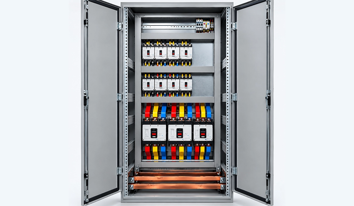
Electrical panels and switchgear sit underneath all of these, since every controller and every field device needs power distribution that is designed and verified for the duty.
Conclusion
Industrial control systems can be designed using traditional methods such as root locus and frequency response, or using modern state-space approaches based on state variables and performance indices. Successful implementation requires a clear understanding of the process, careful selection of components, systematic commissioning, and thorough documentation. Key practical considerations include error reduction, reasonable damping, disturbance and noise attenuation, and robust behavior against parameter variations. For industrial projects, choosing the right architecture (DDC, DCS, PLC, or FCS) should be aligned with performance needs, reliability, and economic constraints.
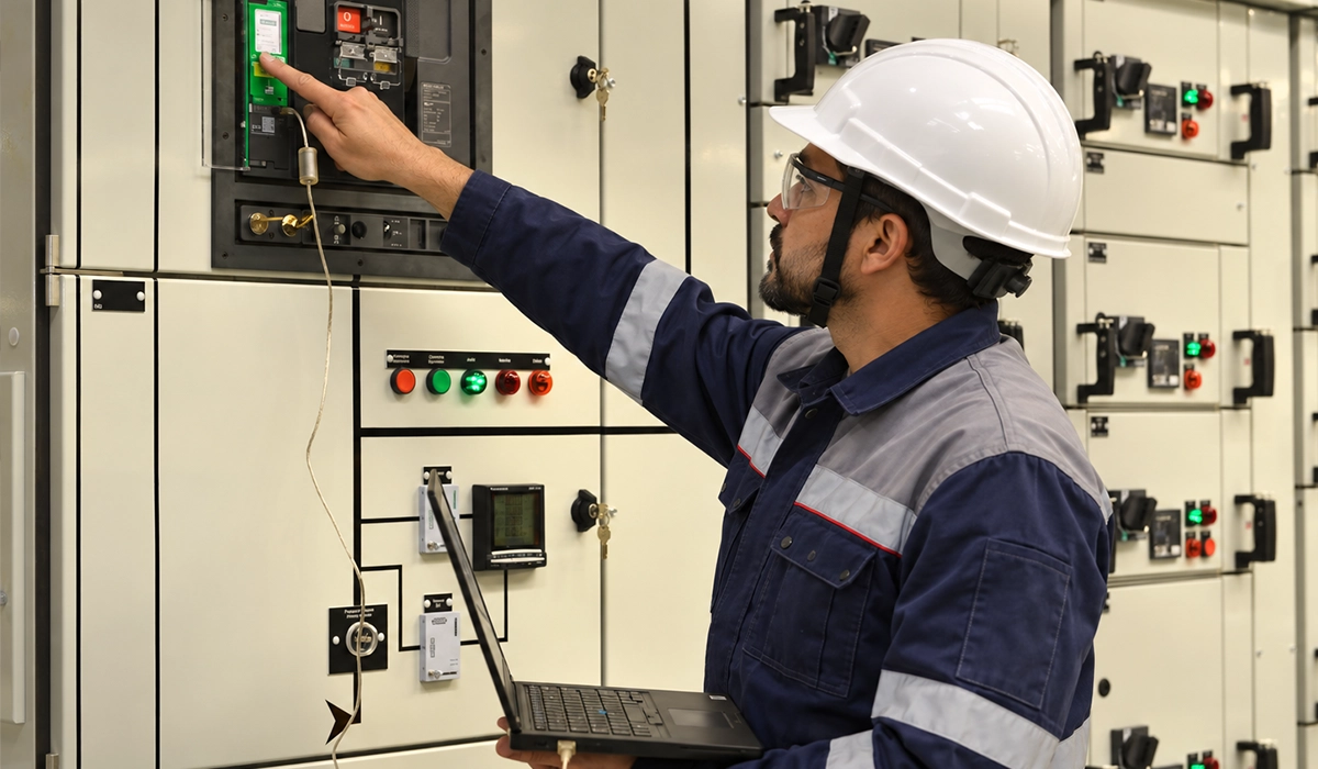
Whichever architecture is chosen, the controller ends up inside an assembly — a control panel, an MCC or a distribution board — and the quality of the power distribution inside that enclosure decides how well it performs over its life. Explore PAYAPRESS CNC busbar fabrication machines for busbar processing that supports IEC 61439 verification.


Rate this article
Choose a rating from 1 to 5 stars.
No ratings yet