


Prefer listening? You can play the audio version of the rest of this article below.
Protection Engineering in My Project Planning: Why I Had to Treat a “Simple Panel” Like a Real Engineering Job
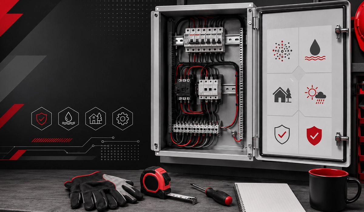
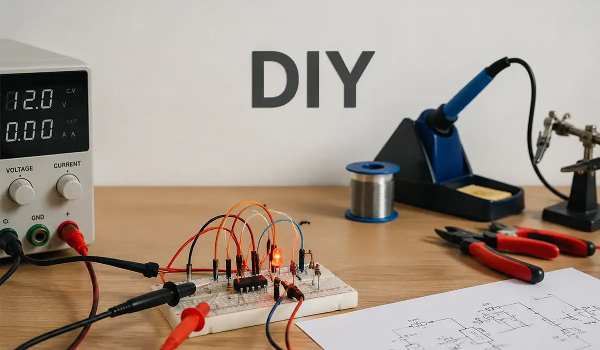
At first, I thought I was just building a neater power distribution box for my workshop. I wanted cleaner wiring, better labeling, and dedicated feeds for a VFD, lighting, and bench outlets.
But once I listed the loads—motor drive, SMPS supplies, a compressor starter, test instruments, and occasional heating loads—I realized this was no longer “just wiring.” It was a protection engineering problem.
I wrote three goals on paper before buying anything:
- Prevent damage (cables, devices, and my own mistakes)
- Reduce nuisance trips
- Make faults easier to diagnose
That changed everything.
I stopped thinking only in terms of “which breaker fits” and started thinking in layers:
- What kind of overcurrent can happen?
- What kind of surges can enter the panel?
- What harmonics will the VFD inject?
- Will my conductor geometry increase heating?
That mindset alone saved me time and money.
If you are looking for more information about electrical panels, it is recommended not to miss reading this article.
The Loads I Was Actually Designing For
My final panel included a mix of components from brands I trust for availability and documentation:
- Schneider Electric / Siemens miniature breakers and protection devices
- ABB contactor for a switching branch
- Danfoss / Delta-style VFD for a motor load
- Phoenix Contact / Weidmüller terminals
- Fluke handheld meter and later a borrowed power quality analyzer for troubleshooting
- Megger insulation tester during final checks
This wasn’t a factory panel. But the problems were very real—and very similar to industrial ones.
For a comprehensive understanding of panel components, we highly recommend reviewing this article.
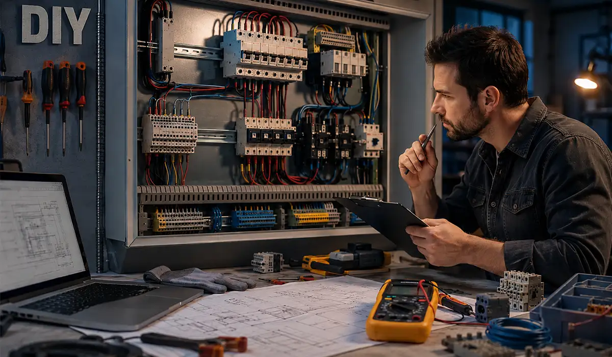
My First Mistake: Designing from Current Only
I initially sized protection mostly from nameplate current and cable ampacity. That was too shallow.
What I should have considered from day one:
- Inrush behavior
- Continuous load derating
- Harmonic distortion
- Coordination between upstream and downstream protection
- Surge environment (especially in a building with long cable runs)
That mistake led directly to my first nuisance trips.
Protection Engineering for Overcurrent: What Overcurrent Protection Means in Real Life (Not Just in Definitions)
When I first learned protection, I treated “overcurrent” like one thing. It isn’t. That misunderstanding caused me to choose a breaker curve that looked correct on paper but behaved badly in practice.
In simple terms, overcurrent protection means protecting conductors and equipment from currents that exceed what they are designed to safely carry.
But in the panel, overcurrent showed up in different forms:
- Overload (too much current for too long)
- Short circuit (very high fault current, very fast)
- Ground fault (depending on system and path)
- Inrush-related temporary peaks (not always a fault, but can trip protection)
Once I separated those in my mind, my settings started to make sense.
What Is Overcurrent Protection?
My practical definition became this:
Overcurrent protection is the coordinated use of protective devices and settings to disconnect or limit excessive current before conductors, insulation, or equipment are damaged.
That includes:
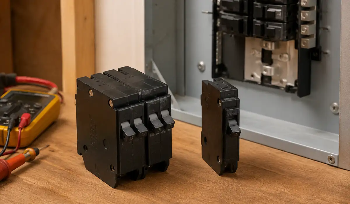
- MCBs / MCCBs
- Fuses
- Motor protection breakers
- Electronic trip units
- Relays (in larger systems)
In my small setup, the core idea was still the same as in an industrial panel: protect the cable first, then the equipment, while maintaining usability.
What the Setting Value of Overcurrent Protection Means
This part confused me early on.
I used to think the “setting value” was just “the current where it trips.” That’s only partly true.
In real systems, the setting value can refer to different thresholds and timing behaviors, such as:
- Pickup current (the current level that starts the trip action)
- Time delay (how long the current must persist)
- Instantaneous trip threshold (for severe faults)
- Thermal/long-time settings (to reflect heating behavior)
In my project, I had a branch feeding a motor drive and another branch for auxiliary loads. I initially set one protective device too tightly because I was afraid of overheating. The result? Startup nuisance trips.
What fixed it was not “making the breaker bigger blindly.” It was:
- confirming cable sizing,
- checking actual measured current,
- understanding startup/inrush behavior,
- and adjusting the protection setting (or curve type) appropriately.
That was a big lesson: a bad setting can make a good device look defective.
Quick Quiz I Now Use With Apprentices and DIY Friends
I actually wrote this on a sticky note while troubleshooting:
Quiz: Which is the least potentially damaging type of overcurrent (if cleared/managed properly)?
A) Short circuit
B) Overload
C) Arcing fault
D) Ground fault
Answer: B) Overload (generally speaking)
Why?
- Overloads are usually lower magnitude than short circuits
- They tend to cause thermal stress over time, not immediate explosive damage
- Protective devices often handle them through thermal/time-delay mechanisms
That said, overloads are still serious. I once ignored a “slightly warm” terminal feeding a continuous load. A week later, insulation discoloration proved that “slow damage” is still damage.
Overcurrent Events I Encountered in the Project
| Overcurrent Type | What It Looked Like in My Panel | Typical Risk Speed | My Fix |
|---|---|---|---|
| Overload | Motor branch running hot during long cuts | Medium (thermal buildup) | Measured actual current, adjusted protection curve, improved ventilation |
| Inrush peak (non-fault) | Nuisance trip at startup | Fast trip, but not true fault | Changed device curve / coordination |
| Suspected short (wiring error during testing) | Immediate trip after energizing branch | Very fast, high damage potential | Isolated branch, continuity check, corrected wiring |
| Loose terminal heating (current concentration) | Heat and smell before trip | Medium to fast | Re-terminated, torque checked, replaced damaged lug |
If the information related to overcurrent events was interesting and informative to you, researching arc fault breakers can be very engaging.
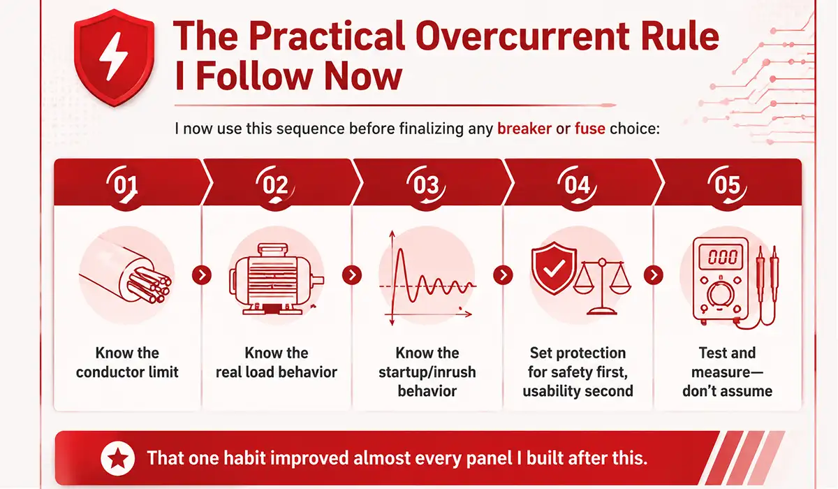
The Practical Overcurrent Rule I Follow Now
I now use this sequence before finalizing any breaker or fuse choice:
- Know the conductor limit
- Know the real load behavior
- Know the startup/inrush behavior
- Set protection for safety first, usability second
- Test and measure—don’t assume
That one habit improved almost every panel I built after this.
Protection Engineering for Surge and Insulation Coordination: The Point Where I Stopped Thinking Only About Breakers
My second big learning moment came when a thunderstorm (not even a direct strike near my building) caused strange behavior in one of my measuring devices and a power supply module.
Nothing failed dramatically, but the system started acting “haunted”:
- one display froze once,
- a small PSU had intermittent resets,
- and a VFD alarm history showed unexplained events.
That pushed me into surge protection and insulation coordination, which I had previously treated as “industrial-only topics.”
They are not.
What Is a Surge Arrester (and Why I Added One)
A surge arrester (in low-voltage panel practice often called an SPD – Surge Protective Device) is a device designed to limit transient overvoltages by diverting surge current and clamping voltage to a safer level.
My earlier mindset:
- “I already have breakers, so I’m protected.”
Wrong.
Breakers and fuses protect mainly against overcurrent, not fast transient overvoltages. A surge event can stress electronics without causing a normal overcurrent trip.
I added a properly selected SPD in the panel’s upstream section and paid more attention to:
- short connection leads,
- good bonding,
- proper earthing path,
- and the placement relative to sensitive devices.
That alone reduced weird behavior after utility disturbances.
If the details you gathered about surge protection were interesting and insightful, you may find diving deeper into modern electrical systems equally captivating.
What Overvoltage Category Means (and Why I Used It Wrong at First)
I used to read CAT II / CAT III / CAT IV markings on meters and assume they were just “quality levels.” They are not.
Overvoltage category describes the expected transient environment in different parts of an installation.
A simple way I now remember it:
- CAT II = local appliance-level circuits
- CAT III = distribution-level circuits inside buildings
- CAT IV = origin of installation / service entrance and outdoor conductors
My mistake was using a measurement accessory in a location that really belonged to a higher transient environment than I first assumed. That was a wake-up call.
In the project, this affected:
- test tool selection,
- probe selection,
- and my respect for where transients are most severe.
What Creepage Distance in an Insulator Means (And How It Bit Me in a Dusty Workshop)
I used to focus mostly on clearance (air gap). But creepage distance is different.
Creepage distance is the shortest path along the surface of an insulating material between two conductive parts.
Why it mattered in my workshop:
- fine dust,
- humidity swings,
- occasional oil mist,
- and long-term contamination on surfaces
A surface path can become more conductive over time, especially in dirty environments. In one early build, I routed conductors too close over an insulating support block and assumed “looks okay” was enough. It wasn’t my worst failure, but it was poor practice.
Now I pay much more attention to:
- insulator material quality,
- contamination risk,
- terminal spacing,
- barriers/shrouds,
- and layout that avoids tracking-prone paths.
The Insulation Coordination Lesson I Learned the Hard Way
Insulation coordination is basically making sure the insulation strength of your system (and devices) matches the expected voltage stresses—especially transient ones.
In practical DIY panel language:
- Don’t put sensitive electronics in the same “electrical neighborhood” without thinking about surges.
- Don’t assume spacing that looks visually generous is technically correct.
- Don’t mount an SPD and then wire it with long looping leads that reduce its effectiveness.
I redid my panel layout once just to improve:
- SPD lead length,
- separation of power and control wiring,
- and terminal spacing around higher-stress points.
It was worth the extra day.
Protection Engineering for Harmonics: How My VFD Turned a “Working Panel” Into a Troubleshooting Project
The panel worked. Then I added a VFD-driven motor and some electronic loads on the same distribution branch.
That’s when the fun started.
Symptoms appeared slowly:
- occasional nuisance trips
- extra heating in one conductor path
- buzzing in one device enclosure
- weird readings on a cheap meter
- more noise in control signals than expected
I first blamed the breaker. Then the cable. Then the VFD brand.
The actual issue was more subtle: harmonics.
What Harmonic Filters Are (and What They Actually Do)
A harmonic filter is a device or network designed to reduce harmonic distortion in electrical systems by attenuating or redirecting harmonic-frequency currents/voltages.
In practical terms, harmonic filters help:
- reduce THD (Total Harmonic Distortion)
- reduce extra heating in transformers/cables/conductors
- improve power quality
- reduce nuisance tripping and interference
- protect sensitive equipment from distortion-related stress
There are different types, but in workshop and industrial discussions you’ll usually hear about:
- Passive harmonic filters (L, C, sometimes R combinations, tuned/detuned)
- Active harmonic filters (power electronics that inject counter-harmonic currents)
- Line reactors / DC chokes (not full filters, but often very helpful with VFDs)
In my project, I started with a more modest step: improving input conditioning and layout, then later testing a filtering approach appropriate for the drive load.
For a comprehensive understanding of harmonic filters, we highly recommend reviewing this article.
Harmonic Filter Electrical Basics (Without the Textbook Pain)
I had to force myself to stop thinking of harmonics as “random electrical noise.”
Harmonics are frequency components at integer multiples of the fundamental frequency. Nonlinear loads (like many drives and SMPS units) draw current in a non-sinusoidal way, and that distorts current waveforms.
That distorted current can cause:
- heating beyond what RMS current alone suggests
- nuisance operation in protection devices
- voltage distortion across system impedance
- EMC headaches
In my case, the VFD input current waveform wasn’t pretty, and the effect became visible when the panel served mixed loads.
How Harmonic Filters Work (What I Saw in Practice)
The practical idea is simple:
- Passive methods create impedance behavior that reduces certain harmonic currents.
- Active filters sense distortion and inject compensating currents.
What I observed after improving the setup (including input conditioning and better separation/layout):
- lower apparent “electrical roughness”
- fewer nuisance events
- cooler operation in some conductor/terminal points
- more stable behavior on measurement devices
Was it magic? No. It was just finally acknowledging the system was nonlinear.
My Before/After Troubleshooting Snapshot
Here’s a simplified version of the trend I recorded during testing.
Illustrative Power Quality Trend (relative)
| Metric | Before Improvements | After Improvements | Result |
|---|---|---|---|
| Current THD | High | Moderate / Lower | Reduced harmonic distortion |
| Nuisance Trips | Frequent | Rare | Fewer unwanted breaker trips |
| Conductor Hotspot Complaints | Noticeable | Reduced | Lower thermal-risk complaints |
This was one of those moments where measurement beat opinion. I had argued for a day that the breaker was wrong. The waveform data told a different story.
Harmonics and Protection: The Connection People Miss
What changed my thinking was this:
Protection engineering and harmonics are connected.
A device can be correctly rated and still behave poorly in a distorted system if:
- heat rises unexpectedly,
- current waveform shape affects sensing behavior,
- or shared impedance spreads distortion into sensitive branches.
That’s why I no longer design “protection” and “power quality” as separate topics.
Protection Engineering for Skin Effect: Why Conductor Shape and Surface Area Started Mattering More Than I Expected
I’ll be honest: for a long time, I treated skin effect as a high-frequency theory topic that mattered to RF engineers, not workshop panel builders.
Then I started dealing with harmonics, switching edges, and conductor heating patterns that didn’t match my simple DC intuition.
That’s when skin effect stopped being a textbook word and became a practical design consideration.
What Is the Skin Effect?
Skin effect is the tendency of alternating current (AC) to concentrate more near the outer surface of a conductor as frequency increases.
At normal power frequency (50/60 Hz), the effect in small conductors may be modest. But as frequency increases (including harmonic components), current distribution becomes less uniform, which can increase effective AC resistance.
That means:
- more heat,
- less efficient conductor use,
- and more reason to think about conductor geometry.
The Question That Finally Made It Click for Me
One of the best conceptual prompts I encountered was essentially:
“What kind of circuits should use conductors with very large surface area relative to cross-sectional area?”
Once I understood skin effect, the answer became intuitive:
- High-frequency circuits
- Circuits carrying significant harmonic content
- Applications where AC resistance matters
- Busbar and power electronic layouts where current crowding/heating is a concern
This doesn’t mean “use huge flat metal everywhere.” It means conductor geometry matters.
What I Changed in My Panel Because of Skin Effect (and Harmonics)
In my project, I didn’t redesign everything into a high-end laminated busbar system. But I did make better choices:
- shorter conductor paths
- improved conductor routing and spacing
- avoiding unnecessary loops
- better termination quality (surface contact matters)
- in one section, using a conductor arrangement with more exposed surface compared to a single bulky path
The biggest surprise? Some of my “heating problems” were not just about current magnitude—they were about layout, contacts, and waveform content.
A Practical Rule I Use Now
If a circuit includes drives, switching power electronics, or significant harmonics, I ask:
- Is my conductor choice only sized for ampacity?
- Have I considered AC behavior and heating?
- Are my terminations and contact surfaces excellent?
That question has prevented several repeat mistakes.
If the information on skin effect and conductor geometry was engaging and informative for you, gathering more knowledge about busbar systems could be very exciting.
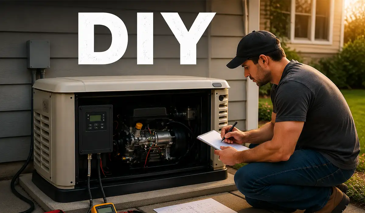
Protection Engineering in Final Assembly and Commissioning: The Checklist That Saved Me From Rework
By the time I rewired the panel for the second time, I stopped improvising and used a formal commissioning checklist—even for a DIY build.
That was one of the smartest things I did.
My Commissioning Sequence (Real-World Order)
- Mechanical inspection
- enclosure integrity
- gland entries
- strain relief
- spacing and routing
- Torque check
- terminals, lugs, breaker connections
- this alone fixed one heating issue in a previous build
- Insulation and continuity checks
- verify no accidental shorts
- confirm protective earth continuity
- Protection settings review
- confirm breaker/relay settings match cable and load intent
- verify no “temporary test settings” left behind
- Energize in stages
- main section first
- then auxiliary loads
- then VFD branch
- then combined operation
- Measure under real load
- current
- voltage drop
- temperature at terminals/conductors
- behavior during startup and stop cycles
- Observe for one week
- not just five minutes
- many faults appear only after heat, dust, and repeated cycles
If you are looking for more information about Protection Engineering, it is recommended not to miss reading this article.
The Commissioning Table I Wish I Used in My First Panel
| Check Item | Why It Matters | What I Found in This Project |
|---|---|---|
| Terminal torque | Loose joints create heat and false symptoms | One terminal needed re-torque |
| Protection settings | Prevents nuisance trips and under/over-protection | One branch setting was too tight |
| SPD installation lead length | Long leads reduce surge clamping effectiveness | I shortened routing on second layout |
| Separation of power/control wiring | Reduces noise and interference | Improved signal stability |
| Load measurement under operation | Nameplate assumptions are often wrong | Actual current differed from expected |
| Post-run thermal inspection | Finds issues before failure | Detected hotspot early |
Protection Engineering Lessons I Would Tell My Past Self
If I could go back and coach myself before this project, I’d say:
- Don’t trust nameplates blindly. Measure.
- Overcurrent settings are not just numbers—they are decisions about thermal stress and fault behavior.
- Breakers do not replace surge protection.
- Harmonics can make a “correct” panel behave incorrectly.
- Skin effect is not just classroom theory when harmonics and switching loads are present.
- Layout is part of protection engineering.
- Commissioning is not optional.
This project started as a cleanup job and turned into one of the best practical protection engineering lessons I’ve ever had.
Conclusion about Protection Engineering
What I love about DIY electrical projects is that they teach humility fast. A panel can look clean, have premium components, and still perform badly if the protection engineering is weak.
In my case, the breakthrough came when I stopped treating overcurrent, surges, insulation coordination, harmonics, and skin effect as separate textbook chapters. In real life, they interact. The wrong overcurrent setting can hide a harmonic issue. Poor layout can weaken surge protection. Conductor geometry and termination quality can worsen heating even when current seems acceptable.
The panel now runs cooler, trips less, behaves more predictably, and is easier to diagnose. More importantly, I trust it more—because I understand it more.
If you’re building or upgrading your own panel, don’t rush straight to assembly. Spend more time on the protection thinking. It feels slower at first, but it saves you from the most frustrating kind of work: tearing apart a finished panel to fix something you could have designed out on day one.
FAQ about Protection Engineering