


Prefer listening? You can play the audio version of the rest of this article below.
Generator Sizing for a Whole-House Backup Project
When I first started researching, I made the same mistake a lot of people make: I assumed my panel’s service size directly told me my generator size.
It does not.
My main panel was rated 200 amps, and I immediately thought, “Okay, I need a monster generator.” Then I started pricing 30–40 kW units and nearly closed the laptop.
That was my first lesson: service amp rating tells you the maximum capacity of the electrical service, not your actual day-to-day load.
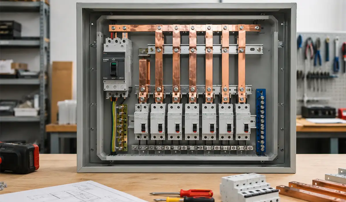
If you are looking for more information about electrical panels, it is recommended not to miss reading this article.
My first generator sizing mistake; confusing service size with actual load
I had fallen into the “200A service = 200A generator” trap.
A 200A single-phase service at 240V has a theoretical maximum of:
- P = V × I
- P = 240V × 200A = 48,000W
- P = 48 kW
That does not mean my house regularly used 48 kW. In reality, most of the time it was far below that.
What I really needed to know was:
- What loads must run during an outage?
- Which loads can be delayed or shed?
- Which loads have high startup current (motors/compressors)?
- Is the house all-electric, or are heating/cooling loads gas-fired?
That changed everything.
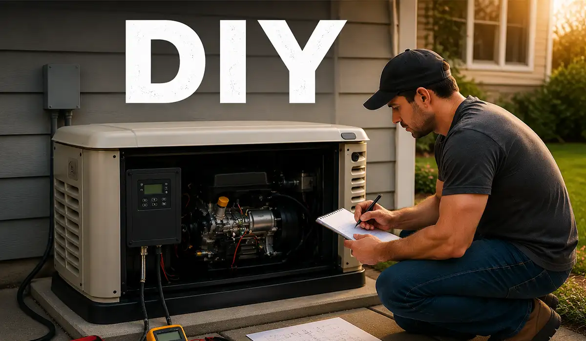
How I did my generator sizing load audit (the part that actually mattered)
I grabbed a notebook, my panel schedule, and a plug-in power meter for some appliances. For fixed loads, I checked nameplates. For a few motor loads, I used a clamp meter while testing on utility power.
I split loads into three categories:
- Critical (must run)
- Comfort (nice to have)
- Luxury/high-demand (usually off during outages)
Here’s the kind of worksheet that saved me from overspending.
My generator sizing worksheet (real-world example)
| Load | Running Watts (approx.) | Starting Watts (approx.) | Priority | Notes |
|---|---|---|---|---|
| Refrigerator | 200–400W | 800–1200W | Critical | Compressor startup spike matters |
| Freezer | 150–350W | 600–1000W | Critical | Often cycles with fridge |
| Boiler/Furnace controls + blower | 400–1200W | 1200–2500W | Critical | Depends on blower motor |
| Lighting (LED circuits) | 100–500W | Same | Critical | Easy to keep low |
| Router + modem + small electronics | 30–100W | Same | Critical | Tiny load, big quality-of-life gain |
| Sump pump | 800–1500W | 2000–4000W | Critical (if needed) | One of my biggest startup loads |
| Microwave | 1000–1500W | Same | Comfort | Short-duration load |
| Washing machine | 400–1000W | 1200–2000W | Comfort | Heater models can draw more |
| Electric water heater | 3000–5500W | Same | High-demand | I planned to keep this off |
| Electric oven/range | 3000–12000W | Same | High-demand | Not realistic for small standby units |
| Central AC (3–5 ton) | 2500–6000W | 5000–12000W+ | Comfort/High-demand | Startup can dominate sizing |
Once I saw this on paper, I realized I didn’t need to power everything at once to have a comfortable outage experience.
That’s where generator sizing became practical instead of theoretical.
If the information related to industrial electrical panel components was interesting and informative to you, researching panel components can be very engaging.
What size generator for 100A, 125A, 150A, and 200A service?
This is the question I kept searching, and the best answer I found (through experience and electricians’ advice) is: it depends on the load profile, not just the service rating.
Still, service size is a useful starting point.
Below is the framework I now use when helping friends think about standby generator sizing.
Practical generator sizing guide by service size (single-phase homes)
| Service Size | Essential Loads Only (managed) | “Most of the House” with Load Management | Near Full Whole-House (depends on heating/cooling) |
|---|---|---|---|
| 100A | 8–14 kW | 12–18 kW | 18–24 kW |
| 125A | 10–16 kW | 14–22 kW | 22–30 kW |
| 150A | 12–18 kW | 18–24 kW | 24–36 kW |
| 200A | 15–22 kW | 20–30 kW | 30–48+ kW |
A few important notes from my project:
- A 100-amp whole-house generator does not automatically mean a 24-kW unit.
- Many 100A homes run very comfortably on 12–18 kW, especially with gas heat, gas water heater, and load management.
- A 200A service home may still work well with 20–26 kW if heavy loads are shed (EV charger, electric range, second AC, electric heat strips, etc.).
- If the home is all-electric (electric heat, electric water heating, multiple AC units), the generator size can climb fast.
For a comprehensive understanding of 200 amp panels, we highly recommend reviewing this article.
The generator sizing moment that changed my buying decision
I originally wanted a generator that could power every circuit exactly as if the utility were never gone.
Then I calculated the cost difference between:
- a large generator,
- bigger fuel demand,
- larger pad/enclosure,
- heavier wiring,
- bigger transfer gear,
- and more noise/maintenance.
That was the second lesson: “whole-house” in marketing often means “whole-house with smart load prioritization,” not “everything at full power simultaneously.”
I ended up designing around a realistic outage lifestyle:
- heat,
- refrigeration,
- lighting,
- pumps,
- internet,
- selected outlets,
- and one comfort load at a time.
That made the system affordable and much more efficient.
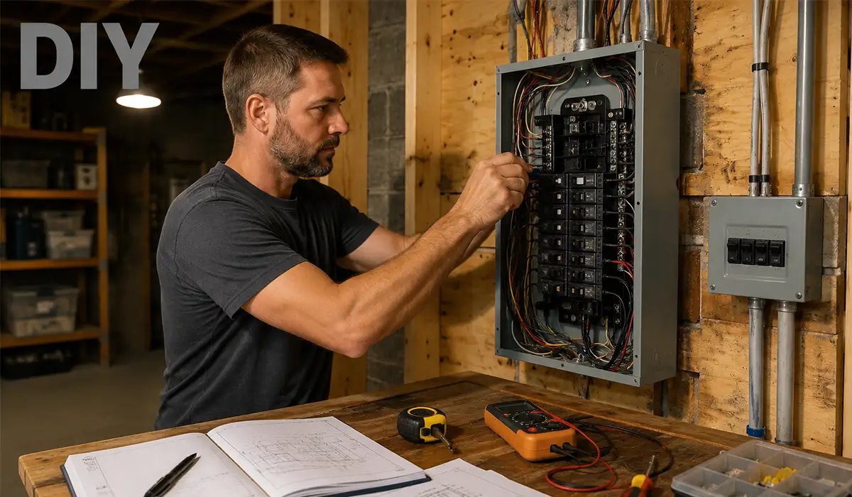
Generator Wiring and Electrical Details I Learned the Hard Way
This is where my “DIY enthusiasm” met electrical reality.
I’m comfortable around electrical equipment, but I’m also careful enough to say this clearly: generator installation touches life safety, utility interconnection rules, grounding/bonding, and code compliance. I did the planning, load calculations, and layout work myself, but I had a licensed electrician review and perform the final connection/inspection-ready work.
That decision probably saved me from at least one expensive mistake.
What size wire for a 100-amp generator?
This was one of the most confusing parts because people online throw around answers without context.
The correct answer is: wire size for a 100A generator depends on multiple factors, including:
- conductor material (copper or aluminum),
- insulation type and temperature rating,
- installation method (conduit, cable assembly, ambient temp),
- termination ratings,
- continuous vs noncontinuous loading assumptions,
- voltage drop (run length),
- local code requirements.
That said, in many common installations, the feeder/output conductors for 100A are often in this range:
- Copper: around #3 AWG Cu (common starting point in many cases)
- Aluminum: around #1 AWG Al (common starting point in many cases)
But here’s where I almost got it wrong:
I focused only on ampacity and ignored run length.
My generator pad location (for noise and exhaust clearance) made the run longer than I initially planned. The electrician recommended upsizing to reduce voltage drop and improve performance during motor starts. That made sense—especially because generator voltage stability matters more when compressors and pumps kick in.
If the information related to wire selection was interesting and informative to you, researching industrial wire can be very engaging.
My practical 100A generator wiring checklist
| Item | What I checked | Why it mattered |
|---|---|---|
| Generator output rating | Nameplate volts/amps/phases | Prevents wrong assumptions |
| Transfer switch rating | 100A / service-entrance vs non-service | Must match system design |
| Conductor material | Copper vs aluminum | Cost, termination type, routing |
| Conductor size | Ampacity + voltage drop | Code + performance |
| Neutral switching | Switched neutral vs solid neutral | Bonding design depends on this |
| Equipment grounding conductor | Sized per OCPD/code | Safety-critical |
| Overcurrent protection | Built-in or external | Required coordination |
| Manufacturer instructions | Lugs, torque, temp ratings | Installation detail often overlooked |
I also learned to respect torque values. Loose terminations in generator circuits can create heat fast, and those problems often show up when the system is under stress—exactly when you need it most.
The transfer switch vs interlock decision in my generator project
I went back and forth between an interlock kit and an automatic transfer switch (ATS).
Both can be valid, but my goals were:
- reliable startup during outages,
- minimal manual steps,
- cleaner family-friendly operation.
So, I leaned toward an ATS setup for standby use.
The “gotcha” I almost missed was the neutral/bonding configuration. Portable generators, inverter generators, and standby generators can have different bonding schemes, and the transfer method changes what is appropriate. That’s not a detail to guess.
This was one of those moments where a professional review wasn’t optional.
If the details you gathered about switchgear performance were interesting and insightful, you may find diving deeper into switchgear performance equally captivating.
Real-world wiring detail I did not expect: placement affects everything
I thought generator placement was mostly about noise and aesthetics.
It wasn’t.
Placement affected:
- cable run length,
- trench/conduit cost,
- voltage drop,
- gas line length (or fuel tank routing),
- service clearances,
- maintenance access,
- and even future replacement options.
I moved the planned location once, and it simplified the electrical run enough to offset part of the installation cost.
That was one of my better decisions.
For a comprehensive understanding of underground conduit, we highly recommend reviewing this article.
Generator Math and Electrical Checks I Used During the Project
I’m a big believer that simple math prevents expensive mistakes.
There were three small calculations/checks that kept coming up while I planned this generator system.
How much current is there in single-phase electricity with 700 watts?
This sounds basic, but it matters when you’re adding small loads and trying not to overload a generator.
The answer depends on voltage and power factor.
For a simple resistive load (power factor ≈ 1), use:
- I = P / V
Example 1: 700W on 230V single-phase
- I = 700 / 230
- I = 3.043… A
- ≈ 3.04 A
Example 2: 700W on 240V single-phase
- I = 700 / 240
- I = 2.916… A
- ≈ 2.92 A
Example 3: 700W on 120V single-phase
- I = 700 / 120
- I = 5.833… A
- ≈ 5.83 A
If the load has a power factor below 1 (common with some electronic/motor loads), current is higher:
- I = P / (V × PF)
For example, 700W at 230V with PF = 0.8:
- I = 700 / (230 × 0.8)
- I = 700 / 184
- I = 3.804… A
- ≈ 3.80 A
This mattered in my planning because a bunch of “small” loads adds up quickly when a generator is also handling the motor starts.
My quick load-addition chart during testing
I made a rough chart while simulating outage loads:
| Test Step | Added Load | Approx. Running Total | What I observed |
|---|---|---|---|
| 1 | Fridge + lights + router | 500–900W | Stable, barely noticeable |
| 2 | Boiler/furnace controls | 1000–1800W | Still stable |
| 3 | Sump pump cycle | 2000–5000W spike | Brief dip, then recovery |
| 4 | Microwave | 3000–6000W total moment | Needed discipline on what runs together |
| 5 | AC compressor test | Big startup event | Confirmed need for load management |
That one table taught me more than hours of generic reading.
How do I know if my house is single phase or 3 phase?
I had this question early on because different generator models are offered in single-phase and three-phase versions, and buying the wrong one is a disaster.
Here’s how I checked it in real life.
1) I checked the utility service and main panel labeling
Most homes are single-phase (often 120/240V split-phase in North America, or single-phase 230V in many other countries).
I looked for labels indicating:
- 1Ø / 1PH / single-phase
- voltage information
- main breaker rating
That gave me the first clue.
2) I counted service conductors (carefully, visually only)
At a high level (without touching anything), I looked at the incoming conductors and how the panel was arranged.
Typical single-phase residential systems generally present as:
- line conductors + neutral (plus grounding system), depending on region and service style.
Three-phase services usually show:
- three-line conductors (L1, L2, L3) plus neutral (in many cases), and the panel equipment is clearly built for three-phase distribution.
3) I looked at the meter/service documentation and utility bill
Some utility documentation explicitly states the service type.
4) I called the utility / electrician to confirm
This was the smartest step because assumptions can be wrong, especially in mixed-use buildings, large homes, workshops, or properties with upgraded services.
In my case, it was a standard single-phase residential service, which simplified generator selection a lot.
If the insights you gained from single-phase systems were intriguing and informative, exploring industrial control systems might be of great interest to you as well.
How much copper is in a generator?
I got curious about this while comparing generator weights and alternator sizes.
The short answer: there is no single fixed amount.
The amount of copper in a generator depends on:
- generator size (kW/kVA),
- alternator design,
- winding design,
- efficiency class,
- stator/rotor construction,
- whether it’s a compact inverter unit vs conventional alternator design,
- manufacturer choices.
I once opened up an old, failed portable generator (out of service, for learning), and I was surprised by how much copper was concentrated in the windings compared with the rest of the unit’s bulk, which was steel, engine mass, and frame.
What I learned:
- Weight alone does not tell you generator quality
- “More copper” can be good in context, but design quality, voltage regulation, winding insulation, engine quality, and support matter more
- Don’t buy a generator based on scrap-value thinking
For standby systems, I cared far more about:
- voltage/frequency stability,
- transient response,
- service support,
- and parts availability.
Since busbars play a crucial role in the production of electrical panels, obtaining more information about busbar systems can be very important and essential.
Whole-House Generator Testing, Setup Refinements, and What I’d Do Differently
The first full-system test felt great… and slightly humbling.
The generator started, transferred correctly, and powered the critical circuits. Then someone in the house used a high-demand appliance at the same time a motor load started, and I watched the system remind me that “theoretical planning” and “real family behavior” are two different things.
That was not a failure. It was a useful test.
My first real-world whole-house generator test routine
After setup, I created a repeatable test routine:
- Simulate outage
- Confirm startup and transfer
- Check voltage/frequency stability
- Add loads in sequence
- Watch for abnormal dips, flicker, or alarms
- Confirm retransfer to utility
- Log what happened
This turned a one-time install into a system I actually trusted.
If you are looking for more information about generator basics, it is recommended not to miss reading this article.
Brands I researched (and why support mattered as much as specs)
I looked at several brands at different price tiers, including:
- Generac
- Kohler
- Cummins
- Champion
- Honda (more for portable/inverter reference)
I noticed something important: spec sheets can look similar, but local dealer support, parts availability, and service response can be wildly different.
For a standby generator, that matters a lot more than people think. The best generator on paper is not the best generator for your house if no one nearby can service it.
The “whole-house” mindset shift that made my setup successful
At the beginning, I wanted a generator that let us behave like nothing had changed.
By the end, I realized a better goal was:
- safe
- reliable
- predictable
- fuel-efficient
- easy for everyone in the house to use
That mindset led to better decisions than simply chasing the biggest kW number.
Further exploration of emergency electrical panels can be found in the following recommended reading.
What I would do differently if I started this generator project again
If I were starting over tomorrow, I would:
- do the load audit first, before looking at generator models
- decide early whether I want true whole-house or managed whole-house
- plan generator placement with electrical + fuel + noise together
- budget for professional review/installation
- test with real household behavior, not ideal conditions
- document a simple “outage load etiquette” list for the family
That last one sounds funny, but it matters. A generator system works best when people know what not to turn on all at once.
Conclusion
This generator project taught me that backup power is less about buying a big machine and more about understanding my electrical system.
The biggest breakthroughs came from simple steps:
- learning the difference between service size and actual demand,
- doing a real load audit,
- respecting wiring details (especially conductor sizing and voltage drop),
- and testing the system like it would actually be used.
If you’re asking questions like:
- “What size generator for 100 amp / 125 amp / 150 amp / 200-amp service?”
- “What size standby generator for 200-amp service?”
- “What size wire for a 100-amp generator?”
- “How do I know if my house is single phase or 3 phase?”
…you’re already asking the right questions.
My best advice is this: start with the loads, not the marketing label. That one decision can save you money, prevent wiring mistakes, and give you a generator setup that actually performs when the lights go out.