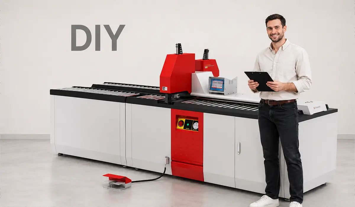

Busbar Basics in My DIY Electrical Panel Project
When I first searched online, I found dozens of versions of the same question: what is a busbar, what is a bus bar, what is a busbar in an electrical panel, what is the function of a busbar, and even what is an electrical bus. I had all of those questions too.
In simple terms, a busbar is a solid conductor, usually copper or aluminum, used to collect and distribute electrical power inside a panel or system.
Instead of running many separate cables from one source to many loads, a busbar gives you a common conductive path that is strong, compact, and easier to organize.
If you are looking for more information about electrical busbars, it is recommended not to miss reading this article.
What a busbar is in an electrical panel?
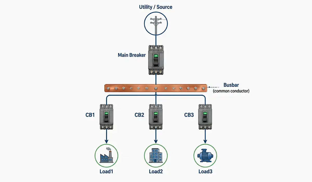
In my workshop panel, the busbar acted like a power highway.
Power entered from the main breaker, and the busbar distributed it to branch breakers and control devices. It made the layout cleaner, reduced cable clutter, and improved consistency.
This is why busbars are common in:
- Distribution panels
- Switchboards
- MCCs (motor control centers)
- UPS systems
- Battery systems
- Industrial control cabinets
If you are looking for more information about busbar panels, it is recommended not to miss reading this article.
What is the function of a busbar really?
Before using one, I thought the purpose of a busbar was only “to carry current.”
That is true, but incomplete.
In practice, the function of a busbar is to:
- Distribute power from one source to multiple circuits
- Reduce wiring complexity
- Improve mechanical reliability compared to loose cable bundles
- Support higher current levels in compact spaces
- Make inspection and maintenance easier
- Improve repeatability in panel manufacturing
That last point mattered a lot when I rebuilt the panel a second time after making mistakes. Busbars made it easier to create a layout I could reproduce.
Why is it called a busbar?
I was curious about this too.
The term bus in electricity refers to a common conductor that serves multiple circuits. The word is widely believed to come from the idea of an “omnibus” or common carrier, meaning it carries many connections together.
So, a busbar is basically a bar-shaped common conductor.
How Do Busbars Work in Electrical Systems?
Once I started tracing current paths in my panel, the concept became simple.
Power enters the panel -> passes through protection/isolation -> reaches the busbar -> branches out to loads.
Here is the mental model I now use:
A busbar works because it has a low-resistance conductive cross-section, so it can carry current efficiently while keeping voltage drop and heat under control, if it is properly sized and installed.
Since busbars play a crucial role in the production of electrical panels, obtaining more information about power distribution can be very important and essential.
Busbar Types and Systems I Compared Before Building
When I started shopping and researching, I realized “busbar” can mean different things depending on context. I wasted time comparing products that were not even meant for the same application.
This section is exactly what I wish someone had explained to me on day one.
Busbar types by material and construction
For a DIY panel, the first decision was material.
I compared copper and aluminum, and also looked at rigid bars vs laminated flexible busbars.
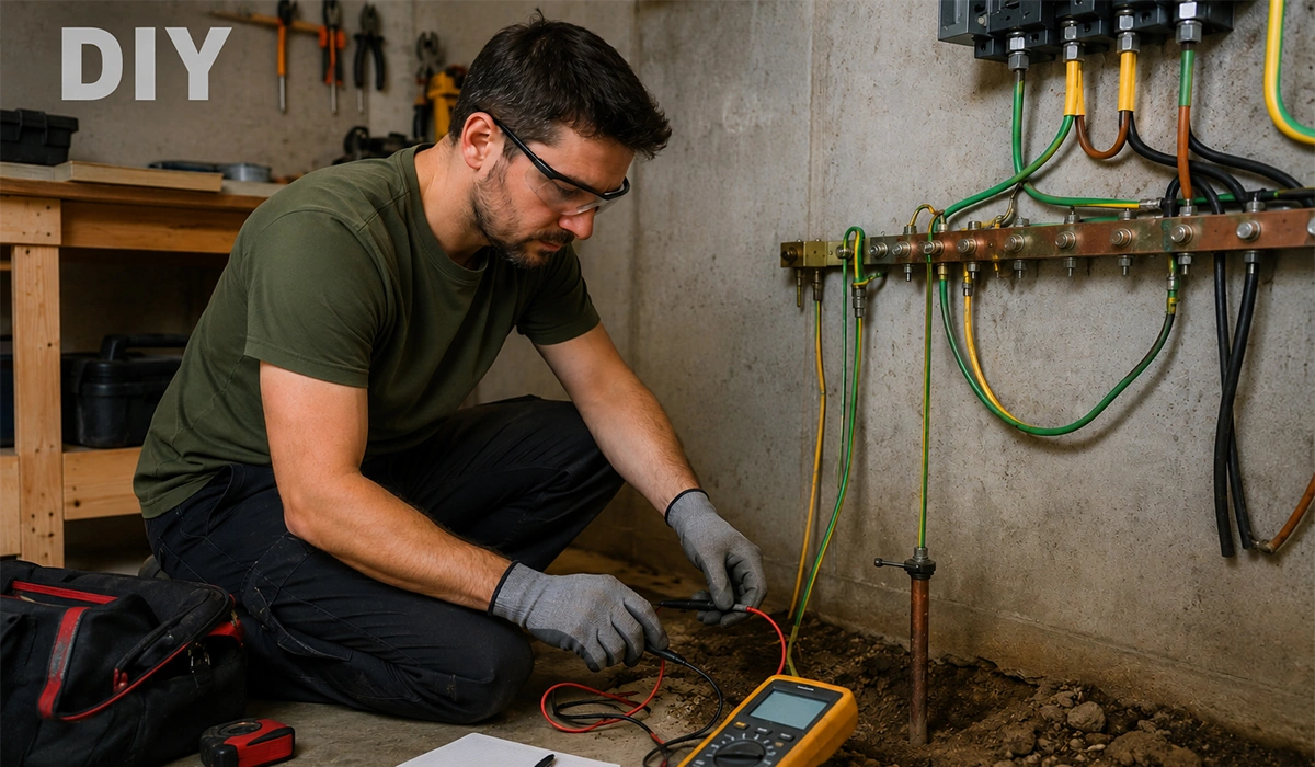
| Step | Change I made | Observation | Measured earth resistance trend |
|---|---|---|---|
| 1 | Initial rod and bonding cleanup | Better continuity, trips still random | High / unstable |
| 2 | Re-terminated corroded clamp and cleaned connections | Improved repeatability | Dropped noticeably |
| 3 | Re-routed PE conductors and separated noisy circuits | Fewer nuisance trips | Similar earth value, better behavior overall |
| 4 | Added second electrode (proper spacing) and improved connections | Much more stable readings | Dropped further |
| 5 | Retested on a different day (drier soil) | Slightly higher than wet-day result | Expected seasonal variation effect |
For my workshop build, I chose a tinned copper flat bar because it was easier to size in a compact panel and I wanted cleaner long-term contact surfaces.
If the information related to flexible busbars was interesting and informative to you, researching flexible busbar types can be very engaging.
Busbar types in power systems and the single busbar system
Then I ran into another topic: busbars in power systems.
This is not only about the bar itself, but also about the arrangement of how power flows in substations and switchgear. I first saw this when reading about redundancy in industrial plants.
Common system arrangements include:
- Single busbar system (simple and economical)
- Sectionalized single busbar (a step up in reliability)
- Double busbar system (more flexibility/redundancy)
- Main and transfer bus (maintenance flexibility)
In a single busbar system, all feeders connect to one common bus. It is simple and cost-effective, but maintenance or faults can affect more circuits.
That concept helped me think better about my own panel layout. I did not build a “power system” style arrangement, but I did split critical and non-critical loads onto separate sections, which made troubleshooting easier.
For a comprehensive understanding of busbar schemes, we highly recommend reviewing this article.
What is a bus coupler in electrical systems?
This term confused me at first.
A bus coupler is a breaker or switching device used to connect two bus sections together. It can allow load transfer, redundancy, or maintenance isolation.
I saw a Schneider and Siemens switchgear example at a facility where one bus section fed production lines and another fed HVAC. The bus coupler allowed flexibility during maintenance.
In a small DIY panel, you usually do not have a formal bus coupler, but the concept is still useful. It teaches you to think in sections, not just in “one big power mess.”
If the information related to busbar arrangements was interesting and informative to you, researching busbar arrangements can be very engaging.
What a busbar trunking system is?
A busbar trunking system (also called busway in many regions) is a prefabricated power distribution system used to carry and distribute power across buildings or industrial spaces.
It is not the same thing as a small flat busbar inside a panel.
Busbar trunking usually comes as enclosed modular sections with tap-off points and insulation systems. I first encountered it in a commercial building retrofit where cable trays were crowded.
Use cases include:
- High-rise buildings
- Data centers
- Factories
- Commercial facilities with long distribution runs
What a bus duct is?
I also searched “what is a bus duct” and assumed it was a different technology.
In many contexts, bus duct refers to enclosed busbar systems used for high-current power distribution, especially between major equipment like transformers and switchgear.
Depending on region and manufacturer terminology, bus duct and busbar trunking may overlap or be used differently.
My practical rule now is:
- Panel busbar = inside a panel/cabinet
- Busbar trunking / busway = modular building distribution
- Bus duct = enclosed high-current interconnection/distribution path
Busbar spelling mistakes and search variations I ran into
I am including this because it genuinely happened during my research.
I searched and saw terms like:
- boost bars
- buzz bars
- busser
- electrical buss
Most of these are spelling mistakes, auto-correct issues, or non-technical variations.
Busbar Design and Sizing for My Panel Build
This is where my project stopped being “fun shopping” and became real engineering.
I made my first design mistake here by sizing only for current and ignoring heat, enclosure conditions, and future expansion. I had to redo the bar layout after a test run showed more heat than I liked.
For a comprehensive understanding of busbar design, we highly recommend reviewing this article.
My busbar sizing workflow
I now use this simple workflow before I cut anything.
| Step | What I Check | Why It Matters |
|---|---|---|
| 1 | Continuous current (A) | Base sizing target |
| 2 | Duty and load diversity | Real operating profile |
| 3 | Material (Cu or Al) | Conductivity and size impact |
| 4 | Temperature rise / enclosure ventilation | Heat management |
| 5 | Fault level / short-circuit withstand | Mechanical and thermal survival |
| 6 | Insulation clearances and creepage | Safety and compliance |
| 7 | Connection points and hole spacing | Real installability |
| 8 | Future expansion margin | Saves rework later |
If you are looking for more information about busbar sizing, it is recommended not to miss reading this article.
How did I calculated busbar size for my panel [practical example]?
I will share the practical method I used, not a substitute for standards-based design.
I estimated my panel demand around 220 A continuous with some motor starting behavior and future headroom. I wanted a copper bar size that would run cooler and allow expansion.
I compared a few options:
| Copper Busbar Size | Cross-sectional Area | Rough Current Density Check (Example) | My Decision |
|---|---|---|---|
| 25 x 5 mm | 125 mm2 | Too close for my comfort in enclosed panel | Rejected |
| 30 x 5 mm | 150 mm2 | Better, but limited expansion | Backup option |
| 40 x 5 mm | 200 mm2 | Comfortable margin and lower heat | Chosen |
| 50 x 5 mm | 250 mm2 | Great electrically, too bulky for panel layout | Rejected |
What I learned the hard way: a busbar that “works on paper” may become annoying in real life if bend radius, support spacing, and breaker alignment are poor.
I also left margin for future loads, and I am glad I did.
If the information related to copper busbar sizing was interesting and informative to you, researching busbar bending can be very engaging.
How must a busbar design account for more than amps?
My early mistake was treating busbar sizing like cable sizing only.
Busbar design also needs attention to:
- Short-circuit forces (electromagnetic force can be significant)
- Support spacing (long unsupported spans can vibrate or deform)
- Thermal expansion
- Joint quality and torque
- Insulation supports and barriers
- Clearance and creepage distances
- Ventilation inside the panel
When I moved one support bracket closer to a breaker connection point, vibration during switching reduced noticeably.
For a comprehensive understanding of busbar clearances, we highly recommend reviewing this article.
Busbar materials and UL surface tracking concerns for high-voltage busbars
One title in your list is especially important: materials meeting UL surface tracking test requirements for high-voltage busbars.
I ran into this while helping review insulation support materials for a project that was beyond basic DIY work.
Here is the practical takeaway I use:
- The busbar conductor may be copper/aluminum, but surface tracking risk is often about the insulation/support material around the energized parts.
- Material selection for high-voltage or high-pollution environments often considers properties like:
- Comparative Tracking Index (CTI)
- Dielectric strength
- Flame resistance
- Moisture resistance
- Creepage design performance
- Common materials used in busbar insulation/support systems can include:
- GPO-3 (glass polyester laminate)
- FR-4 / epoxy glass laminates (depending on application)
- SMC/DMC thermoset compounds
- Engineered thermoplastics with appropriate UL recognition
My most important lesson was this: Do not assume a generic sheet material is compliant just because the base polymer sounds familiar. You need the exact grade, datasheet, UL recognition details, and the actual product/system design review.
For high-voltage busbars, I would always coordinate with the manufacturer, UL file documentation, and the relevant standards team.
UL Certification Process (PDF)
Busbar Manufacturing and Forming in My Workshop
This part was the most satisfying and the most humbling.
I thought cutting and bending the copper bar would be easy. It was not.
Copper is forgiving in some ways, but it will expose sloppy measurement and poor tooling immediately.
How did I cut the copper bar (and what I got wrong first)?
My first attempt was with a basic saw setup and rushed clamping.
The cut wandered slightly, and the burrs were worse than I expected. That one mistake created extra work at the connection surfaces.
After trial and error, my process improved a lot:
- Mark clearly with a scriber and square
- Clamp firmly on both sides if possible
- Use a suitable cutting method (shear, band saw, or proper cutting tool)
- Deburr both faces and edges
- Check width and squareness before drilling
For cleaner results, I later used a shop busbar cutting tool at a local fabricator, and the difference was obvious. The cut quality saved time downstream.
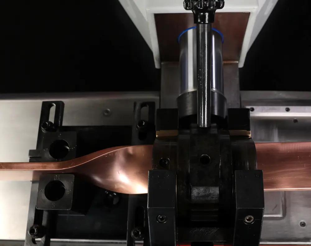
How did I shape copper for panel routing?
Shaping copper is where layout planning matters.
I had one section that needed to pass around a support and line up with a molded-case breaker terminal. My first shape looked okay on the bench but misaligned by a few millimeters inside the panel.
That was enough to create stress at the joint, which I did not want.
Therefore, I changed my routine:
- I made a cardboard template first
- I marked reference centerlines, not only outer edges
- I checked terminal hole centers before bending
- I dry-fitted supports before final shaping
That simple template step probably saved me three reworks.
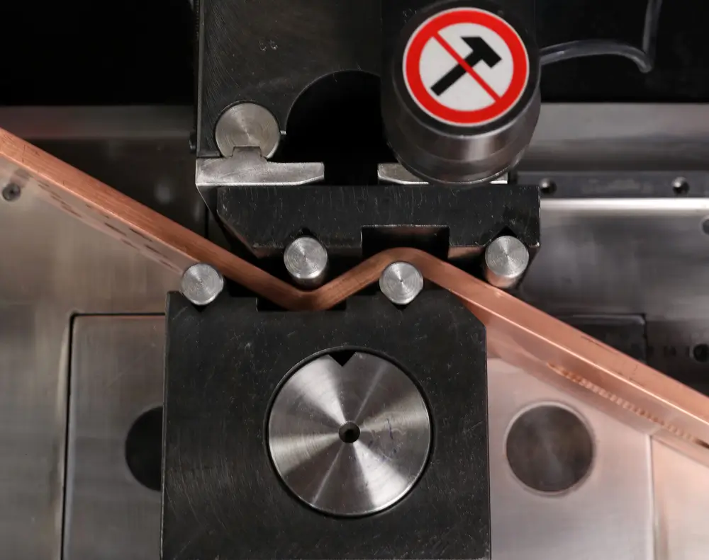
How are single bends in busbars made (my practical understanding)?
This was one of the biggest learning moments.
A clean single bend is not just “push until the angle looks right.”
What matters is:
- Correct die/radius selection
- Consistent bend line marking
- Material thickness
- Springback compensation
- Orientation (keeping twist out)
- Keeping the bend in the same plane
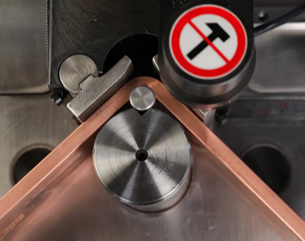
I used a hydraulic busbar bender on a borrowed setup once, and later I tested a smaller manual/hydraulic arrangement. In both cases, I got better results when I:
- Marked the bend centerline carefully
- Aligned the bar against a repeatable stop
- Bent in stages, checking angle incrementally
- Accounted for springback (especially when I wanted precise angles)
- Checked flatness after bending
My first bend overshot the target angle, and trying to “fix” it made the finish worse. Since then, I always approach the final angle gradually.
Manufacturing mistakes that improved my final result
These are the mistakes I personally made and now watch for every time:
| Mistake | What Happened | What I Changed |
|---|---|---|
| Measured from outer edge only | Hole and terminal alignment drifted | Switched to centerline references |
| Ignored burrs after cutting | Poorer contact surface and fit | Deburred immediately after every cut |
| Bent before dry fit | Rework and wasted material | Mock-up fit before final bend |
| Used inconsistent bend reference | Angles varied part to part | Added physical stop and angle checks |
| Rushed drilling sequence | Hole spacing mismatch | Pilot mark, clamp, verify, then drill/punch |
Busbar Installation and Inspection in My Finished Panel
By the time I reached installation, I had already learned that most electrical problems start before power is ever turned on.
A neat busbar install is not only about appearance. It directly affects temperature rise, reliability, and maintenance safety.
Since busbars play a crucial role in the production of electrical panels, obtaining more information about LV panels can be very important and essential.
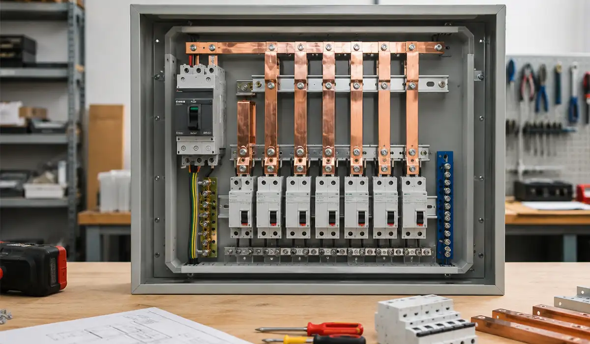
How I installed the busbar in the panel?
I started with the supports and insulation barriers before tightening any final connections.
That helped me avoid forcing the bar into place.
My install sequence looked like this:
- Mount insulators/supports
- Place busbar sections loosely
- Check clearances, alignment, and access to terminals
- Install connection hardware finger-tight
- Verify branch component alignment
- Apply correct torque sequence
- Recheck clearances after torque
- Label sections and phases
- Perform continuity and insulation checks (as applicable)
One practical lesson: if a busbar needs to be “pulled” into position with bolts, something is wrong. Mechanical stress at joints comes back later as heat and looseness.
How I inspected busbar dimensions and build quality
I now treat busbar inspection as a separate task, not an afterthought.
For dimensional checks, I used a caliper, square, angle gauge, and a simple checklist.
| Inspection Item | What I Checked | Tool I Used | Why It Matters |
|---|---|---|---|
| Width and thickness | Matches design | Caliper / micrometer | Current capacity and fit |
| Length | End-to-end accuracy | Steel rule / caliper | Terminal alignment |
| Hole diameter and position | Center spacing and edge distance | Caliper, template | Connection integrity |
| Bend angle | Target angle and consistency | Angle gauge | Fit and stress control |
| Flatness / twist | Bar stays in intended plane | Straight edge / visual check | Joint surface contact |
| Edge finish | Burrs, sharp edges | Visual / glove check | Safety and contact quality |
| Surface condition | Oxidation, scratches, plating damage | Visual | Connection reliability |
After energizing and loading the panel, I also did a temperature check with an IR thermometer and later borrowed a thermal camera. That was one of the best decisions I made.
A connection that looks fine can still run hot.
How I verified how the busbar works under real load?
This was my favorite part of the project because it turned theory into proof.
I ran my workshop loads in stages and monitored:
- Voltage stability
- Connection temperature
- Noise/vibration
- Breaker terminal heating
- Overall panel heat buildup
The busbar itself stayed stable, but one branch connection warmed more than expected. The issue was not busbar size. It was joint preparation and tightening consistency.
That lesson alone justified the whole project.
If the information related to busbar short-circuit performance was interesting and informative to you, researching short circuit withstand can be very engaging.
Busbar Applications and Busbar Material Choices Beyond My DIY Panel
Once I finished my panel, I started noticing busbars everywhere.
Not literally on the street, of course, but in electrical rooms, UPS cabinets, inverters, and factory equipment. Understanding busbars changed how I read electrical systems.
Where are busbars commonly used?
Here are the places I now expect to find them:
- Main low-voltage switchboards
- Distribution boards and panelboards
- Motor control centers
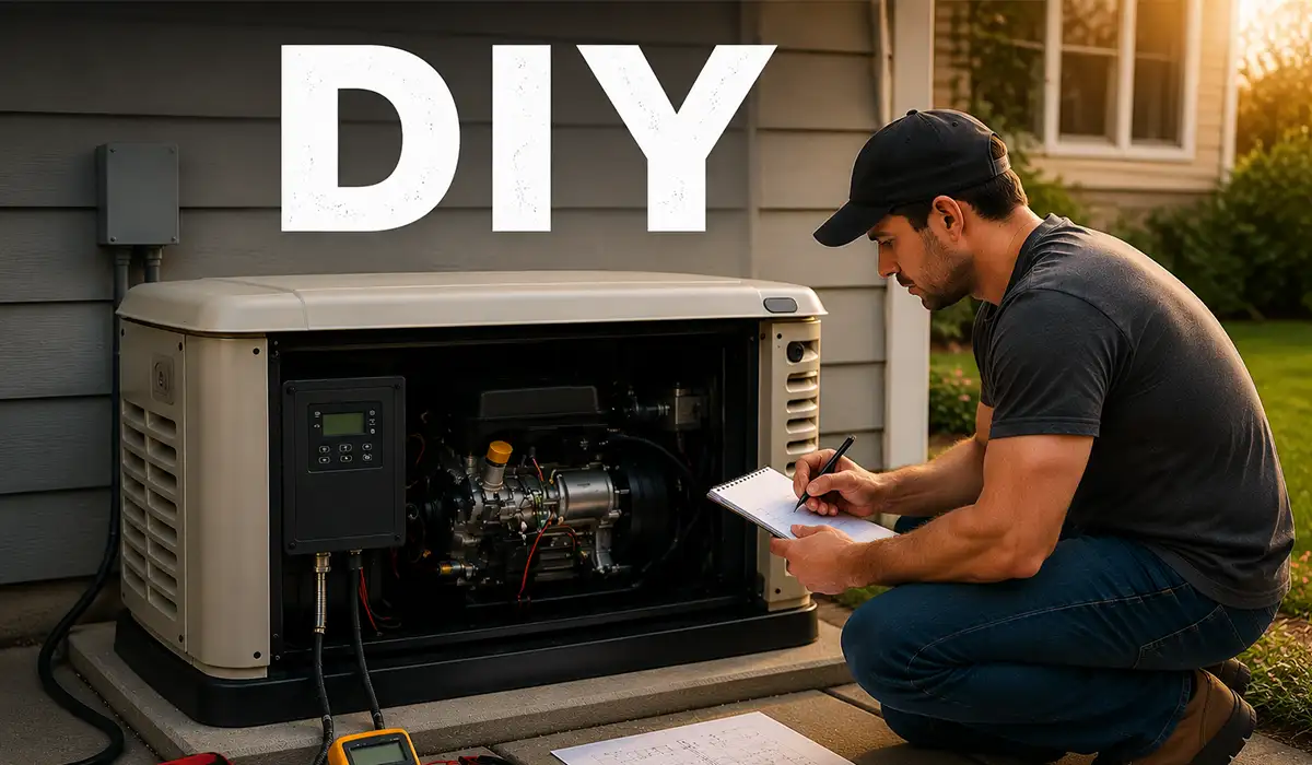
- Generator synchronization panels
- UPS and battery energy storage systems
- Solar inverter combiner/distribution equipment
- EV charging infrastructure
- Transformer to switchgear connections (often via bus duct/busway)
- High-current machine distribution sections
Even when cables are still used, busbars often appear at the high-current distribution points.
For a comprehensive understanding of distribution boards, we highly recommend reviewing this article.
How I approached sustainable busbar sourcing for eco-friendly projects?
I also became more interested in sustainability after seeing how much scrap copper can accumulate during fabrication.
For smaller eco-conscious projects, I now look for suppliers/fabricators that can offer:
- Recycled-content copper or aluminum information
- RoHS / REACH compliance documentation (when relevant) Documentation (PDF)
- Responsible plating and finishing processes
- Scrap return/recycling programs
- ISO 14001-aligned manufacturing practices (if available) Documentation (PDF)
- Local sourcing to reduce transport impact
In one project, a local fabricator agreed to keep and recycle all offcuts and share the weight records. It was a small step, but it made the project cleaner and more intentional.
If the information related to busbar future applications was interesting and informative to you, researching busbar trends can be very engaging.
My quick busbar decision chart for future projects
I keep this simple decision chart in my notebook.
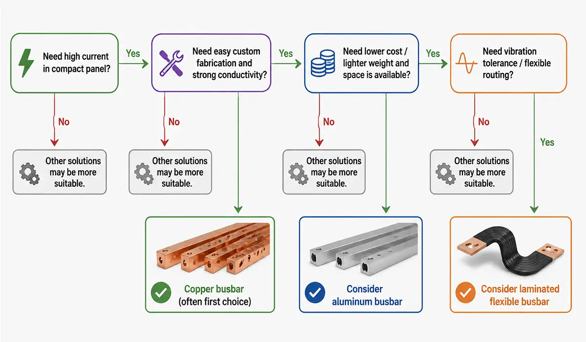
It is not a full engineering method, but it helps me start the right conversation.
For a comprehensive understanding of busbar selection, we highly recommend reviewing this article.
Busbar Conclusion From My DIY Journey
If I had to summarize my busbar journey in one sentence, it would be this: busbars look simple, but good busbar work is a mix of electrical design, mechanical accuracy, and patient execution.
I started with basic questions like “what is a busbar?” and “why not just use cables?” and ended up learning about sizing, heat, short-circuit forces, insulation materials, bend quality, inspection methods, and even system-level concepts like bus couplers and bus duct.
My biggest improvements came from slowing down:
- I stopped rushing measurements.
- I started using templates.
- I treated inspection as part of the build.
- I checked performance under real load.
If you are planning a DIY panel project, busbars can make your design cleaner and more reliable, but only if you respect the details. Start small, stay safe, and verify everything twice.