


Prefer listening? You can play the audio version of the rest of this article below.
Standards & Compliance with IEC 61439 for LV Panels
When I began, my first mistake was searching for parts before I clarified which standard family I was trying to align with.
I was building a low-voltage panel assembly for a real workshop environment, so I needed to understand what the IEC standard for LV panels actually is. That pushed me toward IEC 61439, and that decision changed everything about how I planned the project.
You can review the original source here to verify the technical details.
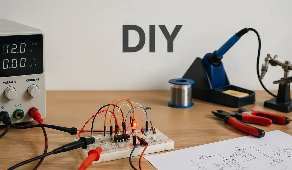
To orient myself, I made this quick planning chart in my notebook:
| Concept | Practical Use | Main Formula |
|---|---|---|
| Ohm’s Law | Load current, resistance checks, voltage checks | V = I × R |
| DC power | Heaters, coils, lamps, DC supplies | P = V × I |
| Single-phase AC power | Small motors and AC loads | P = V × I × cos φ |
| Three-phase AC power | Industrial motors and feeders | P = √3 × VL × IL × cos φ |
| Power factor | kW vs kVA management | PF = P / S |
| Voltage drops | Cable sizing and load voltage | VD% = VD / Vsupply × 100 |
| RMS value | AC ratings and measurements | VRMS = Vpeak / √2 |
Getting started with LV panel compliance requires a clear understanding of the standards that govern switchgear and busbar systems. Knowing where each standard fits within the broader framework helps avoid costly design revisions. For a structured overview, this article on switchgear standards is highly recommended as a starting point.
What is the difference between IEC and IECEx?
Before touching IEC 61439, I had to answer a basic question I should have asked earlier: what is IEC?
IEC stands for the International Electrotechnical Commission, which publishes international standards for electrical, electronic, and related technologies. IEC itself is not a single “standard”; it is the standards organization, and each topic is covered by specific IEC standards (like IEC 61439 for LV assemblies). You can find more background information and related technical notes through this reference link.
That sounds obvious now, but at the time I kept saying “I need the IEC standard,” as if there were only one.
You can download the Introduction to the IECEx System and IECEx Scheme Certification Processes here.
The distinction between IEC and IECEx is one of the most commonly misunderstood areas in electrical compliance. A focused comparison of ATEX and IECEx requirements — including zones and marking obligations — can save significant time during the design phase. This article on ATEX vs IECEx provides a clear and practical comparison.
What is the IEC standard for LV panels?
For low-voltage switchgear and controlgear assemblies, IEC 61439 is the key standard series I kept coming back to.
The IEC Webstore description for IEC 61439-1 explains that Part 1 lays down general definitions, service conditions, construction requirements, technical characteristics, and verification requirements for low-voltage switchgear and controlgear assemblies.
That helped me understand something important: Part 1 is not “the whole answer.” It is the general rulebook.
Understanding IEC 61439 as the governing standard for LV panels is the foundation of any compliant panel build. The design verification process under this standard deserves particular attention, as it defines how conformity is established and documented. This guide on IEC 61439 verification is an essential reference.
What is IEC 61439-2 and what does it cover?
The next thing that clicked for me was the Part 1 + Part 2 relationship.
IEC 61439-2 specifically covers power switchgear and controlgear assemblies (the power distribution type assemblies most people think about when discussing LV panels), while Part 1 provides the general rules used alongside it. The official product pages and standard previews also show that Part 2 is read together with Part 1 in the series structure.
This is where my first redesign happened.
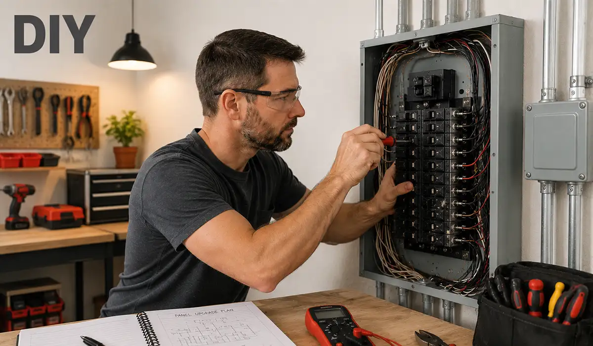
I had originally drawn a cramped layout with the main switch, feeder breakers, contactors, and terminal blocks packed too tightly because I was optimizing for enclosure size. After reading more about assembly standards and seeing how much verification and construction discipline matters, I upsized the enclosure and re-spaced everything.
It felt expensive in the moment, but it saved me later.
Download The standard IEC 61439 in practice guide here.
IEC 61439-2 is closely related to the broader family of assembly standards, and understanding how it compares to regional equivalents such as AS/NZS 61439 can be valuable for engineers working on international projects. This practical guide on AS/NZS vs IEC 61439 clarifies the key differences.
What is the IEC standard for panel testing?
This was the point where I stopped thinking like a hobbyist and started thinking like a panel builder.
I assumed “panel testing” meant insulation resistance, continuity, and maybe a functional run. But in the IEC 61439 world, conformity is tied to a broader verification approach. Industry guidance documents tied to IEC 61439 explain that conformity involves design verification (using methods such as testing, comparison, and assessment, as applicable) and routine verification for each assembly.
That changed how I worked.
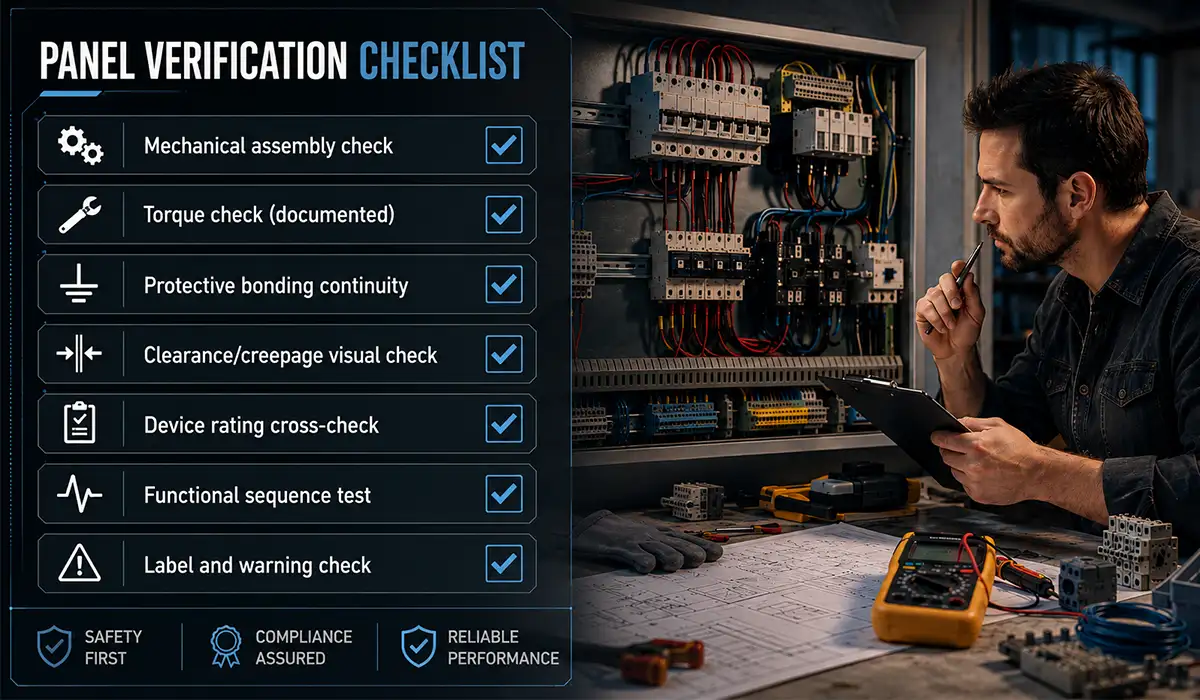
I created a simple verification checklist before wiring the first conductor:
- Mechanical assembly check
- Torque check (documented)
- Protective bonding continuity
- Clearance/creepage visual check
- Device rating cross-check
- Functional sequence test
- Label and warning check
Was it a full certified IEC test program? No.
But it immediately reduced mistakes. I caught two wrong breaker frame assumptions and one mislabeled neutral terminal strip before energizing anything.
Panel testing under IEC standards also intersects with pollution degree and overvoltage category concepts, which directly affect clearance and creepage requirements. Understanding these parameters early in the design process prevents costly rework. This article on pollution degree provides a clear technical explanation.
My first real mistake under IEC thinking
I used a nice enclosure and decent DIN rail parts, but I treated the busbar support spacing casually.
During a dry fit, I noticed my copper bars (I used tinned copper flat bar for one section and bare copper for another prototype) were mechanically solid at rest but had too much flex for my comfort when I simulated cable pull and tightening force.
That was the moment I realized standards are not just about passing a test. They are about building assemblies that survive real handling, real installation, and real fault stress assumptions.
I remade the support arrangement, used proper insulating supports, and added clearer phase identification. It looked less “minimalist” and more industrial, which was exactly the point.
Download the IEC/EN 60079-14: Explosion Protection for Technical Plants here.
Busbar support mistakes are among the most common issues in DIY and small-series panel builds. Compliance in busbar manufacturing goes beyond mechanical support — it covers material, finishing, and assembly discipline. This article on busbar compliance is a valuable resource for anyone building panels with custom busbars.
Standards & Compliance with UL 891 and UL 508A for U.S.-Focused Builds
After I got the IEC side under control, I tried adapting the same design logic for a U.S.-style project concept.
That is where I ran into a very common confusion: switchboards vs industrial control panels, and UL 891 vs UL 508A.
I had mixed them up in my notes more than once.
Here is the comparison table that finally fixed it in my head:
| Topic | UL 891 | UL 508A |
|---|---|---|
| Typical focus | Switchboards | Industrial control panels |
| Scope style | Dead-front switchboards | Industrial control panels for general industrial use |
| Voltage scope (headline) | 1000 V or less | 1000 V or less |
| My use case | Power distribution assembly concept | Control cabinet / machine control panel concept |
Understanding the difference between UL 891 and UL 508A is essential for anyone building or specifying panels for the North American market. A clear breakdown of panelboard, switchboard, and switchgear categories helps prevent misclassification errors. This article on switchboard vs switchgear explains the distinctions in practical terms.
What is UL 891?
UL 891 applies to switchboards nominally rated 1000 V or less and intended for use with the NEC (ANSI/NFPA 70), Canadian code, and Mexican installation standard, and the UL scope explicitly defines the term switchboard here as a dead-front switchboard. It also states exclusions and notes the available short-circuit current coverage up to 200,000 A (with stated conditions).
This was hugely helpful because it corrected my terminology.
I had been calling a compact control enclosure a “switchboard” in one draft BOM. That was wrong for what I was actually building.
Once I separated “distribution switchboard” thinking from “industrial control panel” thinking, my component choices got cleaner.
The complete resource file is available here for offline reading and comparison.
UL 891 is the primary standard for industrial switchboards in the U.S. market, and understanding it in plain language saves significant time during project planning. This plain-English guide on UL 891 switchboard is a practical reference for engineers new to this standard.
What replaced UL 508A?
This question came up because I saw people online talking about revisions and thought UL 508A had been replaced.
It has not been “replaced” in the way many people assume. UL 508A is still active, with revisions and future effective dates managed through UL resources. The UL standards page shows UL 508A as active (Edition 3 with current revision information), and UL Solutions maintains a page for UL 508A future effective dates for requirement changes.
That was a relief, because I almost wasted time hunting for a non-existent “new replacement standard.”
What did matter was understanding revisions and dates, especially if a build is intended for formal compliance or certification.
Download UL 508A Industrial Control Panels here.
UL 508A remains the active standard for industrial control panels in the U.S., and understanding its compliance requirements in detail is critical for panel builders. A focused compliance guide covering the key requirements and common mistakes is available in this article on UL 508A compliance.
My UL-related try-and-error moment
I built one prototype control section with excellent components: Schneider contactors, Phoenix Contact terminals, Eaton breakers, and a clean wire duct layout.
I felt proud until I reviewed it against UL-style thinking and noticed I had not properly organized my documentation around component suitability, SCCR logic, and enclosure labeling discipline.
The hardware looked professional.
The engineering record did not.
That project taught me a painful but useful lesson: neat wiring is not the same thing as compliant panel construction.
The difference between a UL listing and a field evaluation is something every panel builder should understand before starting a compliance-focused project. Choosing the wrong path can add time and cost to certification. This article on UL listing explains both routes clearly.
Standards & Compliance with NEC References in Real Panel Wiring
This was the most practical part of my learning, because NEC questions showed up exactly where mistakes happen: GFCI decisions, overcurrent device locations, and neutral-ground bonding in sub-panels.
I started keeping a “code question” page in my project binder because I was tired of second-guessing myself during wiring.
NEC compliance in panel wiring intersects directly with overcurrent protection methods and device selection. Understanding the available protection approaches helps when designing panel layouts that must meet code requirements. This article on overcurrent protection is a useful reference for this stage of the work.
My on-the-bench troubleshooting flow (NEC-focused)
Symptom -> “Something feels off in layout”
-> Check device location and accessibility (OCPD)
-> Check neutral and ground separation/bonding point
-> Check GFCI requirement by appliance/use case and edition
-> Confirm local adopted NEC edition
-> Rework before energizing
Troubleshooting panel wiring issues efficiently requires the right measuring instruments and a systematic approach. Having reliable electrical measuring devices on the bench speeds up fault-finding significantly. This article on measuring devices covers the essential tools every panel builder should have.
NEC 210.8(D): what does it cover?
This one surprised me because I had older notes.
A practical code summary source explains that in the 2023 NEC, 210.8(D) covers GFCI protection requirements for specific appliances (Class A GFCI), and it lists appliance categories such as dishwashers, clothes dryers, microwave ovens, electric ranges, wall-mounted ovens, and others, while also noting the section changes from earlier NEC editions.
My takeaway was simple: never trust old memory for NEC details.
I had copied a 2020-era assumption into my build notes. If I had followed it blindly, I could have under-specified GFCI protection in a real installation plan.
NEC 210.8(D) GFCI requirements are part of a broader arc flash and protection framework that panel builders must understand. Arc flash label requirements under NFPA 70E and IEEE 1584 are equally important for safe panel design and documentation. This quick reference guide on arc flash labels is a recommended resource.
Where are overcurrent protective devices normally installed?
When I laid out my panel, I initially placed one protective device section behind a removable inner cover that required tools and awkward reach.
That felt fine on the bench, but not after I reviewed accessibility logic.
A practical NEC 240.24 summary highlights that switches containing fuses and circuit breakers are to be readily accessible, and it also notes the exception allowing tool access to overcurrent devices located within listed industrial control panels or similar enclosures (edition-specific context matters).
That pushed me to reorganize the front layout.
I moved operator-facing protective devices to a more accessible position and reserved tool-access-only devices for internal panel arrangements where that approach made sense for the design.
You can visit the official website for more detailed and updated information.
Overcurrent device placement is closely linked to high voltage testing procedures that verify insulation integrity before commissioning. Running proper dielectric and high voltage tests on a completed panel is a critical step before energizing. This article on high voltage testing provides a clear overview of what these tests involve and when they are required.
Neutral bar bonding in sub-panel question (the mistake I almost made)
This was the biggest “I know this… wait, do I?” moment.
In one iteration, I had installed the neutral bar with a bonding screw still in place from a previous enclosure setup. I caught it before energizing, but only because I had gotten more disciplined about neutral/ground checks.
A code-summary explanation of NEC 250.24(A)(5) states that the grounded conductor (neutral) is not to be connected to normally non-current-carrying metal parts, equipment grounding conductors, or reconnected to ground on the load side of the service disconnect, except where otherwise permitted in Article 250. It also emphasizes isolation of grounded conductors downstream of the service disconnect in typical cases.
That single check probably saved me from a dangerous and embarrassing wiring error.
Now, whenever I build or modify a sub-panel section, I physically point to three things before closing the door:
- Neutral bar isolated?
- Ground bar bonded?
- Bonding screw/strap where it belongs for this panel role?
Neutral bar bonding mistakes are closely connected to broader grounding and earthing system design. Understanding the complete earthing system — including the different earthing methods — helps prevent bonding errors at the sub-panel level. This article on grounding earthing system provides the foundational knowledge needed to get this right.
Busbar bonding/grounding NEC question (what I now do every time)
My busbar-related mistake was not about current capacity. It was about fault path thinking.
I once focused too much on ampacity and forgot to validate the bonding path integrity from metal enclosure parts, gland plate, DIN rail bonding jumpers, and ground bar continuity back to the correct grounding point.
After that, I added a mandatory “bond path continuity” test to every build, including door bonding straps and painted-surface scrape points where needed.
This is one of those areas where the panel can look perfect and still be unsafe.
Validating the busbar bonding and grounding path requires reliable earth resistance measurement methods. Knowing which measurement technique to apply in different site conditions improves accuracy and saves time. This article on earth resistance explains the main methods and when to use each one.
Standards & Compliance with CE Marking for Global Electrical Equipment
The moment I started thinking about selling a panel design kit internationally, CE became unavoidable.
At first, I misunderstood CE as a quality badge that someone issues to you.
It is much more specific than that.
The European Commission explains that CE marking on products sold in the EEA signifies the product has been assessed to meet applicable safety, health, and environmental protection requirements, and that manufacturers are responsible for conformity assessment, the technical file, the EU declaration of conformity, and affixing the CE marking where required.
That changed the way I documented prototypes.
To explore the topic in greater depth, review the information available on this website.
CE marking for electrical equipment involves understanding EMC requirements alongside safety directives. Industrial control panels in particular must meet IEC 61000 EMC standards as part of the CE conformity process. This article on EMC requirements explains how these obligations apply in practice.
How to CE / what does CE stand for in electrical?
In day-to-day engineering talk, people often ask “How do I CE this?” What they usually mean is: how do I complete the conformity process for a product that falls under CE-marking legislation?
For my workflow, the practical version became:
- Identify whether the product is in scope of CE marking legislation.
- Identify applicable directives/regulations and harmonized standards.
- Design and test to those requirements.
- Build the technical file.
- Issue the EU Declaration of Conformity.
- Affix CE marking correctly (if applicable).
The EU CE-marking portal also clearly notes two points many people miss: not all products require CE marking, and CE marking does not mean the EU has individually approved the product as “safe.”
That last point was important for me because it stopped me from using sloppy language in product notes.
The CE marking process for industrial control panels has specific requirements that differ from general product compliance. Understanding exactly what is required for control panels — including documentation and testing obligations — is covered in detail in this article on CE marking panels.
My CE-related documentation lesson
I once had a beautifully assembled prototype with clean laser labels, ferrules on every conductor, and a polished front plate.
Then I tried to write the technical documentation package.
I realized I had no structured record of design assumptions, no traceable revision history for the wiring diagram, and no clear risk notes for end users.
That was the day I learned that documentation is not the boring part after the engineering. It is part of the engineering.
CE documentation discipline also applies to IP and NEMA enclosure ratings, which must be correctly specified and verified as part of the technical file. Understanding the differences between IP and NEMA ratings helps ensure the right enclosure is selected and documented. This article on IP vs NEMA ratings is a practical reference for this requirement.
Standards & Compliance with IECEx for Hazardous Area Projects
I did not build an explosive-atmosphere panel in my workshop, but I almost quoted one for a friend in a process-related application before I fully understood what IECEx means.
Thankfully, I paused.
The IECEx Certified Equipment Scheme is an international certification system for equipment used in explosive atmospheres (hazardous areas), involving independent third-party testing/evaluation and ongoing quality system assessment (QARs), with certified equipment listed in the online certificate system.
That is not a “DIY and figure it out later” category.
For the latest available details, check the official page directly.
IECEx certification for hazardous areas is a specialized discipline that sits within a broader electrical standards framework. Having a reliable reference that covers the full range of electrical standards — from LV assemblies to hazardous area equipment — is essential for engineers working across different project types. This electrical standards guide on electrical standards provides a comprehensive overview.
What is IECEx?
In practical terms, I now explain IECEx like this:
If your equipment is intended for hazardous areas, IECEx is a formal conformity framework that helps ensure the equipment and manufacturing process are assessed against relevant Ex standards through approved certification bodies and labs, with traceability and ongoing compliance expectations. (iecex.com)
Once I understood that, I stopped treating hazardous-area requests like standard indoor control panel jobs.
That one mindset shifts probably prevented a very bad business decision.
IECEx is specifically designed for explosive atmosphere applications, and understanding the different types of earthing systems used in these environments is an important part of designing safe installations. This article on earthing systems explains the main configurations and their applications.
My personal rule after learning IECEx
If a project description includes words like “flammable vapor,” “gas zone,” “dust hazard,” or “classified area,” I do not prototype first.
I ask standards questions first.
Standards & Compliance Summary Table from My DIY Journey
By the end of this project, I had a much clearer mental map. This table is the version I wish I had on day one.
| Keyword / Question | My Plain-English Answer | Why It Mattered in My Build |
|---|---|---|
| What is IEC? | Standards body, not one single standard | Stopped me from using vague requirements |
| IEC standard for LV panels? | IEC 61439 series | Guided panel architecture and verification mindset |
| IEC 61439-2 covers what? | Power switchgear/controlgear assemblies | Helped me classify panel type correctly |
| IEC panel testing standard? | Verification approach under IEC 61439 (design + routine concepts) | Forced me to create a checklist before energizing |
| What is UL 891? | UL standard for dead-front switchboards (U.S./NA context) | Prevented me from mislabeling a control panel as a switchboard |
| What replaced UL 508A? | Nothing in that simple sense; UL 508A remains active and revised | Saved time and confusion |
| NEC 210.8(D)? | GFCI for specific appliances (edition-dependent details) | Corrected outdated notes |
| OCPD location question | Accessibility matters under NEC | Improved front layout usability and safety |
| Neutral bonding in sub-panel? | Keep neutral isolated on load side in typical sub-panel cases | Prevented a dangerous bond error |
| How to CE? | Conformity process, technical file, DoC, CE mark if applicable | Forced better documentation habits |
| What is IECEx? | International Ex certification system | Helped me avoid unsafe oversimplification |
Since busbars play a crucial role in the production of electrical panels, obtaining more information about electrical panel types can be very important and essential for anyone designing or building LV assemblies to compliance standards.
Standards & Compliance Conclusion: What This Project Really Taught Me
I started this DIY panel journey chasing a finished product.
I ended up learning process discipline.
The panel I built in the final version was better than the first one in every way: layout, serviceability, labeling, bonding checks, documentation, and future upgrade potential. But the real improvement was in how I think.
Now I do not ask only, “Will this work?”
I also ask:
- Which standard family applies?
- Which edition is adopted locally?
- What must be verified?
- What documentation proves what I built?
- Am I designing for inspection, maintenance, and fault conditions, not just normal operation?
That mindset is what turns a neat DIY project into a safe, credible engineering project.
If you are building your first serious panel, my best advice is simple: slow down at the standards stage. It feels like a delay, but it is actually the fastest path to a cleaner, safer result.
If the information related to standards and compliance was interesting and informative to you, researching RCM marking requirements for the Australian and New Zealand markets could be very engaging. This guide on RCM mark covers the key obligations and how they relate to international standards frameworks.