









Prefer listening? You can play the audio version of the rest of this article below.
Why These Three Terms Are Frequently Confused
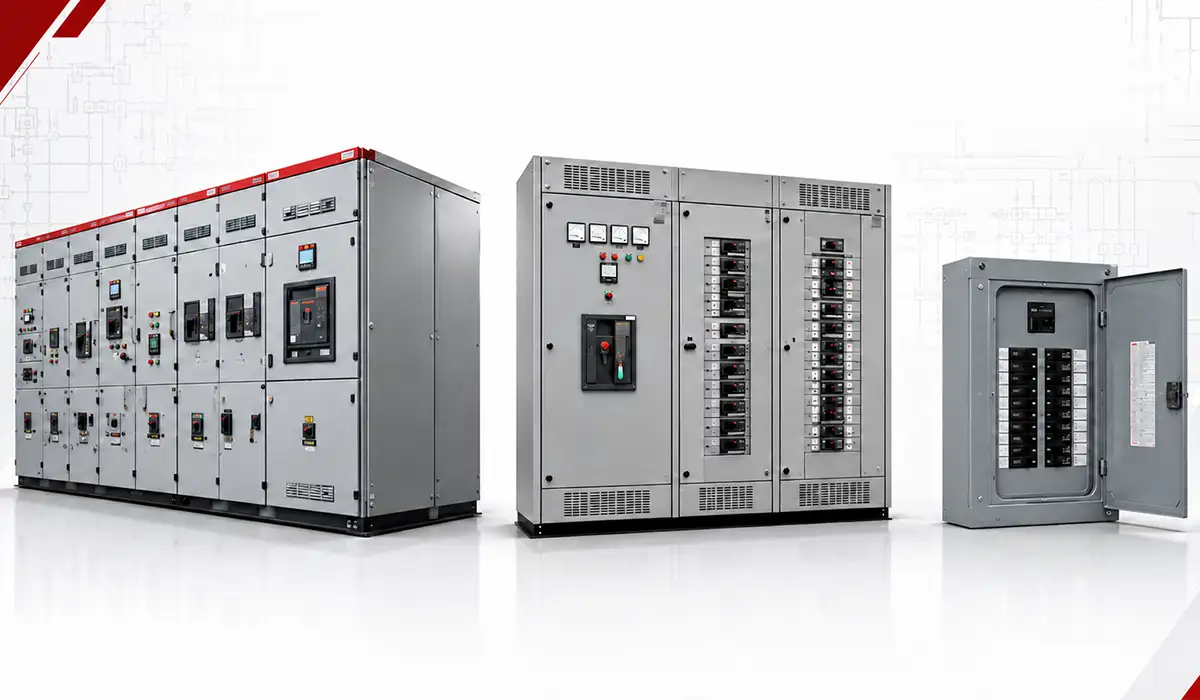
The switchgear vs switchboard vs panelboard question appears so often because all three are metal-enclosed assemblies containing buses (copper or aluminum busbars fabricated with a CNC busbar machine), protective devices, and field wiring terminations.
At drawing level, they can all look like an “electrical panel,” and vendor literature often mixes terms such as distribution board, service equipment, and main distribution equipment. The wider family of electrical panel types adds several more labels to the same pile.
The NEC does not treat them as casual synonyms. Article 408 separates general rules, switchboards and switchgear provisions, and panelboard provisions because construction, access, and intended use differ.
That distinction matters on real projects. A bad label can create the wrong access assumption, the wrong SCCR expectation, or the wrong service-entrance specification.
Definitions — What Each Term Means
In U.S. practice, low-voltage switchgear means a metal-enclosed assembly of switching and interrupting devices with buses and connections. IEEE C37.20.1 specifically covers low-voltage power circuit breaker switchgear with stationary or draw out breakers in individual metal compartments.
A switchboard is a large single panel, structural frame, or assembly of frames carrying switches, overcurrent devices, buses and instruments. UL’s switchboard guide notes that it may be accessible from the rear as well as the front and is not intended for installation in cabinets.
A panelboard is a single panel or group of panel units with buses and automatic overcurrent devices, designed to be placed in a cabinet or cutout box against a wall or partition and accessible only from the front.
The hierarchy is simple: panelboards are downstream branch-distribution devices, switchboards are freestanding distribution assemblies, and switchgear sits at the highest specification level for maintainability and fault-duty performance. That top tier exists for a specific reason, set out in this explanation of the purpose of electrical switchgear.
Master Comparison Table — Switchgear vs Switchboard vs Panelboard
The switchgear vs switchboard vs panelboard comparison becomes much easier once you separate standards, access, mounting style, and fault-duty expectations. (IEEE Standards Association)
| Characteristic | Switchgear | Switchboard | Panelboard |
|---|---|---|---|
| Governing standard (U.S.) | UL 1558 / IEEE C37.20.1 | UL 891 / NEMA PB 2 | UL 67 / NEMA PB 1 |
| Closest IEC analogue | IEC 61439-2 | IEC 61439-2 | IEC 61439-3 for final distribution; sometimes IEC 61439-2 in industrial assemblies |
| NEC Article 408 coverage | Part II + general rules | Part II + general rules | Part III + general rules |
| Typical voltage range | LV up to 1000 V AC standards scope; MV families also exist outside UL 1558 | Up to 600 V AC in typical U.S. low-voltage distribution | Up to 600 V |
| Typical current range | Commonly 1600–10,000 A main bus | Up to 6000 A bus, 5000 A OCPDs in common catalog ranges | Up to 1200 A incoming main |
| Fault-duty / SCCR | High; fully rated high-duty assemblies common | Application-specific; up to 100 kA common in LV catalogs | Application-specific; 10–65 kA common, higher series ratings available |
| Device mounting | Draw out or stationary power breakers | Mostly fixed MCCB/ICCB layouts; some draw out constructions exist | Fixed plug-in or bolt-on branch devices |
These are typical U.S. practice ranges, not universal ceilings. Current rating and SCCR depend heavily on the exact assembly, breaker family, and listed protective-device combination. On the IEC side the equivalent obligations sit with the assembly rather than the devices, as covered in this account of IEC 61439 and UL 891 verification.
The biggest practical split is still fault duty versus access. Switchgear is built around higher-end maintenance and compartmentalization, switchboards balance capacity and cost, and panelboards are optimized for downstream branch circuit distribution.
Switchgear vs Switchboard: What Actually Differs
This is the comparison people ask about most, and the usual answer — “switchgear has drawout breakers” — is not reliable. Some switchboards use drawout molded-case or insulated-case breakers. The real separation is the governing standard and everything that follows from it.
| Characteristic | Switchgear | Switchboard |
|---|---|---|
| Governing standard | UL 1558 / IEEE C37.20.1 | UL 891 / NEMA PB 2 |
| Breaker family | Low-voltage power circuit breakers (LVPCB) | MCCB and ICCB |
| Construction | Each breaker in its own metal compartment | Common enclosure, sectionalised |
| Maintenance | Drawout standard: connected, test, disconnected, removed | Usually fixed; drawout available on some designs |
| Fault duty | Fully rated high-duty assemblies common | Application-specific, up to 100 kA in LV catalogues |
| Typical main bus | 1600–10,000 A | Up to 6000 A |
| Cost position | Highest | Mid-tier |
What compartmentalisation buys you. IEEE C37.20.1 requires breakers in individual metal compartments. That is what lets one breaker be racked out and serviced without de-energising the rest of the lineup, and it is why switchgear is the default in hospitals, data centres and continuous-process plants. The construction philosophy behind that separation is covered in this account of how modern switchgear evolved.
When a switchboard is the correct answer. Where available fault current is moderate, planned outages are acceptable, and budget is a real constraint — which describes most commercial construction. A switchboard is not a compromised switchgear; it is a different tier with a different job.
Switchboard vs Panelboard: Where the Line Sits
Sometimes written panel board, the panelboard is the piece most people picture when they say “electrical panel.” The separation from a switchboard is defined by NEC Article 408, which places switchboards and switchgear in Part II and panelboards in Part III.
| Characteristic | Switchboard | Panelboard |
|---|---|---|
| Governing standard | UL 891 / NEMA PB 2 | UL 67 / NEMA PB 1 |
| NEC Article 408 | Part II | Part III |
| Mounting | Freestanding, floor-mounted | In a cabinet or cutout box, against a wall |
| Access | Front, and often rear | Front only |
| Incoming main | Up to 6000 A bus | Up to 1200 A |
| Distribution level | Service entrance and main distribution | Branch circuits and sub-feeders |
| Typical loads | Feeders to downstream gear | Lighting, receptacles, HVAC branches |
The access difference is the one that decides room layout. A panelboard is accessible only from the front by definition, so it can sit flush against a wall. A switchboard may need rear access, which means clear space behind it as well as in front. Modular systems such as the CUBIC modular switchboard system are built around exactly that front-and-rear access question.
The 1200 A ceiling is the other hard line, and it carries a consequence beyond capacity — see the working-space section below.
Switchgear vs Panelboard: The Two Extremes
These two rarely compete for the same position in a system, which is why the comparison is usually really a question about where you are in the distribution tree.
Switchgear sits at the top: high fault duty, compartmentalised construction, drawout maintenance, freestanding. Panelboards sit at the bottom: wall-mounted, front-access, fixed branch devices, 1200 A maximum.
If a project is genuinely weighing one against the other, one of two things is true:
- The load is small but the fault current is high — a service close to a large transformer. Here the panelboard may simply lack the SCCR, and a switchboard with a suitably rated main is usually the answer rather than switchgear.
- The scope has been misread — a main distribution requirement described as a branch panel. Recheck the single-line before selecting equipment.
In industrial work specifically, the practical difference is maintenance philosophy. A plant that cannot take a full outage to change a breaker needs drawout switchgear. A plant that can schedule downtime does not.
Distribution Switchboards vs Service-Entrance Switchboards
Not every switchboard is service equipment. The distinction is about position relative to the service disconnecting means, and it changes how the assembly is built.
A service-entrance switchboard is fed directly from the utility. It must be specifically built and labelled as suitable for use as service equipment, and it is where the neutral-to-ground bond is made — via the main bonding jumper.
A distribution switchboard sits downstream of the service disconnect. It takes a feeder from the service equipment and distributes it onward to other switchboards, panelboards or motor control centres. It does not carry a service-entrance label, and critically, the grounded (neutral) conductor and the equipment grounding conductor must be kept separate through it. Re-bonding neutral to ground downstream creates parallel neutral current paths through the building steel and conduit.
The physical assembly can look identical. The bonding arrangement, the labelling and the overcurrent protection requirements are not. Both roles are covered in more depth in this guide to industrial electrical switchboards.
Switchgear — Technical Characteristics and Applications
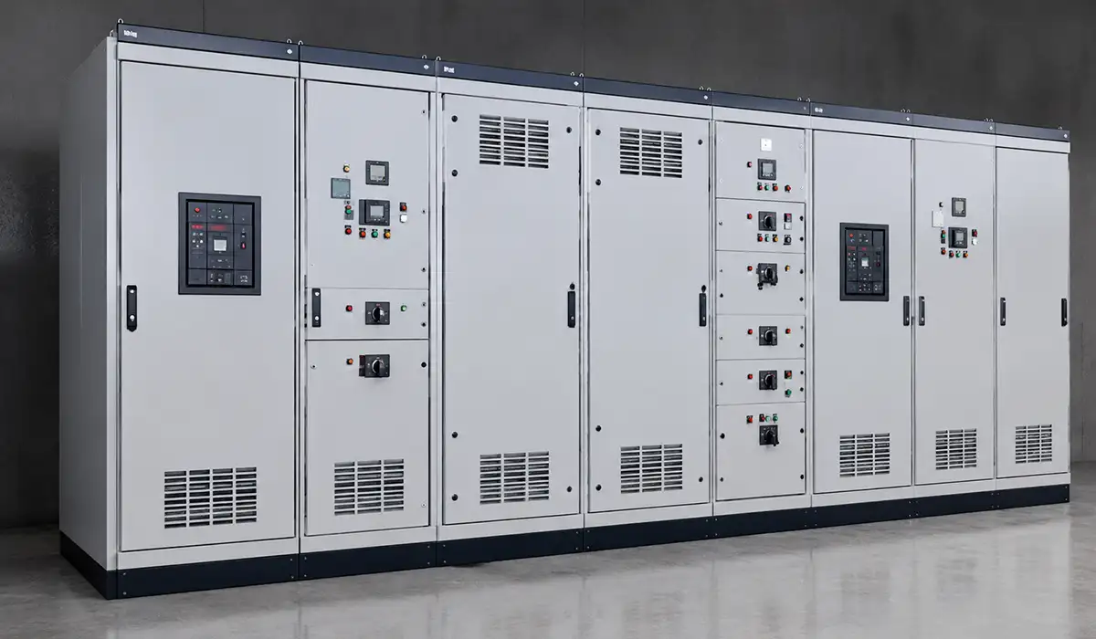
In the switchgear vs switchboard vs panelboard decision, switchgear sits at the highest end of the low-voltage distribution hierarchy. Its defining architecture is compartmentalized power distribution with stationary or drawout power breakers.
IEEE C37.20.1 covers low-voltage switchgear containing stationary or drawout breakers in individual metal compartments. That construction supports higher continuity, cleaner isolation, and more controlled maintenance than wall-mounted downstream gear.
Its electrical role is equally important. Typical ANSI/NEMA low-voltage switchgear is associated with higher main-bus ratings and higher fault-duty expectations than panelboards and most switchboards.
Arc resistance also needs precision. Not every switchgear lineup is arc-resistant, but arc-resistant switchgear is a well-defined tested option under IEEE C37.20.7.
That makes switchgear the usual choice for large service entrances, industrial plants, hospitals, data centers, and other facilities where available fault current is high and outage flexibility matters.
Drawout vs Fixed-Mounted Switchgear
drawout switchgear lets a breaker move through connected, test, disconnected, and removed positions, which reduces outage scope and simplifies maintenance planning.
Fixed-mounted switchgear costs less and can still be appropriate, but servicing one breaker usually requires broader isolation than a drawout design.
Switchboard — Technical Characteristics and Applications
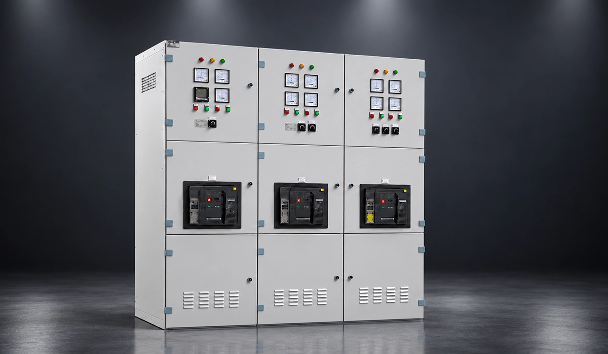
Switchboards occupy the middle tier between high-maintainability switchgear and compact panelboards. In smaller facilities, they may even serve directly as service-entrance equipment from the utility.
Their strength is capacity with practical economy. Common catalogue ratings reach 6000 A bus, with larger commercial distribution sections and more metering options than panelboards offer.
Access is more flexible than many summaries suggest. UL’s guide says switchboards may be rear-accessible as well as front-accessible, and many modern front-access designs remain common.
They also sit at the heart of service-entrance and main-distribution work: offices, hotels, retail centers, multi-tenant buildings, and light-to-medium industrial facilities.
One nuance matters: some switchboards can use draw out molded-case or insulated-case breakers, so the real difference from switchgear is not merely “draw out or not,” but the governing standard, compartmentalization and maintenance philosophy.
Switchboard Metering and Service Entrance Configuration
A service-entrance switchboard must be specifically built and labeled for that duty. Service-entrance duty depends on UL listing and NEC labelling requirements — it is not a property every switchboard has by default.
This is why panelboard vs switchboard which is used for service entrance usually resolves toward switchboards in commercial work: CT metering compartments, utility requirements, and freestanding construction fit the application better.
Panelboard — Technical Characteristics and Applications
Panelboards are the standard equipment for branch circuit distribution. They are designed for installation in a cabinet or cutout box against a wall and are accessible only from the front.
That wall-mounted, front-only format makes them ideal for electrical rooms, corridors, tenant spaces, and local distribution points where depth is limited.
Current capacity is lower than upstream gear. UL 67 panelboards top out at a 1200 A incoming main in standard practice, which is one reason they are not the normal answer for large main distribution.
Their real job is final distribution: lighting, receptacles, HVAC branches, small mechanical loads, and sub-feeders. Whatever the tier, the internal bus carries the same design constraints — geometry, joint quality and clearances — as any other busbar system inside a power switchboard. In other words, they handle panelboard branch circuit distribution rather than utility-scale service functions.
Commercial practice also separates lighting-and-appliance panelboards from power panelboards, even though both still live inside the broader UL 67 panelboard family.
Panelboard vs Load Center — Clarifying a Common Confusion
This topic is often overstated. Eaton notes that, as far as UL and the NEC are concerned, there is no formal code-level difference between a panelboard and a load center.
In practice, “load center” is mainly a residential market term for smaller, lower-cost panelboards. In commercial specifications, “panelboard” remains the correct and safer term to call out.
Fault Current Capacity — The Critical Selection Parameter
If you ask for the difference between switchgear and panelboard fault current capacity, this is the section that decides the answer. Equipment must have a short-circuit rating that matches or exceeds the available fault current at its installed location.
Available fault current is highest closest to the source. The value is recalculated at each point in the system as conductors and busway add impedance downstream from the service point.
That is why equipment class alone is not enough. UL guidance for both switchboards and panelboards make clear that SCCR can depend on the installed breakers, fuses, or listed series combinations.
A useful planning guide is below, but the engineer of record still needs a short-circuit study. Arc-flash analysis is related, but it does not replace the available-fault-current calculation used for equipment selection — and neither replaces correct overcurrent protection and device coordination once the equipment is chosen.
| Available fault current at point of installation | Typical practical choice |
|---|---|
| Up to 10 kA | Panelboard is commonly acceptable |
| 10 kA to 35 kA | Panelboard or switchboard, depending on listed SCCR |
| 35 kA to 100 kA | Switchboard is often the safer default; some special panelboard combinations exist |
| Above 100 kA | Switchgear is usually preferred or required for LV main distribution |
Treat those bands as screening values, not automatic code rules. Panelboards can achieve higher series ratings, and switchboards can vary widely by assembly and protective-device combination.
Working Space and Access Requirements
Equipment class drives room design more than most specifications acknowledge. NEC 110.26 applies to switchgear, switchboards, panelboards and motor control centres alike, but the thresholds bite differently depending on which you choose.
Depth in front of the equipment — Table 110.26(A)(1):
| Nominal voltage to ground | Condition 1 | Condition 2 | Condition 3 |
|---|---|---|---|
| 0–150 V | 3 ft | 3 ft | 3 ft |
| 151–600 V | 3 ft | 3.5 ft | 4 ft |
| 601–1000 V | 3 ft | 4 ft | 5 ft |
Condition 1 is exposed live parts on one side and nothing live or grounded opposite. Condition 2 is live parts on one side, grounded parts opposite. Condition 3 is live parts on both sides.
Width must be 30 in. or the full width of the equipment, whichever is greater. Headroom must be 6 ft 6 in. or the height of the equipment, whichever is greater.
The 1200 A threshold. For equipment rated 1200 amperes or more and over 1.8 m (6 ft) wide containing overcurrent, switching or control devices, there must be one entrance to and egress from the required working space not less than 610 mm (24 in.) wide and 2.0 m (6½ ft) high at each end of the working space. That requirement can be reduced to a single entrance only where unobstructed egress is possible, or where the depths in Table 110.26(A)(1) are doubled.
This is where the panelboard ceiling stops being a capacity number and becomes a building constraint. A 1200 A panelboard stays under the threshold. A 2000 A switchboard over 6 ft wide needs two doors into the electrical room.
The 800 A threshold. Where equipment rated 800 amperes or more is installed and a personnel door for entrance to or egress from the working space is less than 7.6 m (25 ft) from the nearest edge of the working space, that door must open in the direction of egress and be fitted with listed panic hardware or listed fire exit hardware.
Neither rule appears on an equipment datasheet, and both are found late in projects where the room was sized before the gear was selected.
How to Choose Between Switchgear, Switchboard, and Panelboard
For a practical switchgear vs switchboard vs panelboard selection guide, start with fault current, then current rating, then maintenance needs, and only after that consider cost.
Next, define the distribution level. Use panelboards for branch circuits, switchboards for service entrance or main distribution in standard commercial work, and switchgear for higher-duty or mission-critical mains.
Then assess maintenance philosophy. If you need draw out isolation, test position functionality, or better continuity during breaker service, switchgear wins over fixed or simpler downstream equipment.
Room geometry also matters. Panelboards suit shallow wall-mounted installations, while switchboards and switchgear need freestanding floor space, and many rear-access lineups need more depth.
So, when to use switchgear vs switchboard vs panelboard is usually straightforward: panelboards for final distribution, switchboards for economical mains, and switchgear where fault duty, safety options, and maintainability are the governing constraints.
Conclusion
Choosing between switchgear, switchboard, and panelboard is not just a matter of terminology. Each equipment type serves a different role in the electrical distribution system and is defined by clear standards, rating limits, access requirements, and application boundaries.
Switchgear is the highest-specification option, used where fault current is high, maintenance flexibility is critical, and system reliability carries the most weight. Switchboards occupy the middle ground, offering strong service entrance and main distribution capability for many commercial and industrial buildings at a lower cost than switchgear. Panelboards sit downstream, providing practical and compact branch circuit distribution for lighting, receptacles, HVAC, and other end loads.
In most projects, the right choice comes down to five questions: What is the available fault current? What current rating is required? How much maintenance access is needed? How much installation space is available? What budget remains after the technical requirements are met? When those questions are answered in the right order, the selection becomes much clearer.
For most buildings, panelboards handle branch distribution, switchboards support service entrance and main distribution, and switchgear is reserved for higher-duty, higher-risk, or mission-critical applications where performance and maintainability matter most.



Rate this article
Choose a rating from 1 to 5 stars.
3.0 out of 5 — 1 vote