





.svg)

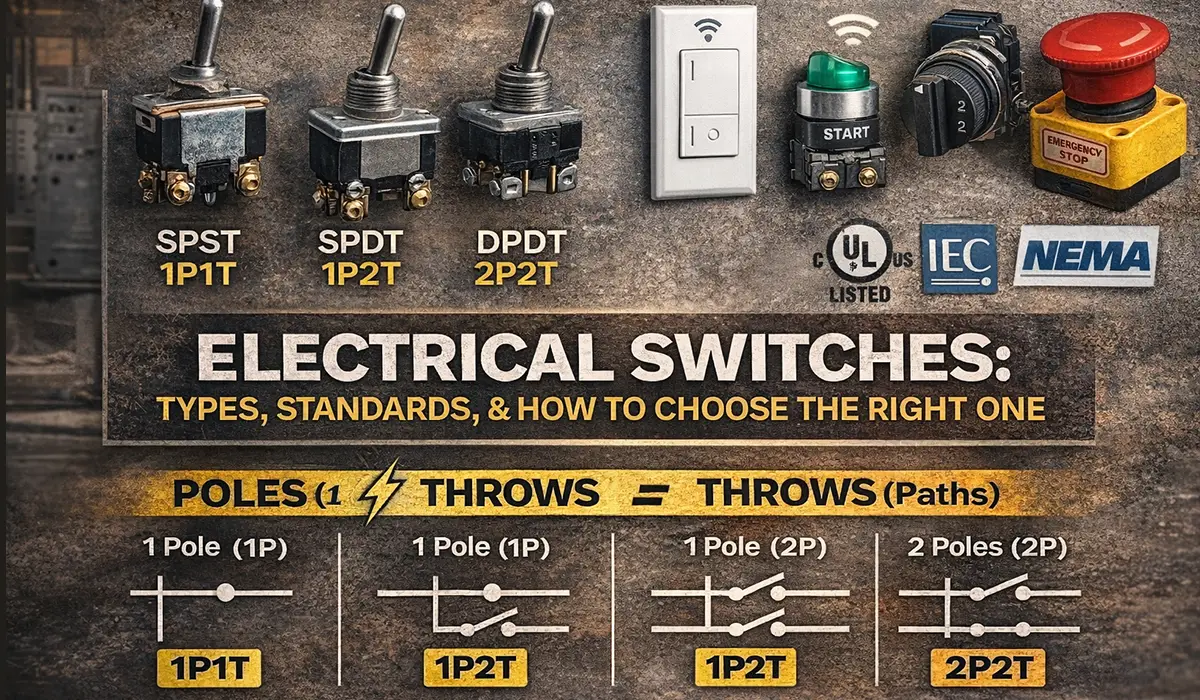





What Is an Electrical Switch? Definition and Working Principle
An electrical switch is a mechanical device that opens or closes a circuit to control the flow of current. When the contacts are open, the circuit is broken and no current flows. When the contacts are closed, current flows to the load. This make-and-break action is the whole function of the device.
Every switch has four basic parts. The actuator is what the operator presses, flips or turns. The contacts are the conductive surfaces that make and break the circuit, usually silver or a silver alloy because these keep low resistance even after surface oxidation. The terminals are where conductors land. The housing holds everything in alignment and protects the live parts.
Two terms describe every switch you will ever specify: pole and throw. They matter far more than whether the device is a toggle, a rocker or a rotary knob, because they define how many circuits the switch controls and how many positions it can select. The same two terms decide how the device is wired alongside the other industrial electrical panel components sharing an assembly.
Poles and Throws Explained: SPST, SPDT, DPST and DPDT
Poles tell you how many separate circuits the switch controls. Throws tell you how many output positions each pole can select. A single-pole switch breaks one conductor. A double-pole switch breaks two conductors at the same time, using one handle.
One point causes constant confusion: a 3-way switch is electrically an SPDT, and a 4-way switch is a crossover device built from a DPDT arrangement. They are wiring configurations, not new pole-and-throw families. Under IEC and British naming the same devices are called two-way and intermediate switches.
| Switch Type | Description |
|---|---|
| SPST | Single Pole Single Throw — simple ON/OFF, one circuit, one path |
| SPDT | Single Pole Double Throw — one circuit, selects between two output paths (changeover) |
| DPST | Double Pole Single Throw — two circuits switched together, each with one path |
| DPDT | Double Pole Double Throw — two SPDTs ganged, two circuits each with two paths |
| 3-Way (IEC: two-way) | An SPDT used in pairs to control one fixture from two locations, linked by traveler wires |
| 4-Way (IEC: intermediate) | A crossover switch inserted between two 3-way switches to add further control points |
Electrical Switching: What Happens When Contacts Make and Break
Electrical switching is the act of making or breaking a circuit under defined conditions. The rated current printed on a switch tells you what it can carry. It does not tell you what it can switch, and that difference is where most selection errors begin.
Two separate duties apply. Making capacity is the stress when contacts close onto a live circuit — an induction motor can draw six to eight times its running current at the moment of closing. Breaking capacity is the stress when contacts open a live circuit, where an arc forms across the separating gap and must be extinguished. A resistive heater and a motor can draw the same running current while behaving completely differently at both moments.
This is why load type drives selection more than current alone. Resistive loads switch cleanly. Inductive loads (motors, contactor coils, transformers) resist a sudden change in current and sustain longer arcs. Capacitive loads produce high inrush at closing. DC is the hardest case of all, because there is no natural current zero to help the arc extinguish — a switch rated 250 V AC may be rated only 30 V DC.
Types of Electrical Switches (By Operation & Use Case)
By mechanism, common families include toggle, rocker, pushbutton, rotary/selector, and slide switches. The physical interface affects ergonomics, accidental activation risk, and whether operation is maintained (stays in position) or momentary (returns when released).
By application, you will see lighting switches (wall control), limit switches (machine position feedback), selector switches (mode selection), and emergency stop devices (safety function). In industry, the “type” is often less important than the rating and duty the switch must survive.
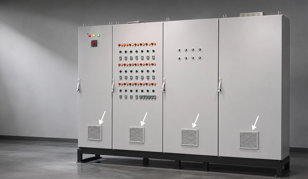
By environment, the switch enclosure matters: dust, wash-down, oils, vibration, and outdoor exposure push you toward sealed designs and clear IP requirements. IP ratings are defined under IEC 60529. Enclosure choice is also driven by the assembly itself, since the different types of electrical panels impose different sealing, mounting and access constraints.
Residential Electrical Switches: One-Way, Two-Way, 3-Way and 4-Way
Residential switching covers one-way (single-pole), two-way (3-way), intermediate (4-way) and double-pole devices, plus dimmers, timers and occupancy sensors. Multi-way switching adds control points, not capacity — a 3-way pair does not carry more current than a single-pole switch. These are also the circuits where arc fault breakers are increasingly required upstream of the switching devices.
The governing standard is IEC 60669-1. It applies to manually operated general purpose switches, AC only, with a rated voltage not exceeding 440 V and a rated current not exceeding 63 A, for household and similar fixed installations, indoors or outdoors. Where screwless or insulation-piercing terminals are used, the rated current is limited to 16 A. In UL-based markets the equivalent is UL 20 for general-use snap switches.
The practical limit to watch is motor duty: household-rated switches carry a very restricted motor rating compared with their resistive rating, so a 16 A wall switch is not a fan or pump controller.
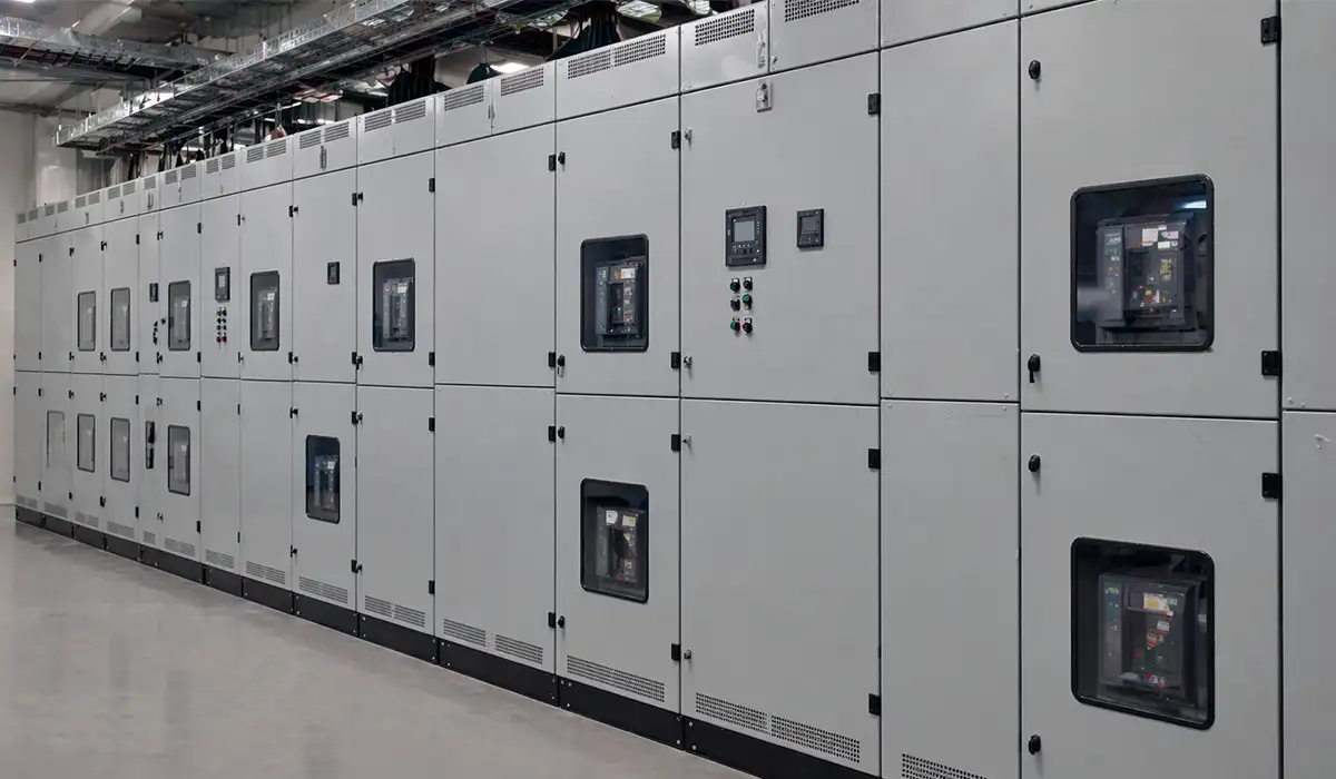
Industrial Electrical Switches: Types Used in Panels and Switchgear
Industrial electrical switches split into two families that are governed by different standards, and mixing them up is the most expensive mistake in panel design.
Power switching devices carry and break the main load current. These are switch-disconnectors, isolators, changeover switches and fuse-combination units, and they fall under IEC 60947-3. Control circuit devices switch signals to coils, relays and PLC inputs, not the load itself. These are pushbuttons, selector switches, limit switches and E-stops, covered by IEC 60947-5-1, with IEC 60947-5-5 applying specifically to emergency stop devices with mechanical latching.
A control-rated device will not survive main-circuit duty, and a power-rated isolator is not a substitute for a properly rated control station. Both families have moved a long way from the knife switches of early distribution equipment, a shift traced in the evolution of modern switchgear.
Industrial Electrical Switch Types at a Glance
| Device | Function | Governing Standard |
|---|---|---|
| Switch-disconnector | Makes and breaks load current, and provides isolation for maintenance | IEC 60947-3 |
| Disconnector (isolator) | Isolation only — must not be operated on load | IEC 60947-3 |
| Fuse-combination unit | Switching plus fuse protection in one device, common on outgoing ways | IEC 60947-3 |
| Changeover switch | Selects between two supplies, e.g. mains and generator | IEC 60947-3 |
| Pushbutton (START/STOP) | Momentary control command to a coil or PLC input | IEC 60947-5-1 |
| Selector switch | Maintained mode selection, e.g. Local/Off/Remote | IEC 60947-5-1 |
| Limit / position switch | Reports mechanical position back to the control system | IEC 60947-5-1 |
| Emergency stop device | Latching stop command with positive opening action | IEC 60947-5-5 |
Switch, Disconnector or Switch-Disconnector?
These three terms are used loosely in catalogues and they are not interchangeable.
A disconnector exists to create a safe, verifiable isolation gap for maintenance. It provides only the isolation function and must not be operated under load. A switch can make and break current, but does not by itself guarantee isolation. A switch-disconnector does both — it combines load breaking and isolation, so it can be operated on a live circuit.
For any device relied on for isolation, look for positive opening operation. This means the contacts are mechanically linked to the handle so they will open even if the contacts have welded together — the property that makes lockout/tagout trustworthy rather than hopeful. A padlockable handle without positive opening gives you a padlock, not isolation.
Utilization Categories: AC-21, AC-22 and AC-23
A utilization category is a performance class, not another current rating. It states the kind of load the device is built to make and break.
| Category | Duty | Typical Application |
|---|---|---|
| AC-20 | Connecting and disconnecting with no load current | Isolation of a de-energised circuit |
| AC-21 | Resistive loads, including moderate overloads | Lighting and heating circuits |
| AC-22 | Mixed resistive and inductive loads, including moderate overloads | Incoming supply to a distribution board |
| AC-23 | Motor loads and other highly inductive loads | Motor outgoing ways in industrial plant |
These categories are defined in IEC 60947-3, alongside the control-circuit categories such as AC-15 for AC electromagnetic loads and DC-13 for DC electromagnets under IEC 60947-5-1. Equivalent DC categories (DC-20 to DC-23) apply to DC circuits and must never be read across from the AC figures.
The selection rule is simple: read the category-specific current, not the headline current. A device that looks generous on the nameplate can be badly undersized once the correct category is applied, and the failure mode is contact erosion, overheating and eventually a welded pole.
Smart Electrical Switches: Neutral Wire, Ecosystems and Trade-Offs
A smart light switch adds electronics and communications (often Wi-Fi, Zigbee, Z-Wave, Thread) so the switch can be controlled by apps, schedules, scenes, or voice assistants. The advantage is keeping normal wall control while gaining the convenience of automation.
The wiring detail that trips people up: many smart switches need continuous power, which is why a neutral wire is often required. Some products are designed for no-neutral installations, but they may need specific load conditions or a bypass/adapter depending on the design.
Use a smart switch vs smart bulb based on what you want to control: switches are better for whole circuits and consistent wall behavior; bulbs are better for color scenes and per-lamp control when the wall switch stays ON.
On the ecosystem side, the market is converging on Matter, with Thread and Wi-Fi as the usual transports, which reduces the lock-in problem that made early smart switches risky to specify. One caution for commercial work: a smart switch is a functional control device, not an isolation device. It does not replace a disconnector, and maintenance isolation must still come from a device rated for it.
Electrical Switch Standards: Which IEC and UL Documents Apply
Compliance works in layers, and each layer has its own document. Confusing the device standard with the assembly standard is a common cause of failed verification.
| Layer | IEC | UL |
|---|---|---|
| Household / General-use Switch | IEC 60669-1 | UL 20 |
| Power Switching Device (LV) | IEC 60947-3 | UL 508 |
| Control Circuit Device | IEC 60947-5-1 (E-stops: IEC 60947-5-5) | UL 508 |
| Complete Assembly / Panel | IEC 61439 Series | UL 508A |
| Enclosure Protection | IEC 60529 (IP) | NEMA Type Ratings |
The distinction matters in practice. UL 20 covers general-purpose applications and states that it does not cover anything covered by UL 508, which is the industrial standard. A switch listed to UL 20 is not automatically acceptable inside a UL 508A panel.
On the IEC side, IEC 61439 governs the assembly and its verification — temperature rise, short-circuit withstand, clearances and documentation. Fitting compliant devices does not make the assembly compliant. The assembly is verified as a whole. The same layered logic applies when specifying industrial electrical switchboards, where the devices and the assembly are approved on separate routes.
Selecting to a Standard: IEC vs UL Considerations
Decide the destination market before you select components, not after. The two systems differ in more than paperwork: IEC verifies the assembly against IEC 61439 with defined test or comparison routes, while the UL approach builds the panel to UL 508A construction rules using listed or recognised components under an established procedure.
Retro-fitting compliance is expensive. A panel built with IEC-only components and then asked to satisfy a UL 508A shop is usually a rebuild, not a paperwork exercise.
How to Choose the Right Electrical Switch: A 6-Step Method
- Define the circuit. System voltage, AC or DC, number of poles to break, and whether the neutral must be switched.
- Classify the load. Resistive, mixed or motor. This sets the utilization category before you look at any current figure.
- Read the category-specific current. Take Ie for your category, not the headline rating.
- Decide if isolation is required. If maintenance staff will work downstream, you need a disconnector or switch-disconnector with positive opening and a lockable handle.
- Match the environment. IP rating to IEC 60529, plus separate checks for vibration, ambient temperature and chemical exposure. Derate for high ambient — panel internal temperature, not room temperature, is the number that matters.
- Check endurance. Mechanical endurance (operations with no load) and electrical endurance (operations at rated duty) are different figures. Switching close to rating shortens electrical life sharply.
Quick Selection Guide by Application
| Application | What to Specify |
|---|---|
| Stairwell or corridor lighting | Two-way (3-way) pair, intermediate switch for a third point |
| Motor outgoing way | AC-23 rated switch-disconnector, lockable, positive opening |
| Distribution board incomer | AC-22 rated switch-disconnector sized to the board rating |
| Wash-down or food processing | Sealed IP65/IP69K device, stainless or sealed polymer actuator |
| Machine START/STOP station | IEC 60947-5-1 pushbuttons; NC contact for STOP, fail-safe |
| Emergency stop | IEC 60947-5-5 latching device with direct opening action |
What Is a Switch Leg? Switch Leg vs Switch Loop Explained
A switch leg is the switched hot conductor that runs from a switch to the load it controls. It is dead when the switch is open and live when the switch is closed. It is sometimes called the switched hot or the load wire.
A switch loop is a different arrangement, and the two are frequently confused. When power arrives at the switch box first, the switched hot run from the switch to the light is the switch leg. When power arrives at the light box first, the two conductors run down to the switch and back are the switch loop. The direction the supply enters is what distinguishes them.
This matters for smart switches. A switch loop wired with two conductors brings no neutral into the switch box, which is exactly the situation where a smart switch will not have the continuous supply it needs. Conductor sizing and insulation type matter here too, which is covered in this guide to choosing the right wire for industrial installations.
| Term | Function and Direction of Flow |
|---|---|
| Line (Hot) | Constant supply from the panel — Panel → Switch |
| Load (Switch Leg) | Carries power to the load only when the switch is closed — Switch → Light |
| Traveler | Connects two switches in a multi-way arrangement — Switch ↔ Switch |
| Neutral | Return path completing the circuit — Light → Panel |
Traveler Wires and Multi-Way Control
Multi-way switching relies on traveler conductors that connect only the switches to each other. Think of them as two parallel tracks: each switch selects which track is live, so flipping either switch changes which path is complete. Adding an intermediate (4-way) switch between the pair crosses the travelers over, allowing a third or fourth control point without changing the outer switches.
Safety Note
Switching interrupts the line conductor, never the neutral. Before any work: isolate, verify absence of voltage with a proven tester, and lock off. This section explains how the circuits work — it is not an installation instruction. Work on panels and fixed installations should be carried out by a licensed electrician under the applicable national wiring rules.
Maintenance, Reliability & Safety
Reliability is mostly boring discipline: inspect for heat discoloration, loose terminations, cracked housings, contamination ingress, and signs of arcing. Torque checks and periodic inspection are common maintenance recommendations in motor control and panel literature. Contact stress is made worse by supply distortion, which is where harmonic filters reduce the thermal load carried by switches and the rest of the panel.
In energized industrial environments, arc flash risk is real. Mitigation strategies include design and settings choices that reduce incident energy, plus maintenance-oriented approaches like energy-reducing methods and operational practices aligned with NFPA 70E principles. Enclosure choice carries much of this burden, and Rittal electrical panels and enclosures show how sealing and thermal management protect switches in harsh environments.
When in doubt, prioritize: correct ratings, correct environment protection, and correct compliance pathway. A cheap switch that fails early is not “cost-effective” — it is just expensive later.
Conclusion
Choosing an electrical switch comes down to three questions asked in order: what is the load, does this device need to provide isolation, and which standard applies in the destination market. Current rating alone answers none of them. A device selected on nameplate current without checking its utilization category is the most common reason contacts overheat and weld in service.
For panel builders, the switch is only one part of a verified assembly. Busbar geometry, joint quality and clearances carry the same weight, and the assembly is what gets tested — not the components inside it. Explore PAYAPRESS CNC busbar fabrication machines for busbar processing that supports IEC 61439 verification.



Rate this article
Choose a rating from 1 to 5 stars.
No ratings yet