






If you’d rather listen than read, feel free to play the audio file below for the rest of this article.
What Is an Industrial Capacitor Bank?
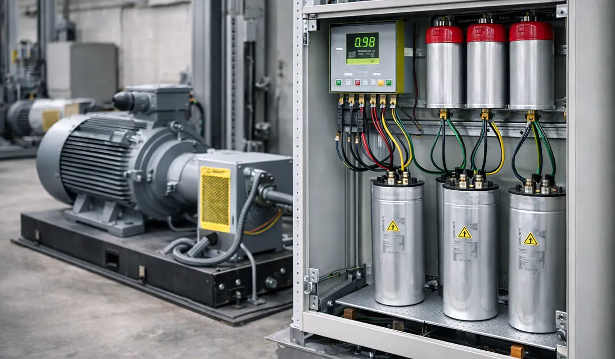
An industrial capacitor bank is an assembly of power capacitors connected in parallel with a plant’s supply to generate reactive power locally, instead of drawing it from the utility. It is the standard method of power factor correction in factories, process plants and commercial buildings.
The principle is straightforward. Inductive loads — motors, transformers, welding sets, induction heaters — draw two components of current. Active current does work. Reactive current magnetises iron and does no useful work, but it still flows through every cable, busbar, breaker and transformer between the load and the utility. A capacitor bank supplies that reactive current at the point of use, so the upstream network only has to carry the active component.
The main uses of an industrial capacitor bank:
- Correcting plant power factor to the target set by the tariff, commonly 0.95 or above
- Releasing transformer and cable capacity that reactive current was consuming
- Stabilising voltage at the end of long feeders
- Reducing I²R losses across the distribution system
A bank is described by three numbers: its kVAR rating (how much reactive power it supplies), its rated voltage, and its step arrangement (how the total kVAR is divided into switchable blocks).
Electricity Costs and Reactive Power Penalties
Failure to use capacitor banks in industrial electrical systems can lead to increased electricity costs and heavy penalties. When the power factor is low, there is an excess consumption of reactive power, which not only increases energy losses in transmission lines and equipment but may also result in penalties imposed by power companies for unnecessary reactive power consumption. These penalties are typically added as extra charges on the electricity bill. Installing a capacitor bank can effectively address these issues and reduce extra costs.
The financial impact of low power factor is often underestimated. Beyond direct penalty charges, a poor power factor forces the upstream network — including the utility transformer, main cables, and switchgear — to carry a higher apparent current than the active load alone would require. This means that the existing electrical infrastructure is being consumed at a faster rate, shortening maintenance cycles and potentially requiring earlier capital replacement. A properly sized capacitor bank eliminates this hidden cost by reducing the reactive component of current and allowing the full capacity of existing infrastructure to be directed toward productive work.
Table 1 — Financial impact of low power factor
| Cost Factor | Financial Impact |
|---|---|
| Reactive power penalties | Utility companies bill extra charges when reactive power consumption exceeds the permitted threshold |
| Transmission line losses | High reactive current increases I²R losses in cables, busbars and transformers, wasting energy as heat |
| Premature infrastructure wear | Oversized apparent current accelerates insulation ageing and shortens equipment replacement cycles |
| Higher installation costs | Low power factor requires larger cable and switchgear ratings for new installations, raising capital expenditure |
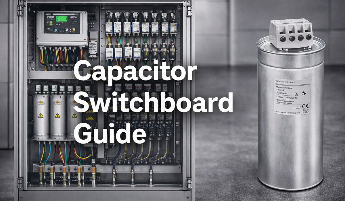
Where the correction equipment is built as a dedicated assembly rather than fitted inside an existing board, the design follows the same conventions as other capacitor switchboards.
Equipment Lifespan and Thermal Stress
One of the other reasons that emphasize the necessity of capacitor banks is the reduced lifespan of electrical equipment. The absence of a capacitor bank and the presence of excessive reactive power can put a heavy strain on electrical equipment. Inductive loads like motors and transformers generate reactive power, which leads to additional currents and voltage fluctuations. These extra currents cause heat generation and increase the temperature of the equipment, ultimately leading to faster wear and tear and a reduction in their useful life. Installing a capacitor bank to compensate for reactive power prevents these issues, improves equipment performance, and extends their lifespan.
Every degree of additional operating temperature accelerates the degradation of insulation materials in motors and transformers. The familiar rule of thumb here — known as the 10-degree rule, or Montsinger’s rule — holds that insulation life is roughly halved for every 10 °C rise above the rated operating temperature. It is an approximation rather than a standard requirement, but it explains why continuous thermal stress accumulates silently until a failure occurs. Capacitor banks address this at the root cause, keeping equipment temperatures within design limits and preserving the full rated service life of each asset.
Table 2 — Effect of no compensation, by equipment type
| Equipment Type | Effect Without a Capacitor Bank |
|---|---|
| Electric motors | Winding overheating, insulation degradation, bearing stress and reduced efficiency |
| Transformers | Core heating, increased copper losses, oil degradation in oil-filled units, shortened service life |
| Cables and busbars | Accelerated insulation ageing, higher short-circuit risk, reduced current-carrying capacity over time |
| Switchgear and breakers | Contact erosion from higher interrupting currents, more frequent tripping, reduced breaking capacity margin |
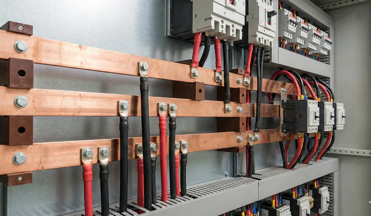
Conductors carry the same penalty. Excess reactive current heats every metre of the distribution path, which is why busbars in modern electrical systems are sized against the current they actually carry rather than the active load alone.
Voltage Stability and Overvoltage Risk
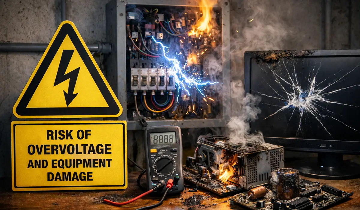
A major issue in electrical systems operating without a capacitor bank is the risk of overvoltage. When reactive power is not controlled within the system, voltage fluctuations and disturbances occur, which can cause serious damage to sensitive equipment. These overvoltages lead to premature wear of devices, sudden failures, and even permanent damage to electrical components. A capacitor bank, by compensating for reactive power, not only improves the system’s power factor but also prevents voltage fluctuations, reducing the risk of damage to equipment.
Sensitive electronic equipment — including programmable logic controllers, variable-speed drives, and precision instrumentation — is particularly vulnerable to voltage transients and sustained overvoltage conditions. A single overvoltage event can corrupt control software, damage semiconductor components, or permanently destroy measurement circuits. The cost of replacing or repairing such equipment, combined with unplanned production downtime, far exceeds the investment required to install a properly designed capacitor bank with appropriate overvoltage protection measures.
One caveat worth stating plainly: correction can overshoot. An over-compensated bank on a light load pushes the system into leading power factor and raises voltage rather than steadying it, which is why automatic control matters. Voltage limits and clearance requirements also differ sharply between voltage bands — see high voltage vs low voltage for where the thresholds sit.
Power Losses and Machine Efficiency
In electrical systems without capacitor banks, the excess reactive power results in power losses, which add an extra load on machinery. This reduces the efficiency of the machines and increases energy consumption. In such cases, machines require more power to perform routine tasks, which not only decreases system efficiency but also leads to higher wear and tear and more frequent repairs. By using a capacitor bank, reactive power is compensated, the power factor is improved, and the efficiency of machines is increased, resulting in lower energy consumption and better overall performance.
Reactive current is only half the loss picture. Harmonic current from drives and rectifiers heats conductors beyond what the RMS value alone suggests, and correcting that requires a different device — this guide to harmonic filters covers the passive, active and reactor-based options.
Table 3 — Performance with compensation
| Performance Indicator | With a Capacitor Bank |
|---|---|
| Power factor | Corrected toward unity; reactive current minimised; active current used efficiently |
| Energy losses | I²R losses in cables and equipment significantly reduced; less energy wasted as heat |
| Machine efficiency | Machines operate at rated load conditions; less mechanical and thermal stress; fewer unplanned stoppages |
| Voltage stability | Voltage profile stabilised across load conditions; equipment operates within rated voltage tolerances |
Network Stability and Unplanned Outages
An unstable power network and frequent power outages can cause serious problems for industries and buildings. These instabilities are usually due to issues such as excessive reactive power, voltage fluctuations, and added strain on energy transmission equipment. When an electrical system has excessive and uncontrolled reactive power, the extra currents and voltage fluctuations reduce power quality, leading to network instability. This instability can result in frequent power outages and even damage to sensitive equipment.
Installing a capacitor bank effectively compensates for reactive power and prevents voltage fluctuations, improving power quality and reducing strain on the power network.
Network instability has cascading consequences that extend well beyond the immediate electrical infrastructure. In manufacturing environments, unexpected power interruptions can halt production lines mid-cycle, causing material waste and product quality failures. In process industries such as chemical plants and food production facilities, sudden outages can compromise batch integrity, trigger safety shutdowns, and require lengthy restart procedures. The business cost of these interruptions — lost production, scrapped product, emergency labour, and customer penalties — is typically orders of magnitude greater than the cost of installing the capacitor bank that could have prevented them.
The correction equipment does not sit in isolation either. It shares a bus with everything else in the distribution system, so the design of the surrounding industrial electrical switchboards determines how far a disturbance travels.
Does a Capacitor Bank Consume Power?
A capacitor bank supplies reactive power (kVAR) rather than consuming active power (kW) — but it is not completely lossless.
The distinction decides whether the bank appears on your energy bill as a cost or a saving.
What it does not consume. A capacitor does not convert electrical energy into useful work or waste heat the way a motor or heater does. Energy moves back and forth between the capacitor and the network twice per cycle, and net active power transfer over a full cycle is close to zero.
What it does consume. Three small active loads exist in any real bank:
- Dielectric losses in the capacitor film, dissipated as heat. Small in normal service, but they rise sharply if the capacitor is running hot or carrying harmonic current.
- Discharge resistors, permanently connected to bleed stored charge after disconnection. A safety requirement, and a permanent small draw.
- Auxiliaries — the power factor controller, contactor coils, and any enclosure cooling fans.
Manufacturer datasheets state total losses in watts per kVAR. On a correctly designed bank these are a small fraction of the I²R losses the same installation removes upstream, which is why a properly sized bank reduces total energy consumption rather than adding to it.
The exception is over-compensation. If the bank pushes power factor into leading territory during light load, reactive current flows in the opposite direction and the losses return — along with a voltage rise. Automatic banks with a correctly configured controller avoid this. A fixed bank on a variable load does not.
When a Capacitor Bank Makes Things Worse: Harmonic Resonance
Everything above assumes a reasonably linear plant. In a facility with variable-speed drives, rectifiers, UPS systems or LED drivers, the picture changes — and this is the most expensive mistake in power factor correction.
A capacitor bank does not remove harmonics. It can amplify them.
The capacitance of the bank and the inductance of the upstream transformer and cables form a parallel resonant circuit. If its resonant frequency lands near a harmonic the plant already produces — most often the 5th, at 250 Hz on a 50 Hz system — harmonic current is amplified rather than absorbed. Capacitor banks without detuned reactors tend to create parallel resonance with the upstream system at harmonic frequencies, especially the 5th and 7th, and the result is significant amplification of harmonic current into the capacitors, causing insulation failure, overheating, and elevated voltage distortion across busbars.
The symptoms are recognisable: capacitors failing early, contactors welding, audible humming from the bank, and THD that gets worse after commissioning rather than better.
The fix is a detuned reactor — a series inductor in each capacitor step, sized so the LC combination resonates below the lowest significant harmonic. Detuned reactors are typically specified with a tuning frequency of 189 Hz (7%) or 134 Hz (14%) on 50 Hz systems. The relationship is fr = f1 / √p, and 189 Hz sits safely below the 5th harmonic at 250 Hz.
A practical selection rule: if more than 20–30% of facility load is supplied through variable frequency drives, rectifiers or other non-linear sources, always specify a detuned bank.
One design consequence to plan for: a detuned reactor raises the fundamental voltage across the capacitor. At 400 V with 7% detuning the capacitor sees roughly 430 V, so capacitors in detuned banks must be rated above system nominal voltage. Fitting standard 400 V capacitors behind a detuned reactor is a guaranteed early failure.
Low Voltage Capacitor Banks and the Standards That Apply
For industrial power systems at 1000 V and below, four IEC documents define what a compliant capacitor bank looks like.
| Standard | Scope |
|---|---|
| IEC 61921 | Power capacitors — low-voltage power factor correction banks (the complete assembly) |
| IEC 60831-1 / -2 | Shunt power capacitors, self-healing type, AC systems up to and including 1000 V |
| IEC 60931-1 | Shunt power capacitors, non-self-healing type, AC systems up to and including 1000 V |
| IEC 60871-1 | Shunt capacitors for AC power systems above 1000 V |
The connection panel builders should notice: IEC 61921 requires that low-voltage power factor correction banks comply with IEC 61439-1 and IEC 61439-2 where applicable.
An LV capacitor bank is not a box of capacitors. It is a low-voltage assembly, and it carries the same verification obligations as any other — temperature rise, dielectric properties, clearances and short-circuit withstand. That is where internal busbar geometry and joint quality stop being a detail: capacitor steps switch frequently, and joint integrity decides whether the assembly holds its verified temperature rise through years of duty cycling.
The incoming device follows the same logic. A capacitor bank needs isolation for maintenance and a switching device rated for capacitive duty, both selected under IEC 60947-3 — the distinction between a switch, a disconnector and a switch-disconnector is set out in this guide to electrical switches and their standards.
Installing and Commissioning an Industrial Capacitor Bank
Capacitor banks are devices used to improve the power factor and reduce energy losses in electrical systems. Their installation is crucial for optimizing energy consumption and reducing costs. The process of installing and commissioning a capacitor bank includes the following steps.
Types of Capacitor Banks
- Fixed: A single, permanently connected block of capacitance. Suitable only where reactive demand is steady — for example, an individual motor compensated at its own terminals.
- Automatic (APFC): Several switched steps under a power factor controller, which brings capacitance in and out as the load varies. The default choice for most plants.
- Detuned: An automatic bank with a series reactor in every step. Required wherever significant harmonic load is present.
- Thyristor-switched: Solid-state switching for loads that change faster than a contactor-based bank can follow, such as welding plant or crane duty.
Switching itself is not a bank type — it is the mechanism inside an automatic bank, and the contactors that perform it must be rated for capacitive duty.
How to Calculate the Required Capacity
To size a capacitor bank, first establish the reactive power the system actually draws, then determine how much reactive power is needed to lift the measured power factor to the target. The bank is sized to close that gap — not to reach unity, and not from a rule of thumb. Measurement across a full production cycle matters more than any single reading, because a bank sized on peak demand will over-compensate at light load.
Installation Steps
Table 4 — Installation and commissioning
| Installation Step | Key Requirement |
|---|---|
| Assess system needs | Use a power analyser over a representative period to capture reactive power demand at all load conditions, and measure harmonic spectrum |
| Select capacitor bank | Match type (fixed, automatic or detuned) and kVAR rating to the measured reactive power and harmonic profile |
| Specify switching | Use capacitor-duty contactors with pre-charging resistors — capacitor inrush on single-step energisation is severe and welds standard contactors |
| Install equipment | Follow manufacturer wiring diagrams; verify CT ratio, contactor ratings and cable sizing |
| Initial testing | Energise in stages; verify controller response; confirm no harmonic resonance before full-load operation |
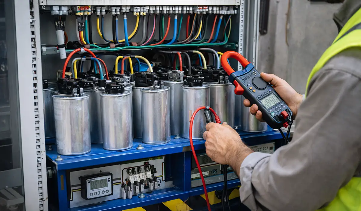
| Monitoring and operation | Log power factor, temperature and switching frequency; schedule periodic capacitor and contactor inspection |
The controller, contactors, fuses and CT are all specified together rather than in isolation, which is the same discipline applied to every other group of industrial electrical panel components.
Conclusion
Installing a capacitor bank is an effective solution for enhancing the performance of industrial and commercial electrical systems. The benefits include reduced electricity costs, extended equipment lifespan, improved power factor, lower energy losses, and fewer power quality disturbances. The case is strongest on variable loads and in systems carrying significant reactive demand.
Three decisions carry most of the outcome: size the bank from measured reactive power rather than a rule of thumb, choose automatic control unless the load is genuinely constant, and specify a detuned bank wherever drives or rectifiers make up a meaningful share of the load. Getting the third one wrong is what turns a power factor project into a power quality problem.
For panel builders, the bank is a verified low-voltage assembly like any other, and busbar geometry, joint quality and clearances decide whether it holds its temperature rise in service. Explore PAYAPRESS CNC busbar fabrication machines for busbar processing that supports IEC 61439 verification.


Rate this article
Choose a rating from 1 to 5 stars.
No ratings yet