






What Is Voltage? (Electric Potential Difference)
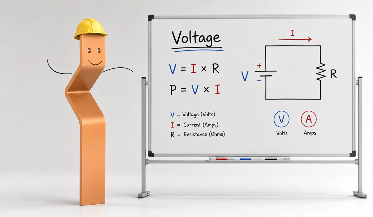
To make voltage current and resistance explained simply, we start with voltage. It is the electric potential difference between two points in a circuit. In plain terms, voltage represents the “pressure” that pushes electric charge through wires. Without this potential difference, no current flows.
The volt (V) is the SI unit for voltage. The unit honors Italian physicist Alessandro Volta, who built the first chemical battery in 1800. Consequently, his name appears on every multimeter, datasheet, and electrical code worldwide.
Several sources create voltage. Batteries use chemical reactions to push electrons. Generators rely on electromagnetic induction inside rotating coils. Additionally, power supplies convert mains voltage into stable DC levels for circuit boards and industrial controllers.
Practical voltage levels span a huge range. For example, a AA cell delivers 1.5 V, a USB port supplies 5 V, and household outlets carry 120 V in the US or 230 V in the EU. Industrial motors often run at 400 V or higher.
That sums up what is voltage in electricity at its core. It is a measure of energy per unit charge, and it drives every device from sensors to factory drives.
You can explore this trusted source for more complete and updated information about Beginner-friendly lesson on electric potential, the volt as a unit, and how potential difference drives charge through a circuit.
What Is Electric Current?
Electric current is the actual flow of charge through a conductor. While voltage provides the push, current shows the result. In any electrical basics for beginners voltage current resistance discussion, current is the moving part of the picture.
The ampere (A) is the SI unit for current. The unit honors French scientist André-Marie Ampère. One ampere equals one coulomb of charge passing a point each second. Therefore, the amperage definition simply means the rate of charge flow.
Two conventions describe current direction. Conventional current flows from positive to negative terminals. Electron flow, in contrast, moves the opposite way because electrons carry negative charge. However, both descriptions yield identical circuit equations.
Current also comes in two forms. Direct current (DC) flows steadily in one direction, as in batteries and solar panels. Alternating current (AC), in contrast, reverses periodically and powers most homes, offices, and factories worldwide.
Practical examples help anchor the idea. A phone charger pulls about 1–2 A. A small LED uses only about 20 mA. Meanwhile, an industrial heater can draw 50 A or more under full load, and a car starter motor can briefly pull hundreds of amps.
This source can help you verify the information and continue your independent research about Detailed physics explanation of electric current, its units, and the relationship between charge flow and amperage.
What Is Electrical Resistance?
Electrical resistance describes how strongly a material opposes the flow of current. Every conductor offers some resistance, although the amount varies widely between materials. In short, resistance answers what is resistance in a circuit clearly.
The ohm (Ω) serves as the SI unit. The unit honors Georg Simon Ohm, a German physicist who published his famous work in 1827. As a result, every resistor today carries values stated in ohms.
Four main factors set the resistance of a wire. First, material type matters; copper conducts well, while rubber blocks current. Second, longer wires resist more. Third, thicker wires resist less because electrons have more space. Finally, higher temperatures usually raise resistance in metals.
Materials sort into three broad groups based on resistance behavior. Conductors carry charge easily, insulators block it almost entirely, and semiconductors fall between. The comparison table below summarizes typical examples for each group.
Understanding resistance helps engineers size cables, choose protective resistors, and prevent overheating. Consequently, every datasheet and wiring code references resistance values precisely. In addition, accurate resistance measurement supports troubleshooting on busy factory floors.
| Material Type | Example | Resistance Level | Typical Use |
|---|---|---|---|
| Conductor | Copper wire | Low | Power and signal wiring |
| Semiconductor | Silicon | Medium | Diodes, transistors, chips |
| Insulator | Rubber | Very high | Cable jackets, glove material |
| Resistor alloy | Nichrome wire | High (controlled) | Heating elements, resistors |
You can review the original source here to verify the technical details about Practical guide from a leading test equipment manufacturer covering resistance, its units, and measurement methods.
Ohm’s Law — How Voltage, Current, and Resistance Relate
Georg Ohm discovered a simple but powerful link between voltage, current, and resistance. He published the rule in 1827. Today engineers call it Ohm’s Law, and it underpins every ohm’s law explained tutorial in the world.
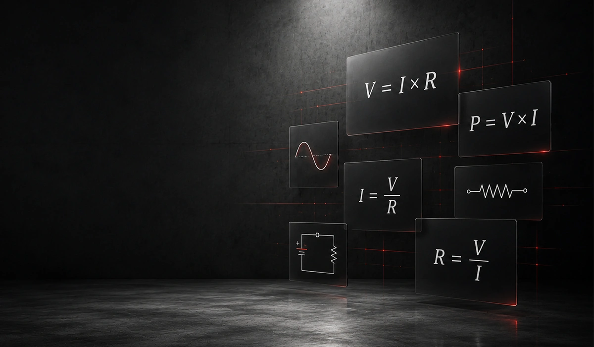
The core formula is V = I × R. Here V stands for voltage in volts, I stands for current in amperes, and R stands for resistance in ohms. Therefore, knowing any two values reveals the third.
Three forms make the law easy to apply in real circuits. Use V = I × R to find voltage. Use I = V / R to find current. Finally, use R = V / I to find resistance.
Consider three quick examples. A 12 V battery across a 4 Ω resistor produces 3 A. A device drawing 2 A through 5 Ω needs 10 V. A 9 V supply pushing 3 A through a load shows 3 Ω of resistance.
These ohm’s law formula and examples form the practical foundation of voltage current and resistance explained at a circuit level. Engineers use them daily to size components, set trip thresholds, and learn how to calculate voltage using ohm’s law.
| What You Need to Find | Formula | When to Use It |
|---|---|---|
| Voltage (V) | V = I × R | Current and resistance are known |
| Current (I) | I = V / R | Voltage and resistance are known |
| Resistance (R) | R = V / I | Voltage and current are known |
For updated product, service, or technical information about Engineering textbook section covering Ohm’s Law, its derivation, and worked examples in real DC circuits, review the source website directly.
The Ohm’s Law Triangle (Visual Memory Aid)
The Ohm’s Law triangle is a simple visual tool. Place V at the top, with I at the bottom left and R at the bottom right. To find any variable, cover it with a finger. The remaining two letters then form the correct formula.
For example, covering V leaves I and R side by side, giving V = I × R. Covering I leaves V over R, giving I = V / R. This trick prevents formula confusion under field pressure.
V
───
I R
For readers who want more technical depth about Clear walkthrough of the Ohm’s Law triangle and how to derive each variable, this reference page is a useful starting point.
Real-World Analogy — The Water Pipe Model
Imagine water moving through a pipe. The pressure pushing water forward represents voltage. The water itself, flowing along, represents current. Meanwhile, the pipe’s diameter and obstacles inside represent resistance. This picture captures the voltage current resistance relationship perfectly.
Now picture turning up the pump. As pressure rises, water flows faster through the same pipe. Similarly, when voltage increases across a fixed resistance, current rises too. The water analogy explains how are voltage current and resistance related in everyday terms.
Next, imagine pinching the pipe narrower. The flow drops even though pressure stays the same. In a circuit, this matches what happens when resistance increases in a circuit; current falls while voltage holds steady at the source.
Finally, picture clearing and widening the pipe. Flow surges with less effort. Thicker copper conductors behave the same way, carrying more amps with less heat loss. Therefore, plumbing intuition guides electrical design in both small electronics and large industrial systems.
In short, the same three forces show up in plumbing and in wiring. Once the analogy clicks, engineers can predict circuit behavior almost on sight before reaching for a meter.
Visit this page to learn more about the specifications, applications, and related details about Hands-on tutorial using the water analogy to teach electrical concepts to beginners.
Why These Three Concepts Matter in Electronics
Mastering these three quantities prevents costly mistakes on bench and plant floor. Engineers who skip the basics often size components wrong, blow fuses, or destroy expensive equipment. In contrast, those who internalize how electricity works basics design safer, more efficient circuits.
Specifically, these concepts guide everyday design choices:
- Sizing wires to avoid overheating under sustained load
- Selecting current-limiting resistors for LEDs and sensors
- Picking fuses and breakers that protect without nuisance tripping
- Reading component datasheets to match voltage and current ratings
- Calculating power dissipation in resistors and switching devices
In industrial settings, this knowledge scales up quickly. Motor drives, transformer banks, and switchgear all depend on the same three quantities. As a result, plant engineers troubleshoot faster when they understand the underlying physics.
Beyond design, safety depends on these concepts. High voltage needs proper insulation and clearance. High current needs adequate conductor cross-sections. Therefore, electrical codes worldwide reference voltage current and resistance explained in standard tables.
For business owners, this knowledge cuts operating costs. The right cable size reduces energy loss across long runs. Matching motors to supply voltage extends equipment life. Therefore, even non-engineers benefit from a basic grasp of the rules.
Conclusion
Voltage, current, and resistance form the trio every electrical worker must master. Voltage pushes charge, current carries it, and resistance holds it back. Together, they explain how every circuit behaves under load.
Ohm’s Law, V = I × R, ties the three together with one compact equation. Furthermore, the water pipe analogy makes the relationship intuitive even for those new to electronics.
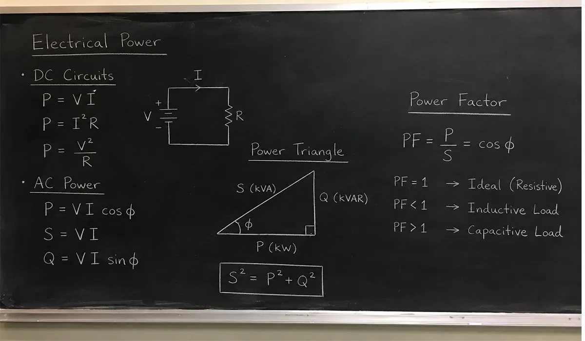
For practical work, remember the key takeaways. Higher voltage drives more current through fixed resistance. Higher resistance cuts current at fixed voltage. Power equals voltage times current. Notably, these rules apply to almost every DC circuit and most low-frequency AC circuits you will meet on the job.
With voltage current and resistance explained in plain terms, you now hold the foundation for deeper topics. Series and parallel circuits, AC analysis, and power electronics all build on the same three quantities. Therefore, time spent here pays off in every advanced subject.
Finally, every working engineer keeps a multimeter handy. The meter measures all three quantities directly on real circuits. As a result, the link between theory and practice is always one probe-touch away, whether you work on a hobby board or a factory cabinet.



Rate this article
Choose a rating from 1 to 5 stars.
No ratings yet