






What Is Electrical Power? A Working Definition
Electrical power is the rate at which electrical energy moves through a circuit or converts into another form, such as heat, light, or mechanical motion. The base unit is the watt (W), where one watt equals one joule per second. Engineers use the symbol P for power and scale up to kilowatts (kW) or megawatts (MW) for industrial systems.
Importantly, power describes a rate rather than a quantity of energy. A 100 W lamp running for one hour consumes 0.1 kWh of energy; the 100 W figure tells you only how fast that energy flows. Furthermore, in DC circuits and purely resistive AC loads, the electrical power formula is straightforward and identical in shape.
However, AC circuits with reactive elements behave differently. Inductors and capacitors store and release energy each cycle. As a result, voltage and current can drift out of phase, which forces engineers to split power into three categories: real, reactive, and apparent. This split underpins every later section of this guide and also shapes how utilities bill industrial consumers.
These power formulas build directly on Ohm’s Law and the basics of voltage, current, and resistance. For a full breakdown, see Electrical Fundamental.
Electrical Power in DC Circuits
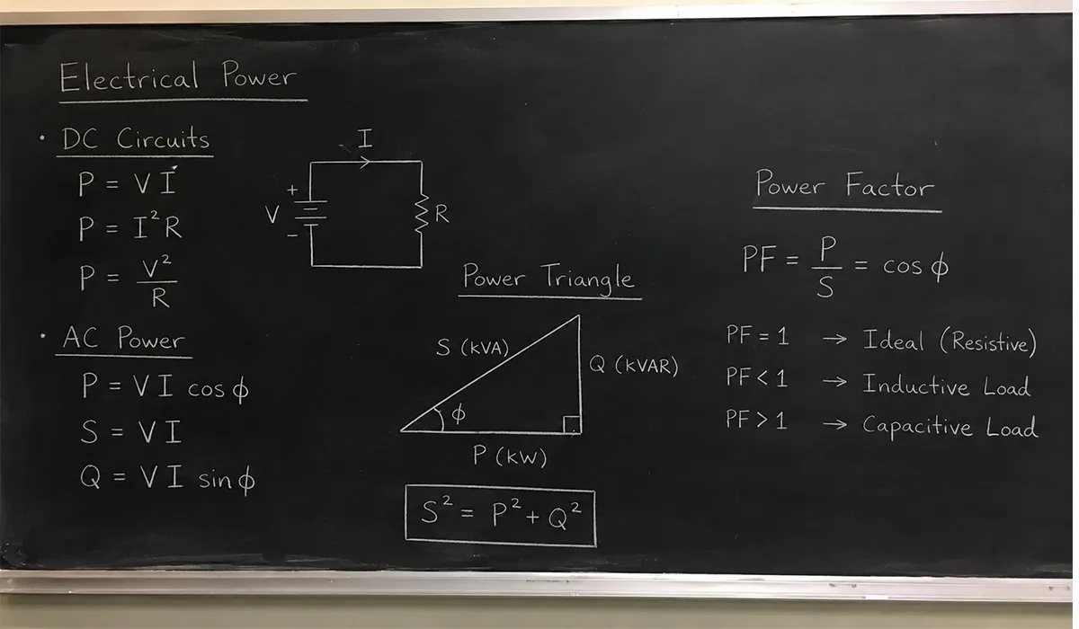
DC power calculation is the simplest case and the foundation for understanding all AC systems. In a direct current circuit, both voltage and current remain constant over time. Therefore, instantaneous and average power values are identical, which removes complications from phase or frequency.
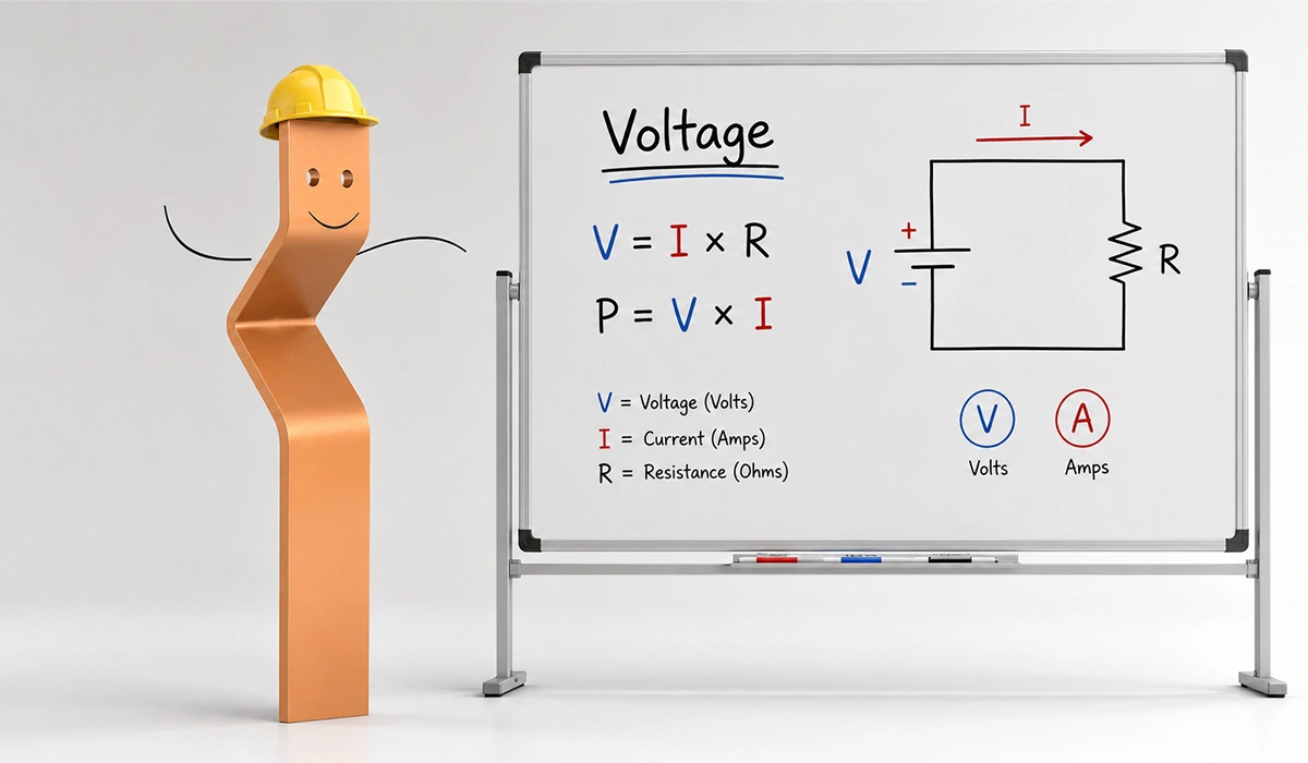
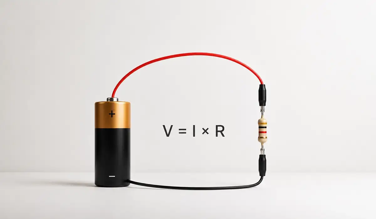
The core equation is Watt’s Law: P = V × I, where P is power in watts, V is voltage in volts, and I is current in amperes. Combined with Ohm’s Law (V = IR), two equivalent forms follow naturally. Consequently, you can compute power in a DC circuit from any two known quantities.
| Formula | Use When | Derived From |
|---|---|---|
| P = V × I | Voltage and current are known | Direct definition |
| P = I² × R | Current and resistance are known | Substituting V = IR |
| P = V² ÷ R | Voltage and resistance are known | Substituting I = V/R |
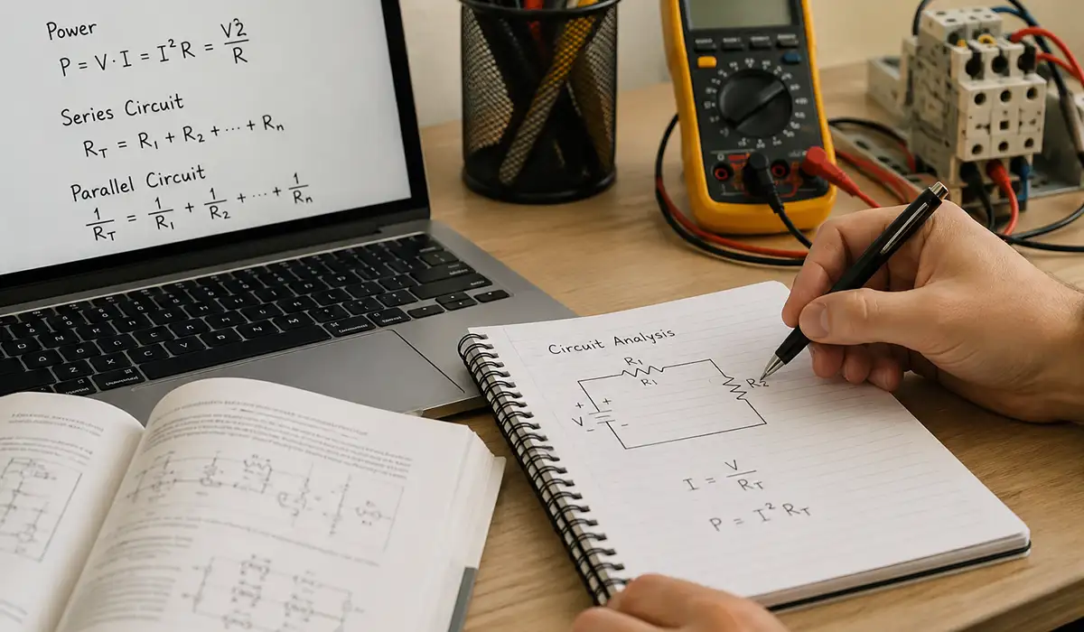
All three expressions describe the same physical relationship. They are algebraic rearrangements, not separate laws. Practically, you simply choose the form that matches the quantities already on your schematic or measurement instrument. This same logic extends to series and parallel sub-circuits.
Worked Example — DC Power Calculation
Problem 1: A 24 V DC control circuit draws 3.5 A. Find the power consumption. Solution: P = V × I = 24 × 3.5 = 84 W.
Problem 2: A 10 Ω resistor carries 2 A. Find the dissipated power. Solution: P = I² × R = 4 × 10 = 40 W.
These results highlight a basic design rule. You must select components rated above the dissipated wattage; otherwise, overheating and premature failure follow quickly.
You can review the original source here to verify the technical details about Worked DC examples that walk through Watt’s Law applications step by step.
Understanding AC Power: Why It Is More Complex
Alternating current introduces time-varying voltage and current waveforms, which fundamentally change how engineers compute power. Both quantities oscillate sinusoidally, so instantaneous power also varies throughout each cycle. Average values, not peaks, drive useful work.
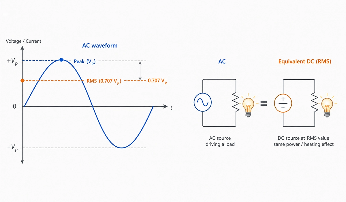
In a purely resistive AC load, voltage and current rise and fall together. The power calculation then resembles DC analysis, with one critical caveat: V and I must be expressed as RMS (root mean square) values. Notably, RMS voltage is the equivalent DC voltage that produces the same heating in a resistor.
However, real industrial loads include inductors in motors and capacitors in filters or correction banks. These reactive components store energy and return it to the source each cycle, which shifts the current waveform relative to voltage. This phase shift introduces the power factor.
| Power Type | Symbol | Unit | What It Represents |
|---|---|---|---|
| Active Power | P | W or kW | Useful work or heat |
| Reactive Power | Q | VAR or kVAR | Energy exchanged with reactive elements |
| Apparent Power | S | VA or kVA | Total delivered by the source |
Together, P, Q, and S form the power triangle, where S² = P² + Q². This geometric relationship anchors every AC calculation in the rest of the guide.
Visit the linked website to better understand the background, standards, and practical use cases of National metrology guidance on AC voltage, current, and power measurement.
Power Factor: What It Is and Why It Matters
Power factor (PF) is the ratio of active power to apparent power: PF = P ÷ S, which also equals cos(φ), where φ is the phase angle between voltage and current. The value is dimensionless and lies between 0 and 1. Engineers often express it as a percentage as well.
A unity power factor of 1.0 means every watt the source supplies perform useful work. This ideal occurs only with purely resistive loads. Below unity, some of the supplied power circulates without doing useful work, so the source must deliver more current for the same output.
Consequently, poor power factor increases conductor heating, transformer loading, and switchgear stress. Utilities frequently penalize industrial users with PF below 0.90 because low power factor strains the grid without generating billable energy.
| Active Power | Power Factor | Apparent Power Required |
|---|---|---|
| 100 kW | 1.00 | 100 kVA |
| 100 kW | 0.95 | 105.3 kVA |
| 100 kW | 0.85 | 117.6 kVA |
| 100 kW | 0.75 | 133.3 kVA |
| 100 kW | 0.65 | 153.8 kVA |
At 0.65 PF, the source must supply 54% extra capacity for the same useful output, which makes the cost of poor power factor immediately visible.
Single-Phase AC Power Formula
The single-phase power formula reflects the role of power factor in real AC loads. For a purely resistive single-phase load, the equation reduces to P = V × I, identical in form to DC. However, most practical circuits include some reactance, so the general form applies: P = V × I × cos(φ), where V and I are RMS values.
Additionally, you can calculate apparent power and reactive power for the same circuit. Together, these three quantities describe the complete power delivery profile and let you size cables and protective devices correctly.
| Quantity | Formula | Unit |
|---|---|---|
| Active Power | P = V × I × cos(φ) | W or kW |
| Apparent Power | S = V × I | VA or kVA |
| Reactive Power | Q = V × I × sin(φ) | VAR or kVAR |
| Power Factor | PF = P ÷ S | — |
Notably, beginners often confuse peak and RMS values. Wall outlets in Europe deliver 230 V RMS, which corresponds to a peak of about 325 V. All AC power equations assume RMS unless stated otherwise. Furthermore, instrument manuals consistently report RMS readings on standard ammeters and voltmeters.
This website offers useful supporting information for understanding Manufacturer guidance on single-phase power measurement with clamp meters and analyzers more clearly.
Worked Example — Single-Phase AC Power Calculation
Problem: A 230 V single-phase motor draws 8 A at a power factor of 0.85. Find P, S, and Q.
- Apparent power: S = 230 × 8 = 1,840 VA = 1.84 kVA
- Active power: P = S × PF = 1,840 × 0.85 = 1,564 W = 1.564 kW
- Reactive power: Q = √(S² − P²) ≈ 969 VAR
Therefore, the motor consumes 1.84 kVA from the supply, but only 1.564 kW becomes mechanical work. The remaining 969 VAR oscillates between source and windings.
Three-Phase AC Power Formula
Three-phase systems dominate industrial and commercial distribution because they deliver more power per conductor than single-phase systems. Additionally, instantaneous power in a balanced three-phase circuit stays constant. As a result, motors and large loads run without torque pulsation, and most equipment above a few kilowatts uses three-phase supply.
The standard three-phase power formula for a balanced load uses line quantities: P = √3 × V_L × I_L × cos(φ). Here V_L is line-to-line voltage, I_L is line current, and √3 ≈ 1.732 arises from the 120° phase separation between the three-line voltages.
| Quantity | Formula | Unit |
|---|---|---|
| Active Power | P = √3 × VL × IL × cos(φ) | W or kW |
| Apparent Power | S = √3 × VL × IL | VA or kVA |
| Reactive Power | Q = √3 × VL × IL × sin(φ) | VAR or kVAR |
| Power Factor | PF = P ÷ S | — |
| Configuration | Line Voltage (VL) | Phase Voltage Relationship |
|---|---|---|
| Star (Wye) | Between any two lines | VL = √3 × VPh |
| Delta | Between any two lines | VL = VPh |
The same formula applies to both star and delta loads when you use line quantities consistently. Consequently, total power stays identical for a load connected in either topology at the same line voltage.
You can visit the official website for more detailed and updated information about Engineering references on three-phase distribution, motors, and switchgear.
Worked Example — Three-Phase Power Calculation
Problem: A three-phase motor runs on 400 V line-to-line, draws 15 A line current, with PF = 0.88. Find P, S, and Q.
- Apparent power: S = √3 × 400 × 15 ≈ 10,392 VA ≈ 10.39 kVA
- Active power: P = S × 0.88 ≈ 9,145 W ≈ 9.15 kW
- Reactive power: Q = √(S² − P²) ≈ 4,936 VAR ≈ 4.94 kVAR
Therefore, the motor takes 10.39 kVA from the grid; 9.15 kW becomes useful mechanical output, while 4.94 kVAR sustains the magnetic field in the windings.
Three-Phase Power in Star vs. Delta: Does the Formula Change?
The formula P = √3 × V_L × I_L × cos(φ) applies to both star and delta configurations as long as you stick to line quantities. The difference lies in how line and phase quantities relate, not in the total power equation itself.
- Star (wye): phase current = line current; phase voltage = V_L ÷ √3
- Delta: phase voltage = line voltage; phase current = I_L ÷ √3
Consequently, total power stays identical for the same load reconfigured between the two topologies at the same line voltage.
Complete Electrical Power Formula Reference
Reference: IEEE Xplore — Authoritative library of power engineering standards, papers, and reference works.
This reference table consolidates every equation introduced above. Engineers, electricians, and panel builders can use it as a quick lookup during design, commissioning, and field troubleshooting.
| Circuit Type | Quantity | Formula | Unit |
|---|---|---|---|
| DC | Active Power | P = V × I | W |
| DC | Active Power | P = I² × R | W |
| DC | Active Power | P = V² ÷ R | W |
| Single-Phase AC | Active Power | P = V × I × cos(φ) | W |
| Single-Phase AC | Apparent Power | S = V × I | VA |
| Single-Phase AC | Reactive Power | Q = V × I × sin(φ) | VAR |
| Single-Phase AC | Power Factor | PF = P ÷ S = cos(φ) | — |
| Three-Phase AC | Active Power | P = √3 × VL × IL × cos(φ) | W |
| Three-Phase AC | Apparent Power | S = √3 × VL × IL | VA |
| Three-Phase AC | Reactive Power | Q = √3 × VL × IL × sin(φ) | VAR |
| Three-Phase AC | Power Factor | PF = P ÷ S = cos(φ) | — |
| All AC | Power Triangle | S² = P² + Q² | — |
| All AC | kVA to kW | kW = kVA × PF | — |
Notably, this set covers most practical needs. However, for unbalanced three-phase loads, harmonic-rich drives, or distorted waveforms, more advanced techniques such as two-wattmeter measurement or harmonic decomposition become necessary.
Checkout this Authoritative library of power engineering standards, papers, and reference works.
Conclusion about Electrical Power Formula
The electrical power formula scales from a simple P = V × I in DC circuits to the √3-weighted form used in three-phase industrial systems. Across all variants, the underlying principle stays the same: power is the rate of energy transfer, expressed in watts, kilowatts, or megawatts. AC systems add the phase angle and therefore require careful separation of real, reactive, and apparent power.
For engineers and electricians, mastering these equations means correct cable sizing, accurate motor selection, and informed power factor correction decisions. Practically, even a modest improvement from 0.75 to 0.95 power factor cuts apparent power demand by roughly 20%, which lowers utility penalties and frees transformer capacity. Therefore, treat the power triangle and the kVA-to-kW relationship as everyday tools, not academic concepts. With the reference table above, you can verify field calculations without reaching for a textbook.


Rate this article
Choose a rating from 1 to 5 stars.
5.0 out of 5 — 2 votes