






For your convenience, if you prefer listening, you can listen to the rest of this article via the audio file below.
What Is Ohm’s Law? A Simple Starting Point
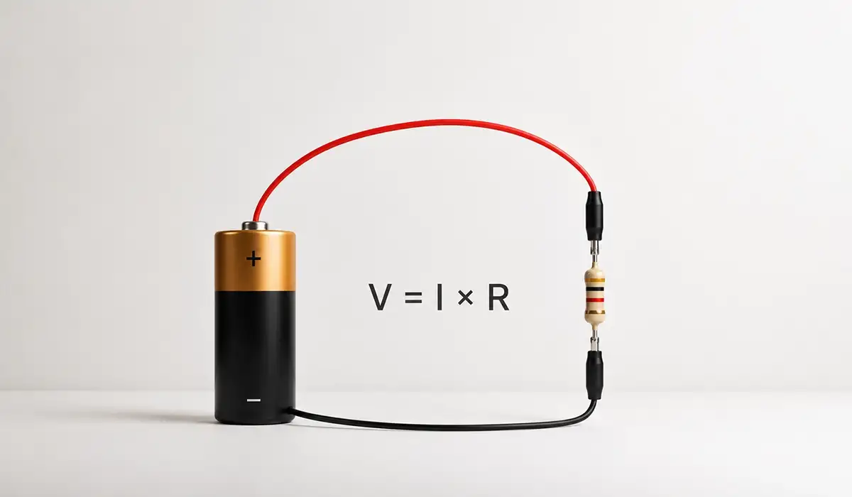
In its simplest form, Ohm’s Law states that the current flowing through a conductor between two points is directly proportional to the voltage across those points, provided temperature and other physical conditions stay constant. Therefore, doubling the voltage doubles the current, while doubling the resistance halves it.
The German physicist Georg Simon Ohm published this relationship in 1827. Although his work met early skepticism, it soon became one of the most widely used relationships in electrical engineering and electronics.
Importantly, the principle applies to resistive — or ohmic — conductors and underpins nearly every basic circuit calculation. Indeed, it links the three core variables of any DC circuit: voltage (V), current (I), and resistance (R).
If you are looking for more information about Electrical Fundamentals, it is recommended not to miss reading this article.
Beginners can think of it as the grammar of electricity. Once you know the rule, you can analyses, design, and troubleshoot simple circuits with confidence.
This external page provides additional insights about Plain-language introduction to circuit fundamentals from a respected nonprofit education platform that may help with your evaluation.
The Three Variables: Voltage, Current, and Resistance
Before applying the formula, every learner needs a clear picture of the three quantities involved. The table below summarizes the voltage-current-resistance relationship in compact form.
| Quantity | Symbol | Unit | Unit Symbol | What It Represents |
|---|---|---|---|---|
| Voltage | V (or E) | Volt | V | Electrical pressure driving current through a circuit |
| Current | I | Ampere | A | Rate of flow of electric charge through a conductor |
| Resistance | R | Ohm | Ω | Opposition a material offers to the flow of current |
Voltage is the potential difference between two points. Picture water pressure inside a pipe: higher pressure pushes more water along. Engineers measure voltage with a voltmeter placed across two points in a circuit.
Current is the actual flow of electrons through a conductor. Continuing the water analogy, current is the flow rate rather than the pressure. Technicians measure it with an ammeter wired in series.
Resistance is the property that opposes current flow and converts electrical energy into heat. Every conductor has some, while resistors introduce a controlled amount on purpose.
You can review the original source here to verify the technical details about Practical reference from a leading test-equipment manufacturer used widely by field engineers.
The Ohm’s Law Formula: V = IR
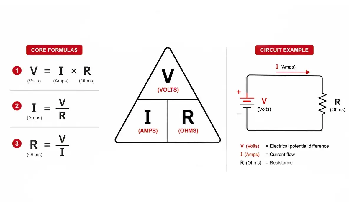
The Ohm’s Law formula expresses the entire relationship in one short line:
V = I × R
Where V is voltage in volts, I is current in amperes, and R is resistance in ohms. From this single equation, you can solve for any one variable when the other two are known.
| To Find | Formula | Use When |
|---|---|---|
| Voltage (V) | V = I × R | Current and resistance are known |
| Current (I) | I = V ÷ R | Voltage and resistance are known |
| Resistance (R) | R = V ÷ I | Voltage and current are known |
The three rearranged forms — for voltage, current, and resistance — all come from the same underlying relationship. Therefore, once you understand one form, the others follow naturally from simple algebra.
Beginners often worry about memorizing three separate formulas. However, you really only need one. The rest fall out the moment you isolate the variable you want.
For a comprehensive understanding of Voltage, Current, and Resistance Explained we highly recommend reviewing this article.
The Ohm’s Law Triangle: A Visual Memory Tool
The Ohm’s Law triangle is one of the most widely used memory aids in electrical education. Picture a triangle split into three sections. The letter V sits at the top, while I and R share the bottom row side by side.
To use the triangle, cover the quantity you want to find with your finger. What remains visible reveals the formula. Cover V, and I sits beside R, giving V = I × R. Cover I, and V sits over R, giving I = V ÷ R. Cover R, and V sits over I, giving R = V ÷ I.
| To Find | Formula | Use When |
|---|---|---|
| Voltage (V) | V = I × R | Current and resistance are known |
| Current (I) | I = V ÷ R | Voltage and resistance are known |
| Resistance (R) | R = V ÷ I | Voltage and current are known |
The triangle is a memorization aid, however, not a substitute for understanding. The triangle explained for beginners works best as scaffolding, not a permanent crutch — learn the relationship itself.
You can find more background information and related technical about Detailed walk-through of the triangle and power wheel with circuit examples notes through this reference link.
Practical Circuit Examples Using Ohm’s Law
Theory makes sense only when you apply it. This section presents four short walkthroughs of Ohm’s Law problems with solutions step by step. Each one follows the same method: identify the knowns, choose the right form of the equation, calculate, and then interpret the answer.
You will see how a single rule handles a wide range of tasks. For instance, finding current draw, predicting a voltage drop, deducing an unknown resistance, and analysing a series chain all rely on the same V = IR backbone.
Each example below also points to a specific real-world use: bench measurement, design selection, fault diagnosis, and multi-component analysis. Read them in order if you are new to the topic. Otherwise, jump straight to the case that matches your current task.
This source provides further explanation and can help you compare the details more accurately.
Example 1 — Calculating Current in a Simple DC Circuit
Problem: A 12 V battery connects to a 6 Ω resistor. What current flows through the circuit?
Solution: With V = 12 V and R = 6 Ω, apply I = V ÷ R. The result is I = 12 ÷ 6 = 2 A.
Therefore, two amperes flow through the resistor. This current level also determines the heat the resistor must dissipate, so designers reuse the same calculation to size component power ratings.
Example 2 — Calculating Voltage Drop Across a Resistor
Problem: A current of 0.5 A flows through a 100 Ω resistor. What is the voltage drop across it?
Solution: Use V = I × R. The calculation gives V = 0.5 × 100 = 50 V.
The voltage drop matters because it reduces what remains for the rest of the circuit. Consequently, designers track every drop to ensure each downstream component still receives its rated supply.
Example 3 — Calculating an Unknown Resistance
Problem: A circuit operates at 24 V and a meter reads 0.8 A. What is the load resistance?
Solution: Apply R = V ÷ I, which gives R = 24 ÷ 0.8 = 30 Ω.
Technicians often use this calculation to confirm a healthy load. If the measured value drifts far from the expected resistance, then a short, an open, or a degraded component is likely the cause.
Example 4 — Ohm’s Law in a Series Circuit
Problem: Three resistors of 10 Ω, 20 Ω, and 30 Ω sit in series across a 120 V supply. What is the total current?
Solution: First, add the resistances: R_total = 10 + 20 + 30 = 60 Ω. Next, apply I = V ÷ R = 120 ÷ 60 = 2 A.
In a series chain, the same current passes through every component. Therefore, the same calculation also gives the current at each resistor.
This article serves as a valuable resource for those seeking detailed information on Electrical Power Formula.
Extending Ohm’s Law: The Power Formula
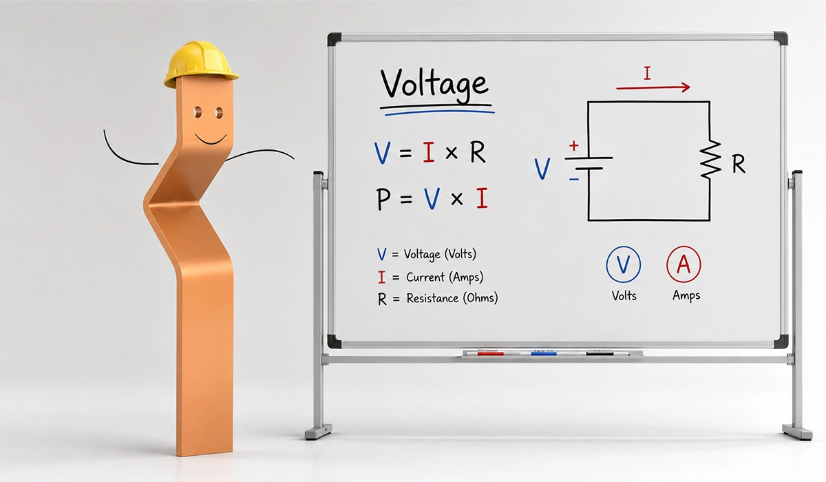
Electrical work also requires a measure of power (P), expressed in watts (W). The base relationship is P = V × I. By substituting V = I × R, you can rewrite this in two more forms that prove useful in both design and troubleshooting work.
| Formula | Use When |
|---|---|
| P = V × I | Voltage and current are known |
| P = I² × R | Current and resistance are known |
| P = V² ÷ R | Voltage and resistance are known |
Together, these equations form what many texts call the Ohm’s Law wheel, or the PIV relationships. For example, a 12 V circuit drawing 2 A dissipates P = 12 × 2 = 24 W.
This calculation matters when you choose resistors and other components. A part rated below the calculated dissipation will overheat. Conversely, an over-spec part wastes cost and board space.
Therefore, knowing how to use Ohm’s Law alongside the power formula gives engineers a complete picture of every resistive node in a design.
Where Ohm’s Law Applies — and Where It Does Not
Honest teaching also explains the limits of a rule. Understanding Ohm’s Law limitations and when it does not apply protects you from misreading non-linear components. The rule fits ohmic — linear — conductors, where the V/I ratio stays constant across a useful range. Most fixed resistors at normal temperatures behave this way.
| Component | Ohmic Behavior? | Notes |
|---|---|---|
| Fixed resistor | Yes | Linear V/I at constant temperature |
| Copper wire | Approximately yes | Low resistance, linear within normal ranges |
| Incandescent bulb | No | Resistance rises sharply with temperature |
| Diode | No | Exponential V/I characteristic |
| Transistor | No | Three-terminal, non-linear device |
| Thermistor | No | Resistance varies with temperature by design |
Diodes conduct in one direction only. Transistors switch and amplify under the control of a third terminal. Incandescent filaments heat up and change resistance during operation, while thermistors do so on purpose.
Nevertheless, the rule remains the starting point for any analysis. Engineers apply it to the resistive parts of a circuit and bring in extra tools — such as the diode equation — for the non-linear parts.
Ohm’s Law in Real-World Electrical Engineering Applications
The question of why Ohm’s Law is important in electrical engineering answers itself the moment you walk a real installation. The rule touches almost every routine task: sizing fuses and circuit breakers, choosing wire gauges, designing current-limiting resistors, and diagnosing faults on the bench or in the field.
Take overcurrent protection. The expected current through a load follows directly from V ÷ R. Designers then pick a breaker that trips above normal draw, yet below the wire’s safe limit. Likewise, wire gauge selection depends on the voltage drop along a run, which is simply I × R at the conductor’s resistance per metre.
Designing an LED current-limiting resistor uses the same single calculation. Subtract the LED forward voltage from the supply, then divide by the target current.
Finally, troubleshooting also relies on prediction. When a measured value strays far from what the rule predicts, the technician immediately suspects an open circuit, short, or degraded component.
Visit the linked website to better understand the background, standards, and practical use cases about Authoritative US code that translates basic electrical principles into protection and wiring rules.
Conclusion about Ohm’s Law
The rule remains the single most useful relationship in electrical engineering because it captures so much in one short equation. You now have the formula, the visual triangle, four worked examples, and the power extension that turns V × I into watts. You also understand where the law applies cleanly and where it does not.
For most day-to-day work, that toolkit is enough. Sizing a fuse, picking a resistor, predicting a voltage drop, or finding an open all reduce to the same V = IR backbone. As circuits grow more complex, you can layer Kirchhoff’s laws and impedance analysis on top.
However, every harder topic in electronics starts from this same foundation. Master it well, and the rest becomes far easier to learn.




Rate this article
Choose a rating from 1 to 5 stars.
No ratings yet