









If you’d rather listen than read, feel free to play the audio file below for the rest of this article.
What Does RMS Actually Mean?
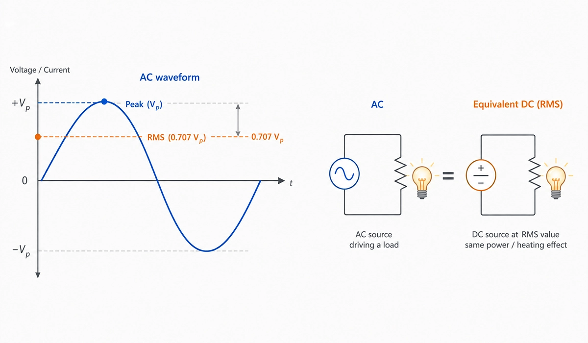
The acronym RMS stands for Root Mean Square, and it describes a three-step mathematical operation rather than a static label. First, you square every instantaneous value of the waveform. Next, you average those squared values over one full cycle. Finally, you take the square root of that mean. This sequence converts a positive-and-negative AC signal into a single equivalent DC value that delivers the same power to a resistive load.
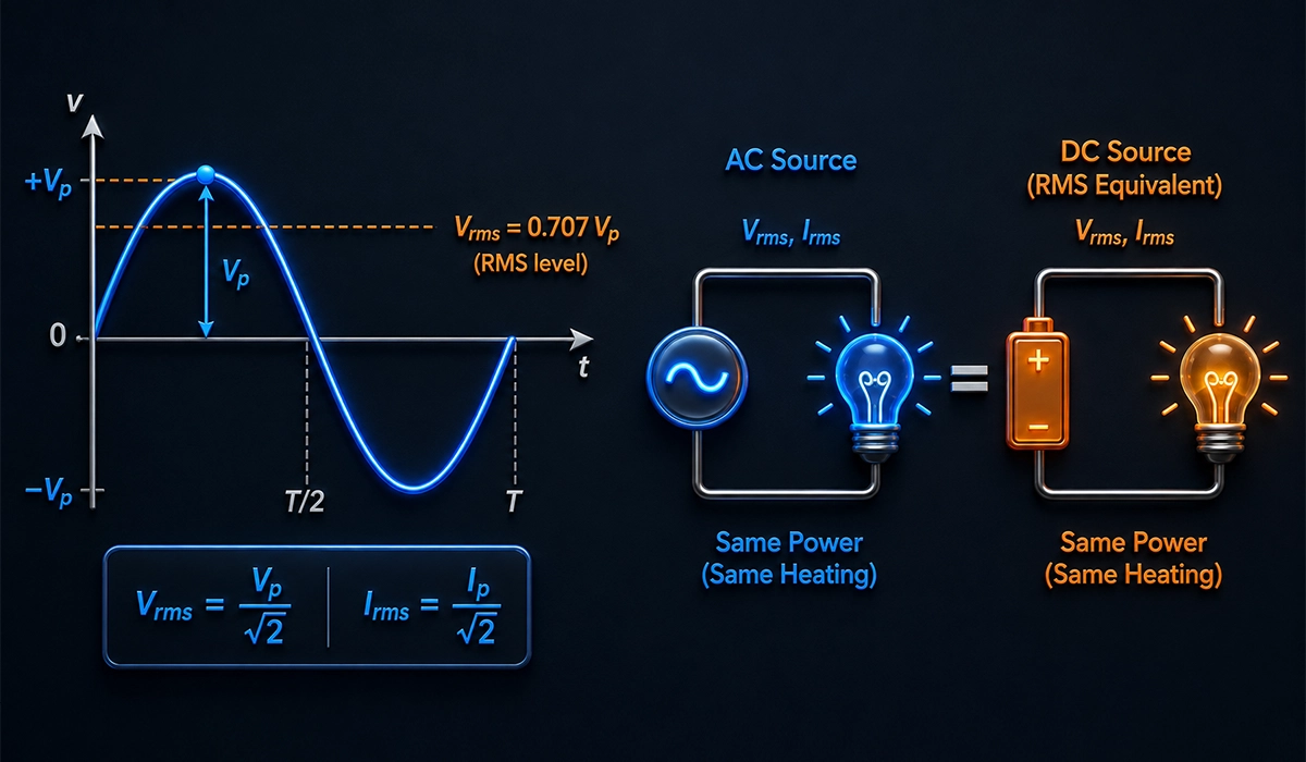
So what is RMS voltage in practice? The general RMS voltage formula for any continuous periodic signal is V_rms = √(1/T ∫₀ᵀ v²(t) dt). The integral handles arbitrary shapes, while the square root unwinds the squaring step. For a pure sine wave specifically, this AC RMS value definition simplifies to V_rms = V_peak / √2 ≈ 0.7071 × V_peak.
Why bother with this elaborate procedure? Because it answers a deeply practical question: what DC voltage would deliver the same heating effect to a resistor as this AC waveform? That heating-effect equivalence is the conceptual key to RMS Voltage and Current in AC Circuits.
In other words, RMS is the effective voltage of an alternating signal. Therefore, engineers rely on it whenever they need to predict real power transfer instead of tracking instantaneous voltage swings cycle by cycle.
Visit the linked website to better understand the background, standards, and practical use cases.
To see where RMS fits within the bigger picture of AC theory, start with our complete guide to electrical fundamentals.
Why Not Use Peak or Average Voltage Instead?
Engineers regularly ask why we do not simply label outlets with peak voltage or use the signal average. The answer cuts to the heart of why AC uses RMS values for any power-related calculation, and it shapes everything from appliance design to utility billing.
A waveform’s peak value reveals the maximum instantaneous stress on insulation, yet it tells you almost nothing about sustained energy transfer. Similarly, the arithmetic average of a symmetric sinusoid over one full cycle equals exactly zero, which would imply no power delivery at all — clearly an absurd conclusion for a heating element drawing real current.
Both peak and average measures therefore fail when you need a single number that ties directly to power dissipation. By contrast, RMS preserves the energy equivalence that engineering calculations demand. As a result, IEEE, IEC, and NEC documents almost always quote AC quantities as RMS values unless explicitly stated otherwise.
The next two subsections explore each shortcoming in detail. First, we examine why peak voltage misleads power estimates. Then we show why average voltage fails for symmetric AC signals, despite being intuitive at first glance.
For readers who want more technical depth, this reference page is a useful starting point.
Before comparing these measures further, make sure you are comfortable with the basics of voltage, current, and resistance.
Why Peak Voltage Is Misleading for Power Calculations?
Peak voltage, written V_peak or V_max, marks the highest instantaneous point on the waveform. However, AC never lingers at that peak — it constantly varies. Plugging V_peak into a DC-style power formula therefore wildly overestimates real energy transfer. Consider RMS vs peak voltage in a 170 V peak sine wave: it does not deliver the same power as a 170 V DC source, because the voltage spends most of each cycle well below 170 V. This difference between peak voltage and RMS voltage in AC circuits explains why nameplate ratings always use RMS values.
RMS ratings also underpin how supply systems are compared, as explained in our article on single-phase vs three-phase power.
Why Average Voltage Fails for AC
For any symmetric sine wave, the mathematical average across a full cycle equals zero — the positive half exactly cancels the negative half. Therefore, a zero average tells you nothing useful about heating effect or power transfer. Some meter designs use the average of the rectified signal (about 0.637 × V_peak), but that figure is not interchangeable with RMS. So in the debate of RMS vs average voltage — which one matters for power — the answer is RMS, because it preserves the squared-magnitude information that average voltage discards. This is precisely why we use RMS instead of average for AC voltage in every serious engineering context.
| Voltage Measure | Formula (Sine Wave) | Value for 170 V Peak | Represents | Used For |
|---|---|---|---|---|
| Peak Voltage (Vpeak) | Vpeak | 170 V | Maximum Instantaneous Value | Insulation Ratings, Oscilloscope Readings |
| Peak-to-Peak (Vpp) | 2 × Vpeak | 340 V | Full Vertical Swing of Waveform | Oscilloscope Display, Signal Amplitude |
| Average (Full Cycle) | 0 | 0 V | Mathematical Mean | Not Useful for AC Power |
| Average (Rectified) | 0.637 × Vpeak | 108.3 V | Mean of Absolute Values | Certain Analog Meter Designs |
| RMS Voltage | Vpeak ÷ √2 | 120.2 V | Power-Equivalent DC Value | Power Calculations, Appliance Ratings, Utility Billing |
Visit this page to learn more about the specifications, applications, and related details.
The Math Behind RMS for a Sine Wave—Step by Step
Take a household waveform written as v(t) = 170 sin(2π·60·t). The peak value, V_peak, equals 170 V; the angular frequency, ω, is 2π·60 rad/s. Now apply the integral form of the RMS formula across one full period T.
Squaring the sine produces sin²(ωt), which has a known time-averaged value of one half. As a result, the mean of v²(t) becomes V_peak² / 2 = 170² / 2 = 14 450. Taking the square root yields V_rms = √14 450 ≈ 120.2 V. So how to calculate RMS voltage from peak voltage on a sine wave reduces to a single shortcut: divide V_peak by √2.
The same logic applies to current: I_rms = I_peak / √2. Consequently, if an appliance draws 5 A peak from the mains, the equivalent steady current for heating purposes is about 3.54 A.
Here is the calculation sequence at a glance:
- Write the waveform as v(t) = V_peak · sin(ωt).
- Square it: v²(t) = V_peak² · sin²(ωt).
- Take the time average across one full period.
- Take the square root to recover V_rms.
This procedure also confirms the familiar 120 V label on every American outlet, since 170 / √2 ≈ 120.2 V matches the nominal value defined by ANSI C84.1.
Once you have V_rms, the voltage–current–resistance relationship follows directly from Ohm’s Law.
RMS and Power—The Real Reason It Matters
For a purely resistive load, the power formula collapses into the familiar DC form: P = V_rms × I_rms. Furthermore, using Ohm’s law you can rewrite it as P = I_rms² × R = V_rms² / R. This symmetry with DC analysis is the central payoff of choosing RMS values, and it is why root mean square current explained correctly transforms AC into manageable arithmetic.
Consider a 120 V RMS supply connected to a 60 Ω resistive heater. The dissipated power equals (120)² / 60 = 240 W. If you had naively used the 170 V peak figure instead, you would predict 481 W — exactly twice the true value. That kind of error would specify a relay, conductor, or breaker incorrectly.
Importantly, RMS quantities yield the average power across many cycles, not instantaneous power. Instantaneous AC power swings rapidly with the waveform, but heat, work, and torque depend on the long-run average. Therefore, average power is what actually drives equipment temperature.
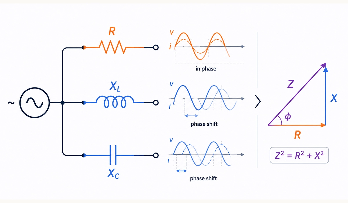
This also clarifies how RMS current relates to power dissipation: I_rms is the steady DC current that would produce the same heating in a resistor. For circuits with reactive components, the same RMS values still apply, but a power factor term enters the calculation. In practice, the use of RMS Voltage and Current in AC Circuits turns complex sinusoidal analysis into straightforward algebra.
To go deeper into these power equations and their variations, read our full breakdown of the electrical power formula.
RMS Values for Non-Sinusoidal Waveforms
The shortcut V_rms = V_peak / √2 only applies to pure sine waves. Once the waveform shape changes, the peak-to-effective relationship changes too. For a square wave at 100 percent duty cycle, V_rms equals V_peak exactly. For a symmetric triangle wave, V_rms equals V_peak / √3. Other shapes — sawtooth, pulse trains, distorted mains, PWM outputs — each carry their own RMS-to-peak ratio, often described by the crest factor.
This matters enormously in industrial settings. Variable-frequency drives, switching power supplies, dimmer circuits, and LED ballasts all produce non-sinusoidal waveforms. Standard “average-responding” multimeters calibrated for a sine wave can return readings roughly 40 percent low or 10 percent high on distorted signals.
Consequently, how to measure RMS voltage with a multimeter on modern industrial equipment requires a true RMS instrument. A true RMS meter samples the waveform, squares each sample, averages the squares, then takes the root — exactly the mathematical definition applied digitally. Manufacturers such as Fluke publish accuracy tables showing where average-responding meters fall short.
The takeaway is simple: if the load is anything other than a clean sinusoid, reach for a true RMS meter. Otherwise, the displayed reading may quietly mislead your power and current calculations.
Real-World Examples of RMS in Practice
A few concrete cases illustrate why RMS Voltage and Current in AC Circuits matters far beyond textbooks.
First, household electricity. In North America, the 120 V outlet label is an RMS value; the actual peak is roughly 170 V. In Europe and most of Asia, the 230 V outlet sits on a 325 V peak. Insulation ratings, switchgear clearances, and creepage distances in IEC standards are all sized for those peaks, even though billing relies on RMS. That is RMS voltage of household electricity explained in one sentence.
Second, appliance ratings. When a kettle is labeled “1500 W at 230 V,” engineers use the RMS voltage and the steady-state current to specify cabling and protective devices. The same applies to motor nameplates, transformer ratings, and breaker trip curves.
Third, multimeter readings. Standard AC mode reports RMS — but only correctly when the signal is sinusoidal. Distorted waveforms call for a true RMS instrument, as discussed above.
Finally, audio engineering. Amplifier and loudspeaker datasheets quote RMS power for sustained capacity, not peak burst capacity. Confusing the two values is an expensive mistake. As a result, professionals treat RMS specifications as the contractual reference number.
This reference page is useful for readers who want to study the topic beyond this article.
How to Calculate RMS Voltage—Quick Reference
This compact reference brings the key conversion factors together. For a pure sinusoidal waveform, the relationships between peak, peak-to-peak, average, and RMS values follow fixed constants.
Use V_rms = V_peak / √2 = V_peak × 0.7071 to drop from peak to effective voltage. Going the other way, V_peak = V_rms × √2 = V_rms × 1.4142. The peak-to-peak voltage doubles the amplitude, so V_pp = 2 × V_peak = V_rms × 2.8284. The same factor applies to current: I_rms = I_peak / √2 and I_peak = I_rms × √2.
These shortcuts handle every clean sinusoid you will encounter on the mains. However, if you are dealing with a different waveform shape, the general definition still holds: V_rms = √(1/T ∫₀ᵀ v²(t) dt). Numerical integration on a captured oscilloscope trace, or a true RMS instrument, will give an exact answer for arbitrary signals.
In summary, RMS vs peak voltage conversions for sinusoids depend on a single constant, √2. Memorize 0.7071 and 1.4142, keep the integral form handy for distorted signals, and you can move between domains quickly. Furthermore, this is also how digital meters internally produce their RMS readings.
For a clearer comparison, you can review the information provided on this website.
Conclusion about RMS
RMS is not an arbitrary convention; it is the only value that turns a constantly varying AC waveform into a meaningful, power-equivalent number. Without it, every appliance rating, breaker selection, and cable size would require tracking instantaneous voltage moment by moment. With it, alternating-current circuits obey the same compact relationships as DC ones — P = V × I, V = I × R, and so on. To cement the concept, hook a known resistor across a 120 V or 230 V outlet (only in a safe, instructed laboratory setting), measure with a true RMS meter, and confirm that calculated and measured power agree. From there, the foundations of RMS Voltage and Current in AC Circuits become genuinely intuitive.



Rate this article
Choose a rating from 1 to 5 stars.
No ratings yet