






If you’d rather listen than read, feel free to play the audio file below for the rest of this article.
What Is Resistance in an Electrical Circuit?
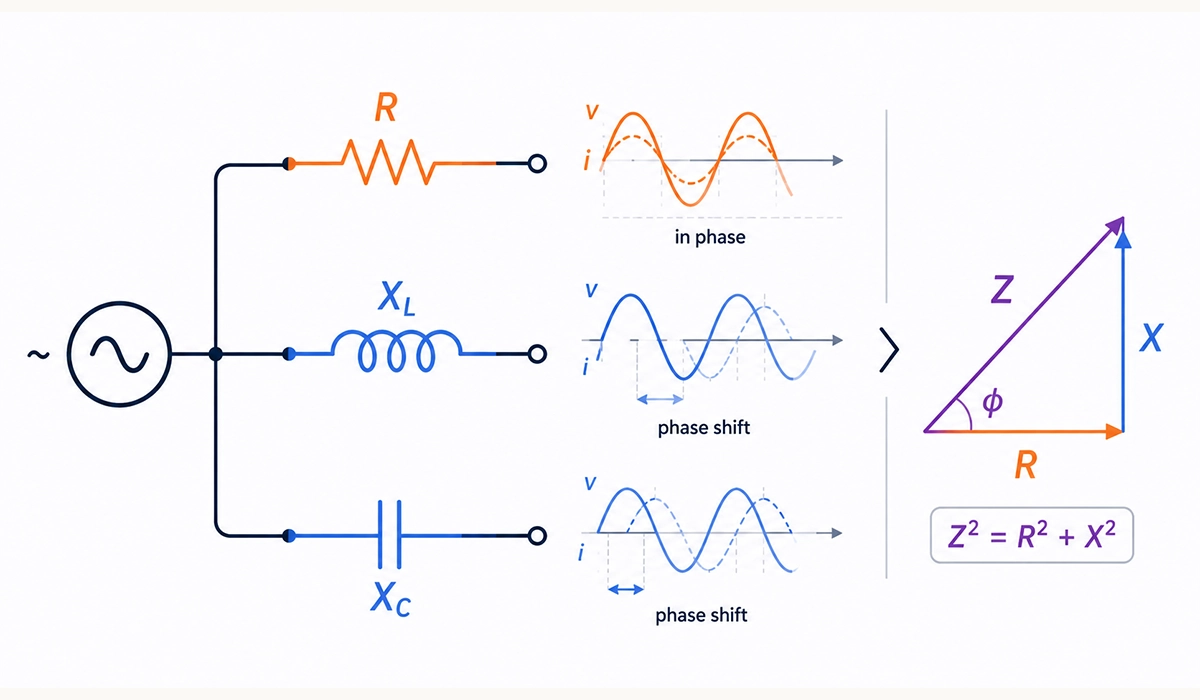
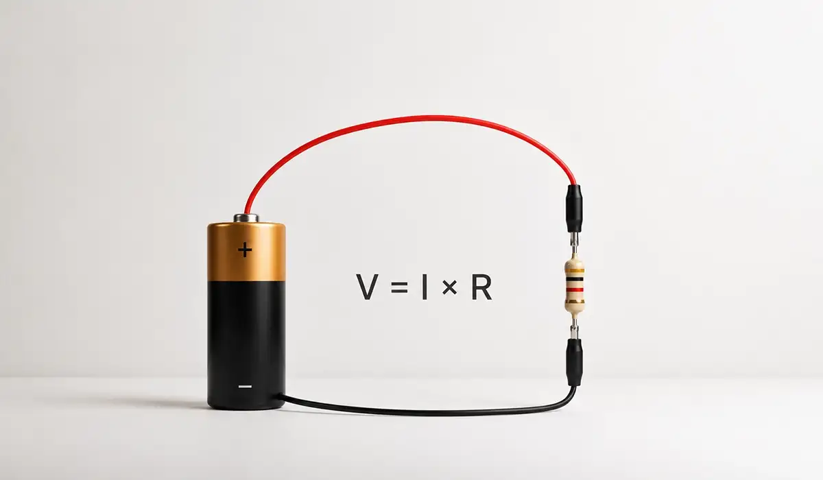
Resistance (R) describes the opposition to current flow inside a conductor, and it stays constant regardless of frequency. Furthermore, it is a purely real, ohmic quantity measured in ohms (Ω). Engineers calculate it using Ohm’s Law: V = IR, where voltage equals current multiplied by resistance.
Think of resistance as friction inside a water pipe. The narrower the pipe, the harder water pushes through, and the more energy it loses as heat. Resistors behave the same way: they dissipate electrical energy as thermal energy without storing any of it.
Unlike reactive components, a resistor does not care whether the source is DC or AC. Consequently, a 100 Ω resistor opposes 100 Ω at zero hertz and 100 Ω at one megahertz. This frequency-independent behavior makes resistance the simplest of the three concepts to model. Moreover, it forms the baseline against which we compare reactance and impedance later in this guide.
This resistive baseline connects directly to how voltage, current, and resistance interact within Ohm’s Law. For a deeper breakdown of that relationship, see our guide on Ohm’s Law.
What Is Reactance and Why Does Frequency Matter?
Reactance (X) is the opposition to current caused by energy storage elements rather than energy dissipation. While resistors waste energy as heat, capacitors and inductors store it in electric or magnetic fields, then return it to the circuit. As a result, reactance is frequency-dependent: it changes every time the source frequency shifts.
The phenomenon of frequency-dependent resistance only appears in AC circuits. In DC steady state, capacitors look like open circuits and inductors look like wires. Once you introduce alternating current, however, both components push back against changing current in opposite ways. Therefore, engineers split reactance into two categories: inductive and capacitive.
Reactance is measured in ohms, just like resistance, but it carries a phase shift that resistance does not. This phase relationship between voltage and current sits at the heart of AC circuit analysis and explains why we need complex numbers later on.
Inductive Reactance (X_L)
Inductive reactance follows the formula X_L = 2πfL, so opposition grows with frequency and inductance. Inductors resist changes in current, which causes current to lag voltage by 90°. You see this behavior in motors, transformers, relay coils, and choke filters where magnetic fields store energy temporarily.
You can check this page for more examples, explanations, and related technical resources.
Capacitive Reactance (X_C)
Capacitive reactance uses the formula X_C = 1 / (2πfC), which means opposition decreases as frequency rises. Capacitors store charge in an electric field, and current leads voltage by 90°. Engineers exploit this property in coupling capacitors, decoupling networks, power factor correction banks, and high-pass filter stages.
Comparison of Resistance and Reactance Components
| Property | Resistance (R) | Inductive Reactance (XL) | Capacitive Reactance (XC) |
|---|---|---|---|
| Symbol | R | XL | XC |
| Unit | Ohm (Ω) | Ohm (Ω) | Ohm (Ω) |
| Frequency Dependence | None | Increases with f | Decreases with f |
| Phase Shift | 0° | +90° (Current Lags) | −90° (Current Leads) |
| Energy Behavior | Dissipates as Heat | Stores in Magnetic Field | Stores in Electric Field |
| Example Components | Resistors | Inductors, Coils | Capacitors |
Visit the linked website to better understand the background, standards, and practical use cases.
Because reactance behaves so differently from resistance, it helps to revisit the basic distinction between voltage, current, and resistance first. Our article on voltage, current, and resistance covers that foundation in detail.
What Is Impedance? The Complete Picture
Impedance (Z) represents the total opposition to AC current flow, combining resistance and reactance into one complex quantity. Engineers express it as Z = R + jX, where R is the real part, X is the reactive part, and j is the imaginary unit (√−1). The magnitude follows |Z| = √(R² + X²) and the phase angle is θ = arctan(X/R).
The imaginary unit j may sound abstract, but it simply tracks the 90° phase shift that reactive elements introduce. Therefore, impedance carries both a size and a direction, which is why we call it a phasor. For example, a circuit with R = 30 Ω and X = 40 Ω yields |Z| = 50 Ω at an angle of 53.13°.
In AC analysis, the impedance vs resistance vs reactance distinction lets you apply a generalized Ohm’s Law: V = IZ. This formulation handles capacitors, inductors, and resistors with one consistent framework. Consequently, complex impedance becomes the universal tool for analyzing filters, transmission lines, and power networks.
This external page provides additional insights that may help with your evaluation.
Impedance sits at the center of nearly every core electrical concept, from basic circuits to advanced power systems. To see how these ideas connect, explore our electrical fundamentals pillar guide.
Key Differences Between Impedance, Resistance, and Reactance
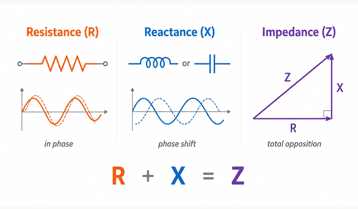
The three quantities form a clear hierarchy that clarifies the impedance vs resistance vs reactance debate. Resistance is a special case of impedance where the reactive part equals zero. Reactance is the imaginary component of impedance. Impedance itself is the complete complex quantity used in every AC analysis.
In DC circuits, only resistance matters because frequency is zero, so reactance vanishes. In AC circuits, however, all three quantities play roles depending on the components involved. A purely resistive load behaves identically in both domains, while a purely reactive load behaves like an open circuit on average but still draws current.
Here is the hierarchy at a glance:
- Resistance: real part of impedance, frequency-independent
- Reactance: imaginary part of impedance, frequency-dependent
- Impedance: full complex quantity Z = R + jX
- DC case: Z reduces to R alone
- AC case: Z reflects R, X_L, and X_C together
You can review the original source here to verify the technical details.
Since AC values constantly change over time, understanding how RMS voltage and current are calculated makes this hierarchy easier to apply in practice. Learn more in our guide to RMS voltage and current.
How Impedance Changes with Frequency
Impedance shifts dramatically as the source frequency moves. At low frequencies, capacitors block current while inductors pass it freely. At high frequencies, the roles reverse: inductors block and capacitors conduct. Engineers exploit this behavior across audio crossovers, RF tuning circuits, and antenna matching networks.
Resonance is the special condition where X_L equals X_C, so the reactive parts cancel and impedance becomes purely resistive. In a series RLC circuit, this point produces the minimum impedance and the maximum current. Conversely, a parallel RLC circuit reaches maximum impedance at resonance, which is how tuned tank circuits select a single broadcast station.
For example, a series RLC circuit with L = 1 mH and C = 100 nF resonates near 15.9 kHz. Below that frequency, the circuit looks capacitive; above it, the circuit looks inductive. Therefore, filter designers tune R, L, and C values to place resonance exactly where they want a peak or null.
These frequency-dependent effects also show up differently across single-phase and three-phase power systems, especially in industrial settings. Read our comparison of single-phase vs three-phase power for more context.
Real-World Applications Where This Distinction Matters
Audio engineering depends heavily on impedance matching between amplifiers and speakers. A typical home speaker is rated at 4 Ω or 8 Ω, and a mismatch with the amplifier causes power loss, distortion, or thermal damage. Therefore, manufacturers standardize impedance ratings to keep transfer efficient.
Power systems use capacitor banks to counteract the inductive reactance of motors and transformers. This power factor correction reduces reactive current, lowers utility penalties, and frees up transmission capacity. As a result, large industrial facilities save measurable energy costs every month.
Radio frequency design demands precise impedance matching, usually to 50 Ω on transmission lines. Mismatches cause standing waves that reduce transmitted power and can damage equipment over time. Engineers use matching networks built from inductors and capacitors to tune impedance at specific frequencies.
Filter circuits also rely on frequency-dependent reactance. Low-pass filters use capacitors to short out high frequencies, while high-pass filters use them to block DC. Combined, these elements shape signals in everything from medical sensors to industrial control systems.
Power factor correction is one of the most practical outcomes of managing reactance in real industrial systems. For a closer look at how this works, check out our guide on power factor.
Common Misconceptions About Impedance and Resistance
Many engineers and students confuse the impedance vs resistance vs reactance relationship. The first myth claims impedance and resistance are interchangeable. In reality, resistance is real and frequency-independent, while impedance is complex and frequency-dependent. They only match when reactance equals zero.
Another misconception suggests that higher impedance always means lower current. However, this depends on frequency and the phase relationship. A circuit with high impedance at one frequency may have low impedance at another, especially near resonance points.
Some learners assume reactance wastes energy like resistance does. In fact, reactance stores energy and returns it each cycle, which is why ideal inductors and capacitors dissipate nothing. Finally, people sometimes claim Ohm’s Law fails in AC circuits. It applies fully, but you must use complex values: V = IZ instead of V = IR.
Many of these misconceptions come from overlooking how power itself is calculated in AC circuits. Our breakdown of the electrical power formula clears up that confusion.
Conclusion about Impedance vs Resistance vs Reactance
The hierarchy is straightforward once you see it: resistance is a subset of impedance, reactance is the frequency-sensitive component, and impedance is the unified concept that governs every AC analysis. In DC circuits, you only need R. In AC circuits, you need Z to capture the complete picture. Therefore, mastering the impedance vs resistance vs reactance distinction unlocks confident filter design, power factor correction, and signal integrity work. Try calculating Z for a simple series RLC circuit at three different frequencies to see how the magnitude and phase shift in practice. For deeper study, explore related topics like calculating impedance in series and parallel networks or understanding power factor in industrial AC systems.


Rate this article
Choose a rating from 1 to 5 stars.
No ratings yet