




.svg)






For your convenience, if you prefer listening, you can listen to the rest of this article via the audio file below.
Voltage, Current, and Resistance Explained: What They Mean and How They Relate
Voltage, current, and resistance form the first layer of Electrical Fundamentals because they describe what pushes charge, how much charge moves, and what restricts that movement. Voltage is electric potential difference. Current is the flow rate of electric charge. Resistance is the opposition that a conductor or component presents to that current. The practical question, “what is the relationship between voltage current and resistance,” leads directly to Ohm’s Law. In basic form, higher voltage pushes more current through the same resistance, while higher resistance limits current for the same voltage.
A water pipe analogy helps once. Voltage acts like pressure, current acts like flow rate, and resistance acts like pipe restriction. However, electrical systems also include field effects, insulation limits, heating, and AC phase behavior, so the analogy has limits. In real circuit analysis, engineers use SI units: Volt (V), Ampere (A), and Ohm (Ω). These units allow consistent electrical formulas and calculations across batteries, control circuits, industrial feeders, and power distribution systems.
For more information read this.
| Quantity | Symbol | SI Unit | Measuring Instrument | Typical Values |
|---|---|---|---|---|
| Voltage | V or U | Volt (V) | Voltmeter | 1.5 V battery to 400 V three-phase |
| Current | I | Ampere (A) | Ammeter / clamp meter | mA signal current to kA fault current |
| Resistance | R | Ohm (Ω) | Ohmmeter / multimeter | mΩ cable resistance to MΩ insulation resistance |
What Is Voltage and How Is It Measured?
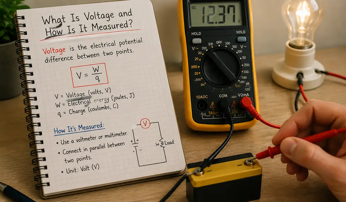
Voltage is electric potential difference between two points. It tells us how much energy each unit of charge can gain or lose as it moves through a circuit. A 1.5 V cell, for example, provides a small potential difference for portable electronics. A 230 V AC supply provides a much higher potential difference for residential loads. In many European low-voltage systems, 400 V line-to-line three-phase supply supports industrial motors and distribution boards, aligning with standard-voltage references such as IEC 60038.
Want to dive deeper? Read this article.
Engineers measure voltage across two points, not through a component. Therefore, a voltmeter connects in parallel with the element or supply being checked. For example, if a technician measures 24 V DC between the positive and negative terminals of a control power supply, the meter displays the potential difference available to drive current through connected loads. High voltage with no load does not guarantee correct performance; however, it shows the source can create the required electrical pressure.
What Is Current and How Is It Measured?
Current is the rate at which electric charge flows through a conductor. Its SI unit is the Ampere (A). A current of 1 A means 1 Coulomb of charge passes a point each second. In direct current fundamentals, current flows in one steady direction after the circuit closes. In alternating current fundamentals, current reverses direction periodically, usually as a sinusoidal waveform in power systems.
Conventional current direction runs from positive to negative, while electron flow moves from negative to positive in metallic conductors. Technicians still use conventional current in most diagrams, protection studies, and control schematics. To measure current, an ammeter connects in series with the load, so all load current passes through the meter. For higher currents, a clamp meter measures the magnetic field around a conductor without opening the circuit. This method improves safety and speed during panel testing.
Example: A 24 V DC relay coil has a rated resistance of 600 Ω. Current equals I = V / R = 24 / 600 = 0.04 A. Therefore, the coil draws 40 mA during operation.
What Is Resistance and What Determines It?
Resistance is the opposition a material presents to electric current. Its unit is the Ohm (Ω). Copper wire has low ohmic resistance, so it suits power cables, busbars, and machine wiring. Nichrome has much higher resistance, so manufacturers use it in heating elements. Insulation materials show very high resistance, often measured in megaohms, because they must block leakage current.
Four factors determine conductor resistance: material resistivity, length, cross-sectional area, and temperature. The basic relationship is R = ρL / A, where ρ is resistivity, L is length, and A is cross-sectional area. A longer cable increases resistance. A larger cross-section reduces resistance. Also, copper resistance rises as temperature rises, so hot cables lose more voltage and dissipate more heat.
Example: If a copper conductor has a resistance of 0.2 Ω at a given length, doubling the length raises resistance to about 0.4 Ω. Doubling the cross-sectional area lowers it to about 0.1 Ω, assuming the same material and temperature.
This data is sourced from the Engineering ToolBox, a comprehensive reference for technical calculations and engineering principles.
Ohm’s Law Explained: Formula, Triangle, and Practical Circuit Examples
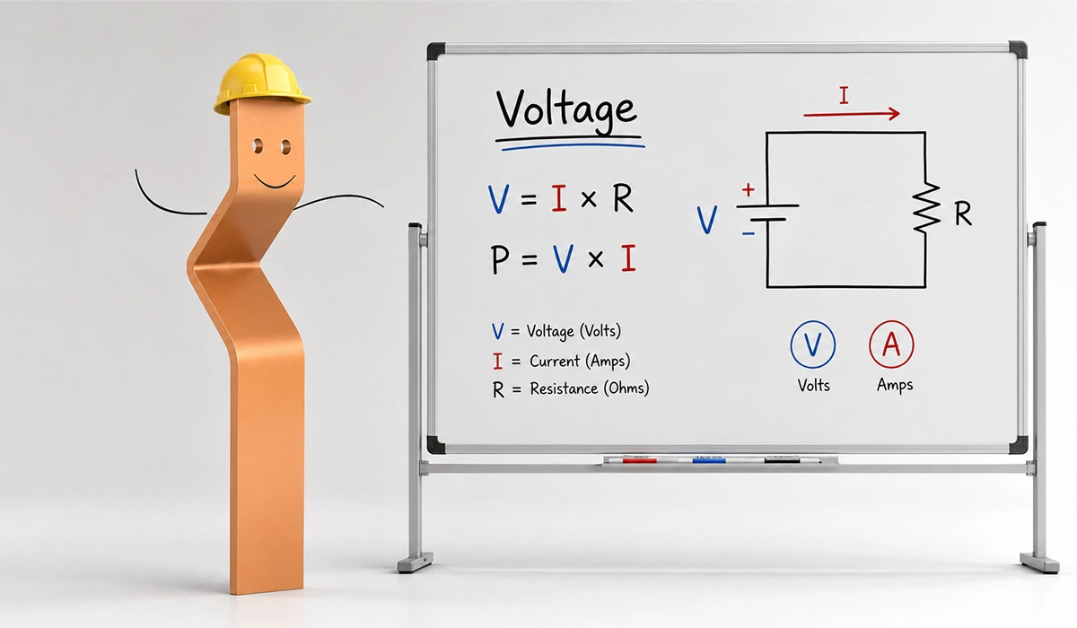
Ohm’s Law explained in practical terms: voltage, current, and resistance have a proportional relationship in an ohmic circuit. The core formula is V = I × R, where V is voltage in volts, I is current in amperes, and R is resistance in ohms. Electrical Fundamentals rely on this formula because it turns circuit behavior into a measurable calculation. With it, engineers can size resistors, estimate current draw, check voltage levels, and diagnose abnormal loads.
The Ohm’s Law triangle places V at the top and I × R below it. Cover the unknown value and read the remaining operation. Therefore, if voltage and resistance are known, use I = V / R. If voltage and current are known, use R = V / I. If current and resistance are known, use V = I × R. This answers the common field question: how to use Ohm’s Law in a real circuit.
| Known Values | Unknown | Formula to Use | Short Example |
|---|---|---|---|
| Voltage (V) and resistance (R) | Current (I) | I = V / R | 24 V / 120 Ω = 0.2 A |
| Voltage (V) and current (I) | Resistance (R) | R = V / I | 12 V / 0.5 A = 24 Ω |
| Current (I) and resistance (R) | Voltage (V) | V = I × R | 3 A × 8 Ω = 24 V |
The formulas and circuit applications explained above are sourced from established tutorials in electrical engineering.
The Ohm’s Law Formula and Its Three Forms
The three forms of Ohm’s Law solve different design questions. Use V = I × R when current and resistance are known. Use I = V / R when voltage and resistance are known. Use R = V / I when voltage and current are known. These forms support basic electrical formulas every engineer should know because they connect measured values to component behavior.
Example 1 — resistance calculation: A small DC lamp operates from 12 V and draws 0.5 A. Resistance equals R = V / I = 12 / 0.5 = 24 Ω. The lamp behaves like a 24 Ω load at that operating point.
Example 2 — current calculation: A 48 V control circuit feeds a 240 Ω load. Current equals I = V / R = 48 / 240 = 0.2 A. Therefore, the load draws 200 mA, and the power supply must support at least that current plus margin.
The calculations and methodologies demonstrated above follow standard approaches documented in professional references for DC circuit analysis.
Applying Ohm’s Law in Series and Parallel Circuits
Series and parallel circuits use the same Ohm’s Law, but they distribute voltage and current differently. In a series circuit, the same current flows through every component, and voltage drops add. Equivalent resistance equals R_total = R1 + R2 + …. For example, two resistors of 10 Ω and 20 Ω in series give R_total = 30 Ω. With a 12 V supply, current equals I = 12 / 30 = 0.4 A.
In a parallel circuit, each branch has the same voltage, and branch currents add. For two resistors, equivalent resistance equals R_total = (R1 × R2) / (R1 + R2). For example, 10 Ω and 20 Ω in parallel give R_total = 200 / 30 = 6.67 Ω. With 12 V applied, total current equals I = 12 / 6.67 ≈ 1.8 A. Therefore, parallel loads draw more current than either branch alone.
The voltage and current distribution principles illustrated above form the basis for advanced analysis of any network containing series and parallel branches.
Electrical Power Formula: How to Calculate Power in DC, Single-Phase, and Three-Phase Circuits
The electrical power formula calculates how fast a circuit converts electrical energy into heat, light, motion, or another useful output. Power uses the Watt (W), named after James Watt. In DC circuits, voltage and current stay constant, so P = V × I gives real power directly. In AC systems, phase angle matters. Therefore, single-phase and three-phase formulas include power factor when loads contain motors, transformers, inductors, or capacitors.
Electrical formulas and calculations must always match the circuit type. A DC heater, a single-phase fan, and a three-phase motor all convert energy, but they do not use the same calculation structure. Therefore, engineers must identify voltage type, current type, load behavior, and phase arrangement before applying formulas. This section also answers how to calculate electrical power in a three-phase system.
| Circuit Type | Real Power Formula | Notes |
|---|---|---|
| DC | P = V × I | No power factor needed |
| DC from resistance | P = I²R or P = V²/R | Derived from Ohm’s Law |
| Single-phase AC | P = V × I × cos φ | cos φ is power factor |
| Three-phase AC | P = √3 × VL × IL × cos φ | VL = line voltage, IL = line current |
Selecting the correct power formula based on circuit topology and load characteristics is a fundamental skill detailed in established resources for electrical professionals.
Power Calculation in DC Circuits
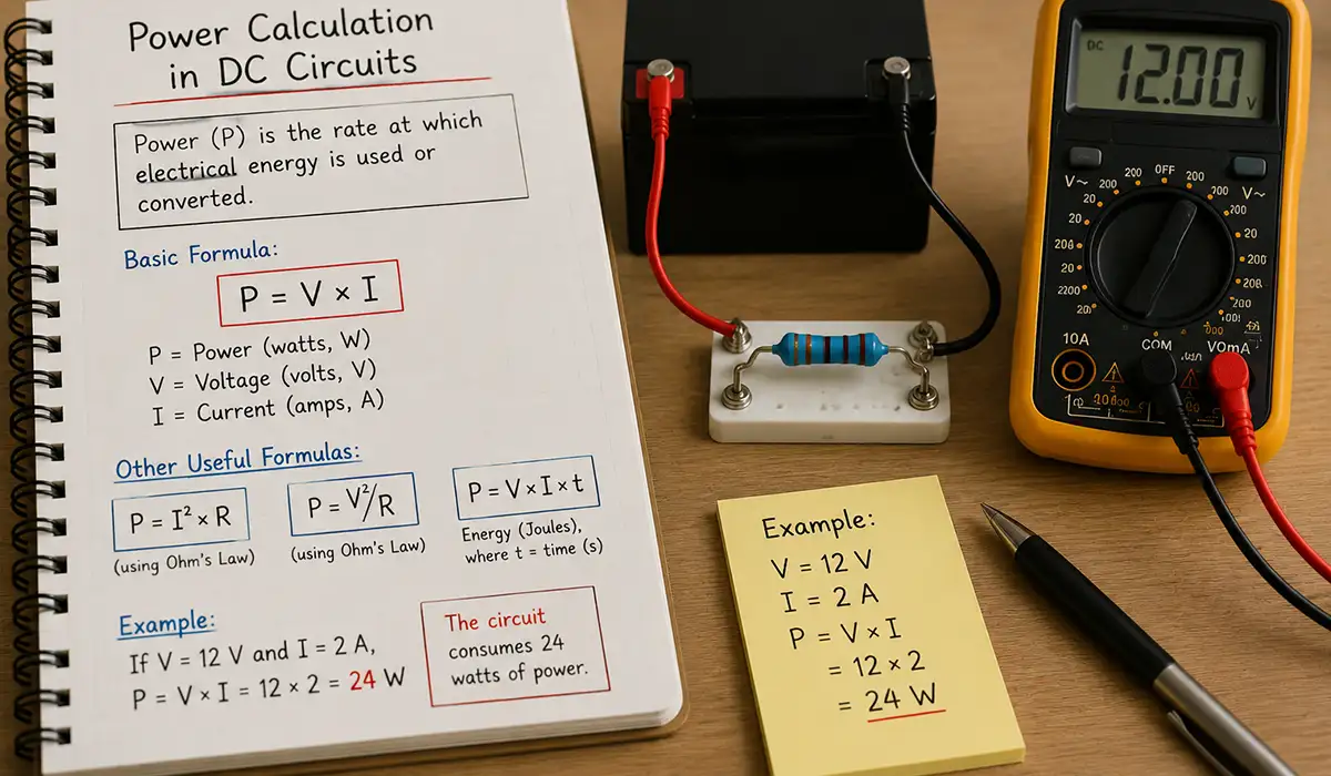
In DC circuit fundamentals, power equals voltage multiplied by current: P = V × I. This form suits loads such as DC lamps, solenoids, heaters, and electronics. Example: A 24 V DC device draws 2 A. Power equals P = 24 × 2 = 48 W. The supply must deliver at least 48 W, plus margin for starting current and losses.
Ohm’s Law creates two derived power formulas. If current and resistance are known, use Joule’s Law form: P = I²R. Example: A 5 A current flows through a 2 Ω resistor. Power equals P = 5² × 2 = 50 W. If voltage and resistance are known, use P = V²/R. Example: A 12 V supply feeds a 6 Ω load. Power equals P = 12² / 6 = 24 W.
These power calculation methods and their real-world application examples follow the principles documented in standard textbooks on DC circuit design and load analysis.
Power Calculation in Single-Phase AC Circuits
Single-phase AC power uses voltage and current, but real power also depends on phase angle. The formula is P = V × I × cos φ, where cos φ is power factor. For a pure resistive heater, voltage and current stay in phase, so power factor equals 1. For an induction motor, current usually lags voltage, so power factor falls below 1.
Example: A single-phase 230 V motor draws 8 A at 0.82 power factor. Real power equals P = 230 × 8 × 0.82 = 1508.8 W, or about 1.51 kW. Apparent power equals S = V × I = 230 × 8 = 1840 VA. Reactive power exists because the motor exchanges magnetic energy with the supply. The full distinction between apparent power reactive power real power appears in the power factor section.
These power relationships in AC circuits—where voltage and current may not align—are explained in detail within established guides on AC system performance and energy efficiency.
Power Calculation in Three-Phase AC Circuits
Three-phase power calculation uses the line voltage, line current, and power factor: P = √3 × VL × IL × cos φ. The √3 factor appears because the three phase voltages sit 120° apart. This phase geometry allows a three-phase AC system to deliver smoother power than a one-phase supply, especially to motors and heavy industrial loads.
Example: A 400 V three-phase motor draws 25 A at 0.86 power factor. Real power equals P = 1.732 × 400 × 25 × 0.86 = 14,895 W, or about 14.9 kW. This three-phase power calculation formula explained in line quantities helps panel builders choose feeders, breakers, contactors, overload relays, and power analyzers.
The relationship between line voltage, line current, power factor, and the √3 multiplier in three-phase systems ensures accurate power assessment for factory and utility-scale installations.
Single-Phase vs Three-Phase Power: Key Differences, Uses, and Industrial Implications
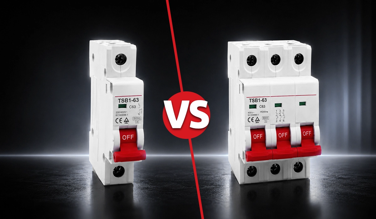
Single-phase vs three-phase power affects conductor layout, load capacity, motor performance, and installation cost. A single-phase system uses one live waveform and a neutral path in common low-voltage installations. A three-phase system uses three live conductors with waveforms displaced by 120°. In Europe, typical values include 230 V single-phase and 400 V line-to-line three-phase. In North America, common values include 120/240 V single-phase and 208 V or 480 V three-phase, depending on the service.
The difference between single-phase and three-phase power supply matters most when loads become large or motor-driven. Single-phase power delivery pulsates because one waveform crosses zero twice each cycle. Three-phase power delivers a more constant rotating magnetic field, so motors start better, run smoother, and carry heavy loads more efficiently. However, three-phase wiring adds complexity, protection requirements, and load balancing duties.
| Criterion | Single-Phase | Three-Phase |
|---|---|---|
| Number of live conductors | 1 | 3 |
| Typical voltage in Europe | 230 V | 400 V line-to-line |
| Power delivery | Pulsating | More constant and smooth |
| Efficiency for large loads | Lower | Higher |
| Typical use | Residential, small commercial | Industrial, motors, large loads |
| Motor starting | Limited | Superior |
| Wiring complexity | Simple | More complex |
| Load balancing | Minimal | Important across phases |
For small lighting, socket, and office loads, single-phase supply usually works well. For motors, compressors, CNC equipment, busbar machinery, pumps, HVAC plant, and large panel loads, three-phase supply normally gives better current distribution and better motor performance. Therefore, industrial engineers choose three-phase AC when load size, starting torque, and efficiency justify the extra design effort.
Proper conductor sizing, protection coordination, and load balancing strategies differ fundamentally between single-phase and three-phase systems, as explained in established specifications for facility electrification.
Power Factor Explained: Formula, Power Triangle, and Why It Matters in Industrial Systems
Power factor in electrical systems is the ratio of real power to apparent power: PF = P / S. Real power, measured in kW, performs useful work. Apparent power, measured in kVA, represents the total supply capacity required. In a resistive load, voltage and current stay aligned, so power factor approaches 1. In inductive loads, current lags voltage, so the supply must deliver extra current that does not become useful shaft power, heat, or light.
This is why the question “what is power factor and why does it matter industrially” has a commercial answer as well as a technical one. Low power factor raises current for the same kW output. Higher current increases I²R cable losses, transformer loading, voltage drop, and thermal stress. Utilities may also charge penalties or demand fees when facilities draw high kVA for relatively low kW.
| Power Type | Symbol | Unit | Description |
|---|---|---|---|
| Real power | P | W / kW | Useful work done by the load |
| Reactive power | Q | VAR / kVAR | Stored and released by inductors or capacitors |
| Apparent power | S | VA / kVA | Total power supplied by the source |
| Power factor | PF | Dimensionless, 0–1 | Ratio of P to S, often cos φ |
The distinction between real, reactive, and apparent power—and their financial impact on industrial operations—is explained in comprehensive documentation on AC system optimization and demand management.
Real Power, Reactive Power, and Apparent Power
Real power P performs useful work. Motors convert it to mechanical output and losses. Heaters convert it to thermal output. Lamps convert it to light and heat. Reactive power Q does not perform network over a full AC cycle, but inductors and capacitors need it to build magnetic and electric fields. Apparent power S combines both and defines the supply burden.
The power triangle links these values: S² = P² + Q², and PF = P / S. Example: A machine draws 100 kW and 75 kVAR. Apparent power equals S = √ (100² + 75²) = 125 kVA. Power factor equals PF = 100 / 125 = 0.80. Therefore, the supply must carry 125 kVA to deliver only 100 kW of useful work.
Understanding why apparent power exceeds real power in AC systems with inductive or capacitive loads is crucial for proper supply specification, as detailed in technical guidance on electrical system design.
What Causes Low Power Factor and Its Industrial Consequences?
Industrial systems often suffer low power factor because they contain induction motors, transformers, welding machines, fluorescent lighting ballasts, and drives running at partial load. Inductive loads create lagging power factor because current lags voltage. Some capacitive networks create leading power factor, but industrial plants more often fight lagging conditions.
The consequences scale quickly. Suppose a plant needs 100 kW. At 1.0 PF, apparent power equals 100 kVA. At 0.75 PF, apparent power equals S = P / PF = 100 / 0.75 = 133.3 kVA. Therefore, the same useful load demands 33.3% more supply capacity. That extra current can heat cables, increase line drop, overload transformers, reduce spare capacity, and raise utility charges.
The financial penalties from utilities and the operational constraints imposed by low power factor motivate proactive assessment and mitigation of lagging reactive loads across industrial installations.
How Power Factor Is Corrected in Industrial Facilities?
Facilities improve power factor by adding controlled reactive power that offsets the inductive demand of motors and transformers. Capacitor banks supply leading reactive power, which counteracts lagging reactive power. Engineers can install correction at the load, at a motor control center, at a distribution panel, or near the main supply point.
Fixed capacitor banks suit stable loads. Automatic capacitor banks switch steps in and out as load changes. Dynamic systems handle fast-changing loads and harmonic-sensitive networks. Example: If a plant runs at 100 kW and 0.80 PF, apparent power equals 125 kVA. To improve to 0.95 PF, apparent power becomes 100 / 0.95 = 105.3 kVA. The supply current falls by about 15.8%, reducing thermal stress and freeing transformer capacity.
The decision to install correction at equipment level, motor control centers, or main distribution points involves trade-offs in cost, control complexity, and performance—factors addressed in comprehensive references for electrical system retrofit.
Voltage Drop Explained: Causes, Effects, and Why It Matters in Electrical Systems
Voltage drop in electrical circuits is the reduction in voltage along a conductor due to current flowing through conductor resistance and impedance. A cable may look like a simple connection on a drawing, but it behaves like a small series impedance in the field. As load current rises or cable length increases, the receiving-end voltage falls. This affects motors, heaters, lighting, control power supplies, sensors, and variable-speed drives.
Voltage drop matters because equipment needs voltage close to its rated value. Motors may draw more current and run hotter. Lighting can dim. Contactors may chatter. Sensitive electronics may fault. Cable losses also increase energy cost because lost power turns into heat. Therefore, cable sizing and voltage drop calculations form a practical bridge between circuit theory and safe installation design.
| Circuit Type | Voltage Drop Formula | Notes |
|---|---|---|
| DC / single-phase approximation | VD = 2 × I × R × L | Factor of 2 accounts for outgoing and return path |
| Three-phase approximation | VD = √3 × I × R × L | L is one-way cable length |
| Percentage voltage drops | VD% = (VD / Vsupply) × 100 | Many designs target about 3–5%, depending on circuit type |
| Loss check | Ploss = I²Rtotal | Shows heat produced in conductors |
The trade-off between cable cost and voltage drop margin requires careful analysis of load profiles and design constraints, explained in authoritative standards for electrical system installation and maintenance.
The Voltage Drop Formula and How to Use It
The basic DC idea is VD = I × R. For a two-wire DC or single-phase circuit, designers often use VD = 2 × I × R × L, where R is resistance per meter and L is one-way length. For a balanced three-phase circuit, a simplified resistive formula is VD = √3 × I × R × L. More detailed AC calculations include reactance and power factor, especially for long feeders and larger motors.
Here is how to calculate voltage drop in a cable run. Example: A three-phase motor draws 20 A from a 400 V supply through a 50 m one-way cable. Assume conductor resistance is 0.006 Ω/m. Voltage drop equals VD = 1.732 × 20 × 0.006 × 50 = 10.39 V. Percentage drop equals VD% = 10.39 / 400 × 100 = 2.6%. This voltage drop calculation formula for cable sizing suggests the cable is acceptable if the project limit allows up to 3% or 5%.
The distinction between simplified resistive formulas and detailed AC calculations including reactance and power factor is clarified in technical guidance for long feeders and heavy motor loads.
Common Causes of Excessive Voltage Drop
Excessive voltage drop usually starts with undersized conductors. A smaller cross-sectional area increases resistance and loss. Long cable runs create the same problem because resistance accumulates with length. High load current raises the drop directly, so motor starting, overload, and future expansion can expose weak feeder design.
Poor connections also cause local voltage loss and heating. Loose terminals, oxidized joints, weak crimps, and overloaded busbar taps add resistance where designers did not intend it. High ambient temperature makes the issue worse because copper resistance rises with temperature. Therefore, engineers reduce voltage drop by increasing conductor size, shortening runs, balancing loads, improving terminations, and verifying current after commissioning.
Poor terminal quality, loose connections, and oxidized joints can silently degrade system performance and create local heating hotspots, issues addressed in inspection and commissioning procedures under IEC installation codes.
Impedance vs Resistance vs Reactance: What’s the Difference in AC Circuits?
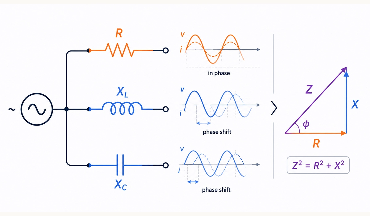
In DC circuits, resistance is the main opposition to steady current. In AC circuit analysis, two additional effects appear: inductive reactance and capacitive reactance. Resistance dissipates energy as heat. Reactance stores and returns energy through magnetic or electric fields. Impedance combines resistance and reactance into total AC opposition. This is the difference between impedance resistance and reactance in AC circuits.
The distinction matters because AC loads rarely behave like pure resistors. Motors contain windings, so they create inductive reactance. Capacitor banks create capacitive reactance. Cables contain resistance, inductance, and capacitance. Transformers include winding resistance and magnetizing reactance. Therefore, industrial calculations often require impedance, not just resistance, especially for motors, transformers, short circuit current, and cable voltage loss.
| Quantity | Symbol | Formula | Frequency Dependence | Phase Effect |
|---|---|---|---|---|
| Resistance | R | R = V / I | None in ideal model | Voltage and current in phase |
| Inductive reactance | XL | XL = 2πfL | Increases with frequency | Current lags voltage by 90° in ideal inductor |
| Capacitive reactance | XC | XC = 1 / (2πfC) | Decreases with frequency | Current leads voltage by 90° in ideal capacitor |
| Impedance | Z | Z = √(R² + X²) | Depends on R, L, C, and f | Phase angle between 0° and ±90° |
Practical AC circuit design and protection coordination require impedance calculations rather than resistance alone, particularly when assessing motor starting, fault current, and feeder behavior.
Resistance in AC Circuits — What Stays the Same
Pure resistance behaves the same in AC and DC in one important way: voltage and current stay in phase. When voltage reaches its positive peak, current also reaches its positive peak. When voltage crosses zero, current crosses zero. The resistor converts electrical energy into heat, so it consumes real power.
Example: A 230 V RMS heater has 46 Ω resistance. Current equals I = V / R = 230 / 46 = 5 A. Power equals P = V × I = 230 × 5 = 1150 W. Because the load is resistive, power factor equals 1, and apparent power also equals 1150 VA. This same calculation would fail for a motor unless we included phase angle and power factor.
The consistency of resistive behavior across DC and AC systems, where Ohm’s Law applies directly and power equals V × I without power factor correction, is detailed in foundational materials on AC waveforms.
Inductive Reactance and Capacitive Reactance
Inductive reactance is the opposition an inductor presents to AC current. It follows XL = 2πfL, where f is frequency and L is inductance. As frequency rises, inductive reactance rises. Example: A 0.1 H coil at 50 Hz has XL = 2 × π × 50 × 0.1 = 31.4 Ω. In an ideal inductor, current lags voltage by 90°.
Capacitive reactance is the opposition a capacitor presents to AC current. It follows XC = 1 / (2πfC). As frequency rises, capacitive reactance falls. Example: A 100 µF capacitor at 50 Hz has XC = 1 / (2 × π × 50 × 0.0001) = 31.8 Ω. In an ideal capacitor, current leads voltage by 90°. This leading behavior allows capacitor banks to improve lagging power factor.
The mathematical relationship between frequency, inductance or capacitance, and resulting reactance is systematically covered in AC circuit analysis resources addressing resonance, impedance, and dynamic system behavior.
Impedance — The Total Opposition in AC Circuits
Impedance Z is the vector combination of resistance and reactance. Its unit is also the Ohm, but it carries phase information. In a simple circuit, magnitude can be calculated as Z = √ (R² + X²), where X is net reactance. If inductive reactance exceeds capacitive reactance, the circuit acts net inductive. If capacitive reactance exceeds inductive reactance, it acts net capacitive.
Example: A coil has 10 Ω resistance and 31.4 Ω inductive reactance. Impedance magnitude equals Z = √ (10² + 31.4²) = 32.95 Ω. If a 230 V RMS supply feeds it, current equals I = V / Z = 230 / 32.95 = 6.98 A. The current lags voltage because inductive reactance dominates. This phase angle affects motor power calculation, transformer loading, and cable sizing.
The impedance angle, derived from the ratio of reactance to resistance, directly influences power factor, current waveform, and energy distribution in AC network calculations at all voltage levels.
RMS Voltage and Current Explained: Why AC Values Are Expressed This Way
AC voltage and current constantly change. Therefore, when an engineer says “230 V AC,” the number does not mean the waveform always equals 230 V. It means 230 V RMS voltage. RMS voltage and current express the effective value of an AC waveform. In simple terms, RMS gives the equivalent DC value that would produce the same heating effect in a resistive load.
This answers why is AC voltage expressed as RMS value. Engineers care about power delivery, heating, insulation stress, and equipment rating. RMS values make AC power formulas usable because a 230 V RMS AC supply heats a resistor like 230 V DC would. However, peak voltage still matters for insulation, semiconductor rating, surge protection, and dielectric testing.
| AC Value Type | Relationship to Peak | Example in 230 V RMS System |
|---|---|---|
| Peak voltage | Vpeak = VRMS × √2 | ≈ 325 V |
| RMS voltage | VRMS = Vpeak / √2 | 230 V |
| Average rectified sine value | Vavg = Vpeak × 0.637 | ≈ 207 V |
| Peak-to-peak voltage | Vpp = 2 × Vpeak | ≈ 650 V |
The distinction between RMS, peak, and average AC values and their practical applications in equipment rating, insulation design, and power calculations are thoroughly covered in technical tutorials on AC waveform analysis.
What RMS Means and How It Is Calculated?
RMS means Root Mean Square. Mathematically, the process squares instantaneous values over a cycle, calculates their mean, and then takes the square root. For a sine wave, the key relationship is VRMS = Vpeak / √2. Rearranged, Vpeak = VRMS × √2. This relationship applies to sinusoidal voltage and current.
Example: A 230 V RMS supply has a peak voltage of Vpeak = 230 × 1.414 = 325.2 V. Peak-to-peak voltage equals Vpp = 2 × 325.2 = 650.4 V. Therefore, a device connected to 230 V AC must not only deliver rated power at 230 V RMS; it must also withstand about 325 V peak during normal sine-wave operation.
The mathematical derivation of the √2 relationship for sinusoidal waveforms and its implications for device insulation and peak voltage withstand requirements are explained in foundational textbooks on AC circuit theory.
Why RMS Values Are Used in Electrical Engineering Practice?
RMS values allow engineers to use familiar power formulas for AC circuits. For a resistive load, P = VRMS × IRMS. Example: A heater draws 10 A RMS from a 230 V RMS supply. Power equals P = 230 × 10 = 2300 W. This matches the heating effect that 230 V DC and 10 A DC would create in the same resistance.
Most standard multimeters and panel meters display RMS values for AC measurements. True-RMS instruments improve accuracy when waveforms are distorted by drives, rectifiers, or electronic power supplies. Peak values still matter, but they answer a different question: can insulation, capacitors, and semiconductors withstand the maximum instantaneous voltage?
Designing AC systems around RMS power calculations ensures that equipment ratings, cable sizing, and transformer capacity match real heating and mechanical output, a practice reflected in standardized specifications worldwide.
Conclusion: Electrical Fundamentals
Electrical Fundamentals give engineers a reliable framework for design, troubleshooting, and industrial decision-making. Voltage pushes charge, current measures charge flow, resistance limits that flow, and power tells us how quickly energy changes form. Ohm’s Law links the first three. Power formulas then extend the same logic into DC, single-phase AC, and three-phase AC systems.
For industrial work, the basics do not stop at classroom formulas. Power factor affects transformer loading and utility costs. Voltage drop affects motor performance and cable sizing. Impedance affects AC behavior, short-circuit studies, and protection design. RMS values connect changing AC waveforms to real heating and useful power. Therefore, technicians and engineers who understand the concepts behind the equations make better choices in panels, machines, cable routes, and maintenance work.
| Concept | Practical Use | Main Formula |
|---|---|---|
| Ohm’s Law | Load current, resistance checks, voltage checks | V = I × R |
| DC power | Heaters, coils, lamps, DC supplies | P = V × I |
| Single-phase AC power | Small motors and AC loads | P = V × I × cos φ |
| Three-phase AC power | Industrial motors and feeders | P = √3 × VL × IL × cos φ |
| Power factor | kW vs kVA management | PF = P / S |
| Voltage drops | Cable sizing and load voltage | VD% = VD / Vsupply × 100 |
| RMS value | AC ratings and measurements | VRMS = Vpeak / √2 |
The bridge between classroom theory and real-world engineering success is built through systematic understanding of voltage, current, resistance, power, and the formulas that connect them—principles reinforced throughout this guide.



Rate this article
Choose a rating from 1 to 5 stars.
No ratings yet