

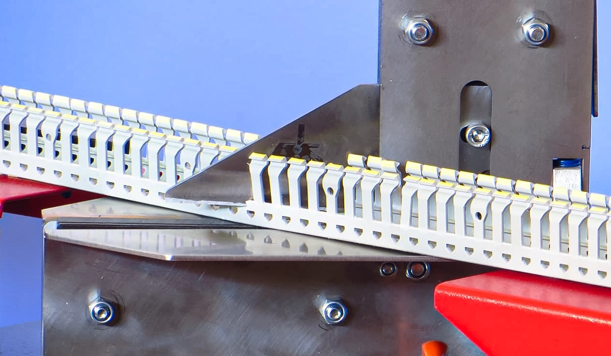





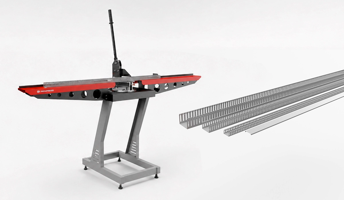
What Is Wiring Duct Cutter? A Clear Definition
Wiring duct is an open-channel cable management component that engineers mount inside electrical enclosures and control panels to organize and protect conductor runs. Unlike conduit — which fully encloses cables inside a sealed pipe — wiring duct uses an open or slotted design. That openness allows technicians to add, remove, or reroute wires without dismantling the installation. Conduit suits fixed, long-distance cable runs; wiring duct suits the dense, flexible layouts found inside panel interiors.
What is wiring duct used for in control panels? Its primary role is to consolidate individual conductors into defined routing paths. This approach reduces the risk of wire damage, cross-talk, and accidental disconnection. It also makes circuit tracing far easier during commissioning and routine fault-finding.
If you are looking for more information about Wiring Duct Cutter, it is recommended not to miss reading this article.
The term appears under several regional names, all describing the same functional product. The table below clarifies the most common equivalents in global use.
| Term | Region Commonly Used | Notes |
|---|---|---|
| Wiring Duct | North America | Most common in panel building |
| Cable Trunking | UK / Europe | Same function, different name |
| Cable Raceway | Global | Broader term; includes surface mount |
| Wire Loom Duct | Industrial Asia | Often used in OEM contexts |
Regardless of regional terminology, the core purpose of cable duct for control panels remains identical: structured, accessible, and code-compliant wire routing within an enclosure. Panel builders in North America typically encounter “wiring duct,” while European specifications use “cable trunking” — but the selection criteria and installation practices are equivalent.
For a clearer comparison about Comprehensive technical documentation on wiring duct products and panel wire management systems, you can review the information provided on this website.
Why Is Wiring Duct Important in Electrical Control Panels?
Wiring duct does far more than keep cables tidy. A well-designed wire management duct system directly affects panel reliability, safety, and long-term serviceability. Therefore, panel designers must treat duct selection and layout as a functional engineering decision — not an afterthought applied once all components are already mounted.
The core benefits fall into five distinct, measurable categories:
- Physical wire protection: Duct walls shield conductors from abrasion, vibration, and mechanical contact with adjacent components, extending insulation service life.
- Organized, traceable layouts: Defined routing channels let technicians trace any circuit from source to destination quickly and without disturbing adjacent conductors.
- Thermal management: Structured routing prevents cable bundles from blocking airflow inside the enclosure, supporting heat dissipation across the panel interior.
- Faster maintenance: Technicians access individual wires without moving adjacent circuits — critical during unplanned downtime when every minute counts.
- Regulatory compliance: Both UL 508A and IEC 61439 reference organized cable routing as a requirement for compliant panel assembly.
Additionally, a clean wiring layout reduces the likelihood of human error during panel modifications. When conductors follow a clear, labeled path through a cable duct for control panels, changes are safer and faster — especially during emergency maintenance where pressure and time constraints are highest.
For a comprehensive understanding of Improve your workflow for cutting cable management channels, we highly recommend reviewing this article.
Types of Wiring Duct — Which One Is Right for Your Application?
Duct type is one of the first design decisions a panel builder makes. Each of the main electrical wiring duct types serves a different set of application requirements — from basic wire organization to protection against heat, dust, or mechanical movement. Furthermore, the wrong type can compromise both safety and long-term maintainability in ways that are costly to correct after the panel is commissioned.
The comparison table below summarizes the key options before each type is explained in detail.
| Type | Slot Style | Best Use Case | Cover Required? |
|---|---|---|---|
| Standard Slotted | Side slots | General control panel wiring | Optional |
| Wide-Slot | Wide side slots | Thicker cable bundles | Optional |
| Solid | No slots | Dusty / dirty environments | Yes |
| Flexible | Corrugated | Moving door connections | No |
Understanding the difference between slotted and solid wiring duct — and when each is appropriate — is essential to building a panel that performs reliably across its full-service life.
This reference page is useful for readers who want to study the topic of Selection guidance and specifications for electrical wiring duct types used in industrial control panels beyond this article.
Slotted Wiring Duct
The slotted wiring duct is the most widely used type in industrial panel construction. Its side slots allow individual wires to exit the channel at any point along its length, giving designers maximum routing flexibility. Standard-slot versions suit typical control wiring; wide-slot variants accommodate larger cable bundles or thicker insulation types.
One practical limitation worth noting: without a wiring duct with cover installed, slotted duct can appear visually cluttered in a finished panel. Adding a snap-on cover address this immediately and provides an additional layer of protection for conductor runs.
For the latest available details about Specifications and selection criteria for standard and wide-slot wiring duct configurations, check the official page directly.
Solid Wiring Duct (Closed Duct)
Solid wiring duct carries no side openings. This makes it the preferred choice in environments where particulate matter, dust, or debris could enter the panel and damage wire insulation. Wires exit the duct only at the cut ends, so solid duct requires more careful layout planning at the design stage. In return, it delivers a higher level of mechanical protection and a cleaner visual finish, particularly when combined with a fitted cover.
Flexible Wiring Duct
Flexible wiring duct solves a specific routing challenge: connecting conductors between moving parts. Engineers most commonly use it between the main panel body and a hinged door or sliding module. Its corrugated construction tolerates repeated flexing without cracking or fatigue. In contrast, rigid duct would fail under continuous mechanical movement in these same locations.
Common Materials Used in Wiring Duct
Material selection for wiring duct directly affects flame retardancy, mechanical durability, environmental suitability, and regulatory compliance. Two thermoplastic materials dominate the market for standard panel applications, while metal variants serve a narrower set of specialist requirements.
Metal wiring duct — typically steel or aluminium — suits EMI-sensitive environments or installations where operating temperatures exceed the limits of thermoplastic materials. Metal duct provides electromagnetic shielding and superior thermal resistance. However, it adds both cost and weight that most standard panel builds do not justify. For the vast majority of indoor industrial control panel applications, plastic cable trunking meets all performance and compliance requirements at a significantly lower total cost.
Halogen-free thermoplastic and PVC represent the two dominant plastic categories, each suited to a distinct risk environment. Consequently, the choice between them depends on the consequence of fire in the installation area — not simply on routine operating conditions. Specifying the correct material at design stage matters greatly; retrofitting duct with a different flame rating after panel completion requires a full re-wire, an outcome that careful upfront selection avoids entirely.
Visit this page to learn more about the specifications, applications about Material specifications and flame-rating data for cable management and wiring duct products, and related details.
PVC (Polyvinyl Chloride)
PVC wiring duct dominates the industrial panel market because it combines low cost, light weight, ease of cutting, and proven performance in standard indoor environments. Most PVC duct sold for panel use carries a UL 94V-0 flame rating, meaning it self-extinguishes within ten seconds after an ignition source is removed. When comparing PVC vs metal wiring duct for industrial use, PVC suits the vast majority of applications — metal becomes necessary only in EMI-critical or extreme-temperature contexts where thermoplastic limits are exceeded.
Download this file to keep the key data, tables, and recommendations about Explains the UL 94V-0 flame rating and its application to plastic panel components and enclosure materials in one place.
Halogen-Free Thermoplastic
Halogen-free wiring duct emits far less toxic smoke when exposed to fire than standard PVC material. Regulations mandate this type in enclosed spaces where rapid evacuation is difficult — tunnels, marine vessels, hospitals, and large public buildings. Engineers must verify certification against the applicable local standard before specifying halogen-free duct, as compliance requirements vary meaningfully by jurisdiction.
For broader context, this external resource can help you continue your research on Defines halogen content limits and toxic fume emission criteria for cable and duct materials in regulated environments.
How to Size Wiring Duct — A Practical Guide
Correct duct sizing prevents overcrowding that strains insulation, blocks airflow, and complicates future panel modifications. This wiring duct sizing guide for electrical enclosures centers on one key principle: the fill ratio. Industry best practice limits conductor fills to no more than 50–60% of the duct’s cross-sectional area. Staying within this limit ensures adequate airflow, leaves reserve capacity for future wiring additions, and reduces mechanical stress on insulation from excessive bundle compression.
To apply the fill ratio in practice, calculate the total cross-sectional area of all conductors the duct must carry. For example, 30 wires each with a 4 mm diameter produce individual areas of approximately 12.6 mm² each — a total bundle area of roughly 378 mm². A 60 mm × 40 mm duct interior offers around 2,400 mm² of cross-section, so that bundle fills only 16%. In real panels, wire counts and gauges vary, so engineers apply the fill rule as a design constraint from the outset rather than a post-hoc check.
How to choose wiring duct for cable management also involves anticipating future growth. Specifying one size larger than current requirements costs very little at installation and prevents a disruptive redesign when wiring additions arise later. Best wiring duct size for control panel wiring therefore reflects both current load and realistic expansion headroom.
| Duct Width (mm) | Approx. Max Wire Count (1.5 mm² wire) | Typical Application |
|---|---|---|
| 25 mm | 10–15 wires | Small panels, PLC racks |
| 40 mm | 25–35 wires | Mid-size control panels |
| 60 mm | 50–65 wires | Large industrial panels |
| 80 mm | 80–100 wires | Main distribution panels |
This external page provides additional insights about Practical guidance on wire management, fill ratios, and duct sizing for industrial panels that may help with your evaluation.
How to Install Wiring Duct in a Control Panel
A systematic approach to installation ensures the finished panel is both mechanically secure and fully maintainable. How to install wiring duct in an electrical panel correctly begins with planning — not cutting. Poor layout decisions at this stage create wiring conflicts and clearance problems that are expensive to correct once components and DIN rails are already mounted. This wiring duct installation guide applies to standard DIN rail-based panel assemblies and covers all key steps in sequence.
- Plan the wiring layout. Identify all duct routing paths before mounting any component. Mark horizontal and vertical duct run on a panel layout drawing to confirm clearances and access.
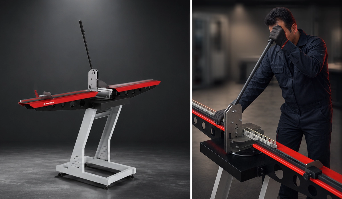
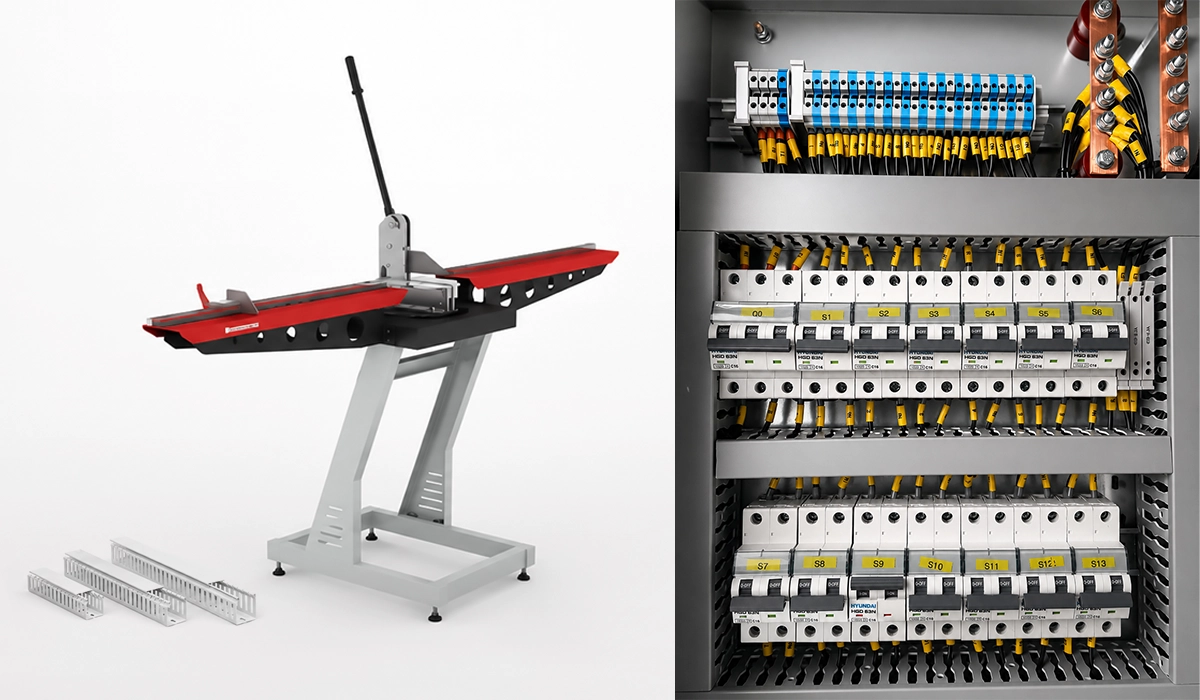
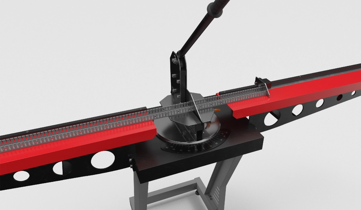
- Cut duct to length. Use a fine-tooth saw or a dedicated duct cutter for clean, square ends. Deburr cut surfaces to prevent sharp edges from damaging wire insulation.
- Mount the duct. Fix duct to the DIN rail backplate or panel base using manufacturer-specified screws or adhesive mounting clips. Confirm alignment before final tightening.
- Route conductors. Feed wires through the duct slots, leaving adequate service loops at each terminal point to allow future reconnection without placing stress on conductors.
- Install covers. Clip the wiring duct with cover panels into place after all wiring and functional testing are complete. Covers protect conductors and give the panel a professional, audit-ready finish.
- Label wires and ducts. Apply wire identification markers and duct labels per IEC 60445 terminal marking conventions to support long-term traceability and maintenance efficiency.
One critical separation rule applies throughout: never route high-voltage power conductors and low-voltage signal wires — such as 4–20 mA analogue loops or digital I/O cables — through the same duct section. This separation prevents electromagnetic interference from corrupting control signals, and both UL 508A and IEC 61439 reference this requirement explicitly.
This source can help you verify the information and continue your independent research about Industry guidance on panel assembly, DIN rail mounting, and systematic wiring organization for professional panel builders.
Conclusion about Wiring Duct
Wiring duct is one of the most practical investments a panel designer makes. It reduces build time, simplifies maintenance, supports compliance with UL 508A and IEC 61439, and protects conductors across the full-service life of the installation. Selecting the right type — slotted, solid, ventilated, or flexible — depends on the environmental conditions and routing demands of the specific application. Sizing to the 50–60% fill ratio and maintaining strict separation between power and signal conductors are the two practices that most consistently prevent field failures. Whether specifying Panduit, Phoenix Contact, or another established manufacturer, engineers who apply the principles in this guide will build panels that are safer, easier to maintain, and ready for third-party audit at any point in their service life.



Rate this article
Choose a rating from 1 to 5 stars.
No ratings yet