







If you’d rather listen than read, feel free to play the audio file below for the rest of this article.
What Is Wiring Duct and Why Does It Matter in Control Panels?
Wiring duct in control panels, also called cable trunking, wire management channel, or cable raceway, is a plastic or metal channel that organizes conductors inside an enclosure. Moreover, it routes wires from terminal blocks to components in a structured grid that protects insulation from abrasion, heat, and chafing.
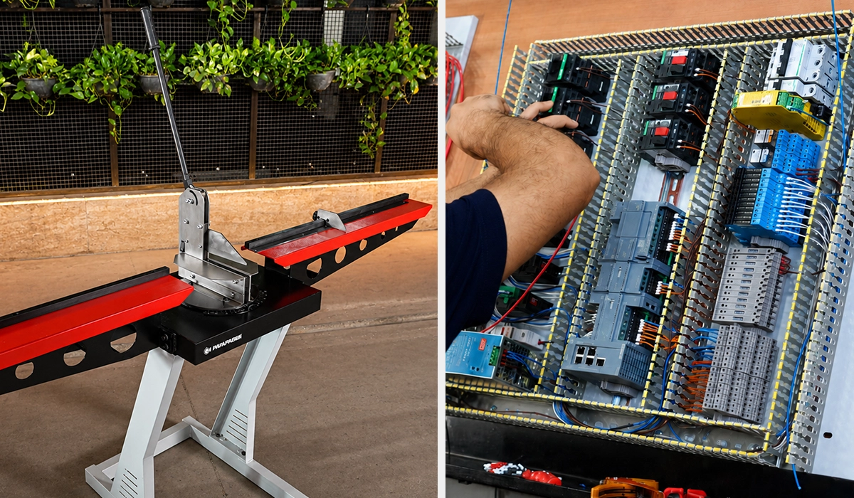
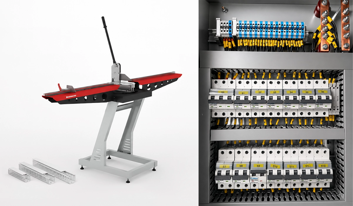
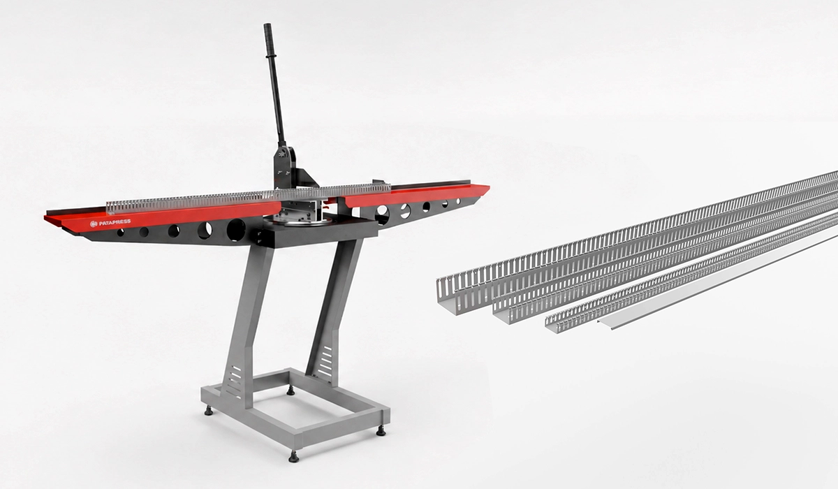
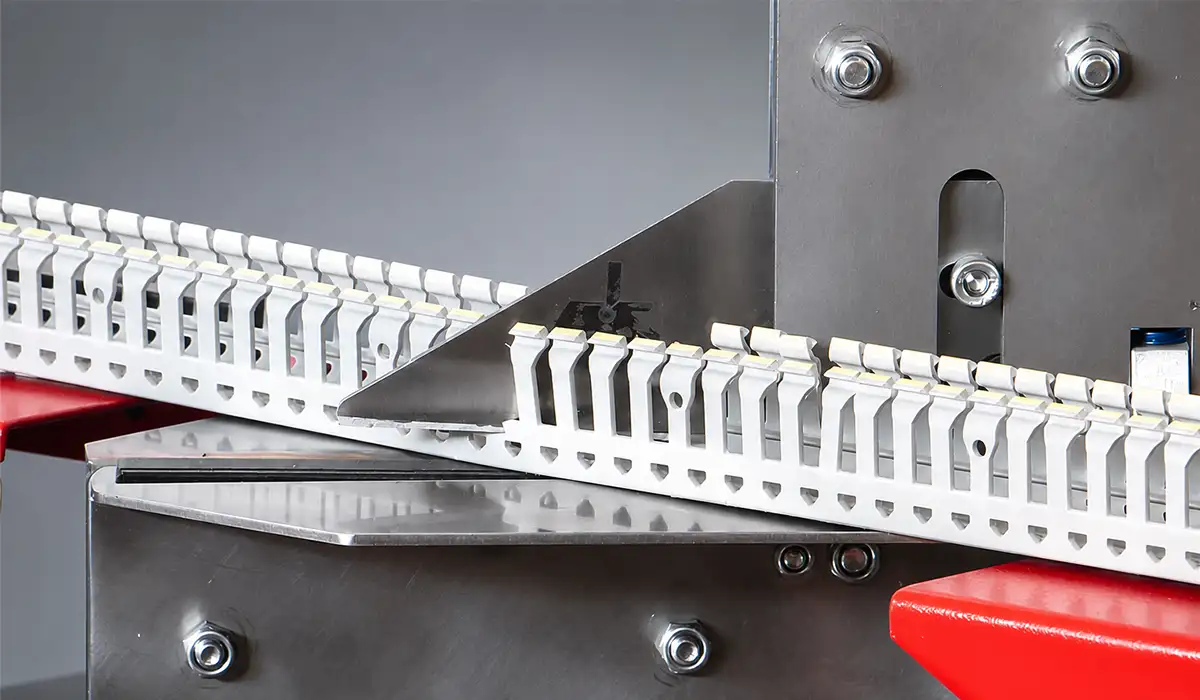
Before continuing with the article, we recommend taking a look at the wiring duct cutter to learn more about its capabilities.
The function goes beyond tidiness. First, duct walls shield conductors from sharp edges and rotating parts. Second, they create defined paths that limit electromagnetic interference between power and signal circuits. Third, they make troubleshooting faster because every wire follows a predictable route.
Standards reinforce these benefits. For instance, UL 508A specifies wiring methods, duct fill ratios, and separation rules for industrial control panels in North America. Similarly, NFPA 79 governs electrical safety on industrial machinery. Both documents push designers toward disciplined cable management in control panels.
Finally, professional appearance matters commercially. A neatly ducted panel signals quality to inspectors and end users. Therefore, treating wire duct as a core design element pays back in safety, uptime, and customer confidence.
If you want the full wiring duct meaning broken down term by term, the linked guide covers it in detail.
Types of Wiring Duct Used in Control Panels
Control panel wiring duct layout depends on choosing the right duct style for each zone. Each type solves a specific routing problem, and most panels mix two or three styles to balance density, EMI control, and movement.
See our duct types explained guide for a closer look at how each profile is built and where it fits best.
| Duct Type | Wall Style | Best Use Case | Typical Material |
|---|---|---|---|
| Slotted Wiring Duct | Open Slots with Break-Away Fingers | Dense Control Wiring, Frequent Additions | PVC |
| Solid Wall Duct | No Slots, Fully Enclosed | EMI-Sensitive Runs, Clean Power Routing | PVC or Steel |
| Flexible Duct | Corrugated, Bendable Body | Hinged Doors, Moving Parts | Nylon or PE |
| Wide-Slot Duct | Large Side Openings | Thick Power Conductors | PVC |
| Low-Profile Duct | Shallow Depth | Space-Constrained Enclosures | PVC |
Slotted duct dominates control sections because break-away fingers let installers create exit points anywhere. Solid duct, by contrast, suits power feeders and shielded runs near variable frequency drives. Flexible duct bridges hinge points without cracking. Wide-slot variants handle large bundles cleanly, while low-profile profiles rescue tight backplates.
Visit this page to learn more about the specifications, applications, and related details.
Slotted vs. Solid Wiring Duct: Which Should You Choose?
Slotted duct fits I/O zones, terminal strips, and any area that sees frequent rework. Conversely, solid duct excels for power feeders, shielded analog cables, and runs adjacent to servo drives where electromagnetic noise must stay contained. Many builders combine both styles on the same panel.
Our slotted vs solid duct comparison breaks down exactly when each style earns its place in a panel.
The full reference document is available for download to support your research.
Common Applications of Wiring Duct in Industrial Control Panels
PVC cable duct appears in nearly every panel zone, but the routing strategy changes with each zone. A well-zoned panel keeps high-energy paths separated from sensitive electronics, which protects signal integrity and operator safety.
Typical application zones include:
- Power section, where duct routes main feeds, circuit breakers, and contactor coils.
- Control section, where duct organizes PLC I/O, relay logic, and terminal block wiring.
- Communication wiring, where duct separates fieldbus, Ethernet, and analog signal cables.
- Door and sub-panel routing, where flexible duct carries cables to pushbuttons, HMIs, and pilot lights.
In the power section, builders often choose solid duct or metallic raceway to confine high-frequency emissions from drives. In the control section, slotted duct gives technicians fast access to terminals during commissioning. Communication runs benefit from dedicated channels because mixing them with motor cables introduces noise that can corrupt PLC data.
Door routing deserves special attention. Rigid duct cannot survive thousands of hinge cycles, so flexible duct or corrugated conduit becomes the safer choice. Strain relief at both ends prevents conductor fatigue.
You can visit the official website for more detailed and updated information.
Key Standards and Codes Governing Wiring Duct Use
Regulators do not leave wire duct selection to chance. Several standards intersect when designing an electrical panel wire duct system, and ignoring them creates compliance and safety risk.
UL 508A is the United States benchmark for industrial control panels. It defines wiring methods, conductor separation, and duct fill expectations. NFPA 79 sits alongside it and governs the electrical safety of industrial machinery, including color coding and wiring practices. In addition, NEC Article 409 covers field-installed industrial control panels operating at 1000 volts or less and requires short-circuit current rating labels.
Internationally, IEC 60204-1 plays the equivalent role. It addresses electrical equipment of machines up to 1000 V AC or 1500 V DC and covers wiring practices, cable selection, and enclosure rules. European panel builders also reference IEC 61439 for low-voltage switchgear assemblies.
Together, these standards push designers toward separation, identification, and disciplined routing. Always verify which document applies to your region and machine type before finalizing a duct layout.
Download the attached file to explore the complete data and supporting information.
Wiring Duct Sizing: How to Calculate the Right Capacity
Wiring duct capacity calculation for control cabinet design starts with one question. How much conductor cross-section will pass through this channel today, and how much will be added later? Industry best practice targets a 50 percent fill, which leaves room for additions and improves heat dissipation. UL 508A permits higher fills in some cases, but engineers rarely exceed roughly 75 percent because overfilled ducts trap heat and resist future rework.
Our duct width and depth guide walks through matching a channel size to your actual conductor load.
A worked example clarifies the math. Consider a 60 mm × 60 mm duct. Its internal cross-section is 3,600 mm². At a 50 percent fill, the usable area is 1,800 mm². You then sum the cross-sectional area of every conductor that will share the channel and confirm it stays within that budget.
| Duct Size (W × H) | Total Cross-Section | 50% Fill Capacity | 75% Fill Capacity |
|---|---|---|---|
| 25 × 25 mm | 625 mm² | 312 mm² | 468 mm² |
| 40 × 40 mm | 1,600 mm² | 800 mm² | 1,200 mm² |
| 60 × 60 mm | 3,600 mm² | 1,800 mm² | 2,700 mm² |
| 80 × 80 mm | 6,400 mm² | 3,200 mm² | 4,800 mm² |
These numbers translate directly into design decisions. For example, a panel with twenty 1.5 mm² control wires (each roughly 7 mm² with insulation) consumes about 140 mm² of duct space. A 40 × 40 mm duct holds that bundle comfortably at 17 percent fill, leaving generous headroom for expansion.
Common Sizing Mistakes to Avoid
Builders often undersize duct because field wiring gets added after delivery. Additionally, ignoring bend radius at duct exits crushes insulation over time. Finally, running power and control conductors through identically sized ducts wastes space in one channel and starves the other.
Layout Best Practices for Wiring Duct in Control Panels
Best wiring duct layout practices for electrical panels rest on a simple grid. Vertical ducts form the backbone along the left and right rails, and horizontal ducts cross between component rows. As a result, every wire follows a predictable path, and technicians can trace a circuit without removing covers.
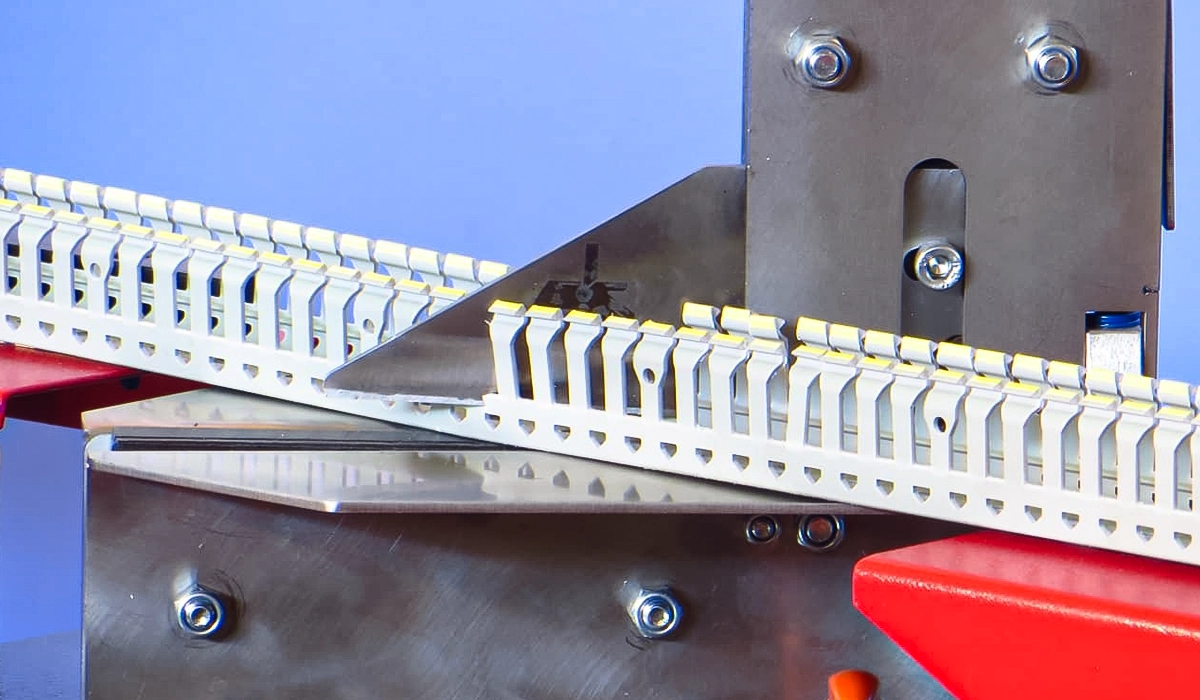
Knowing the trimming tool benefits helps installers keep every one of these cuts straight and code-compliant on site.
Separation of power and control wiring deserves equal attention. Keep 24 V DC signal conductors physically apart from 230 V AC or motor circuits, either through dedicated ducts or internal dividers. Otherwise, capacitive and magnetic coupling injects noise into PLC inputs and corrupts analog readings. Solid duct or metallic raceway near drives further reduces radiated interference.
Routing at DIN rail level also shortens conductor runs. Place horizontal duct directly above or below each row of terminals so wires drop straight into the trough. Consequently, the panel interior stays open, airflow improves, and bend radii stay generous.
Door wiring closes out the layout. Use flexible duct or corrugated conduit across every hinge, and add strain relief at both ends. In addition, leave a service loop so the door swings without tugging on conductors. These practices protect insulation through tens of thousands of door cycles.
Recommended Duct Placement Diagram Description
A typical layout shows vertical backbone ducts down both side rails, horizontal ducts framing each DIN rail row, and a separate duct path that isolates power wiring from control and signal cables. Furthermore, a flexible duct run connects the backplate to door-mounted devices, forming a clean, serviceable grid.
Material Selection: PVC, Metal, and Specialty Ducts
Material choice depends on environment, code, and risk tolerance. PVC remains the default because it cuts cleanly, costs little, and resists most chemicals found in control rooms. Most slotted wiring duct on the market ships in PVC.
Choosing the right duct trimming tool keeps those clean PVC cuts consistent from panel to panel.
Metal duct, typically aluminum or galvanized steel, suits applications that demand fire resistance, mechanical robustness, or grounding continuity. For example, marine panels and heavy industrial drives often specify steel raceway for EMC bonding. Halogen-free duct, by contrast, becomes mandatory in food processing, pharmaceutical, and rail applications because it limits toxic smoke during a fire.
High-temperature variants serve panels near heat-generating components such as resistors or transformer enclosures. In addition, low-smoke, low-toxicity duct protects personnel in enclosed spaces. Always match the duct material to the panel’s environmental rating and the customer’s industry-specific regulations.
Conclusion about Wiring Duct in Control Panels
Wiring duct in control panels is more than a routing accessory. Instead, it shapes safety, EMC performance, serviceability, and long-term reliability. Choose slotted duct for dense control zones, solid duct for power and shielded runs, and flexible duct for door wiring. Size every channel to roughly 50 percent fill, separate voltage classes, and align horizontal ducts with each DIN rail row. Furthermore, anchor the design in the right standard, whether UL 508A, NFPA 79, IEC 60204-1, or NEC Article 409, and document the choices clearly. When you treat duct layout as a first-class design decision rather than an afterthought, the panel becomes easier to build, easier to inspect, and easier to maintain for decades.


Rate this article
Choose a rating from 1 to 5 stars.
No ratings yet