







If you’d rather listen than read, feel free to play the audio file below for the rest of this article.
Why Getting Wiring Duct Size Right Is Critical
Poor wiring duct sizes create problems that appear later during testing, commissioning, or field service. Overfilled ducts squeeze insulation, trap heat, and make wire tracing slow. In contrast, a correctly sized duct gives the wire bundle space to breathe and move without mechanical stress.
Undersized duct also forces sharp bends near terminals, relays, PLC modules, and field wiring blocks. As a result, installers may exceed minimum bend radius, especially with shielded cable or flexible power wire.
In real panel work, the problem rarely stays local. One overcrowded wire channel can block access to terminals, reduce labeling clarity, and make future modifications expensive.
Therefore, cable management sizing should begin before the backplate layout is frozen. Designers should compare wire count, usable duct area, DIN rail position, and enclosure depth before they release drawings for assembly.
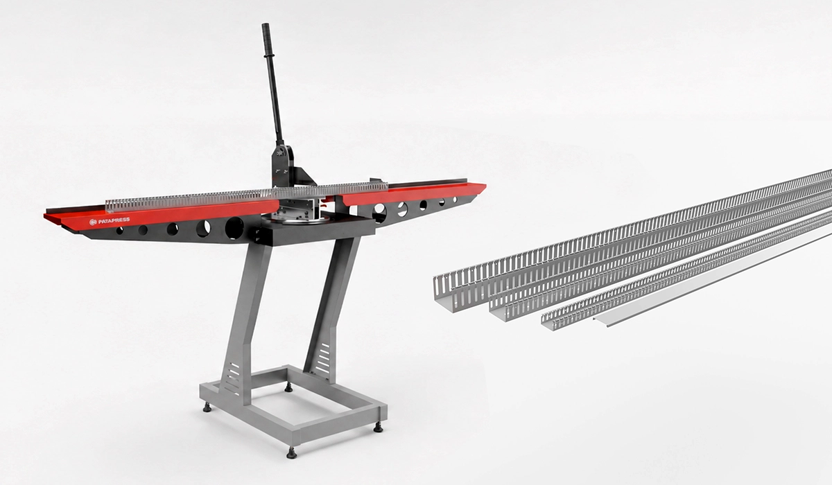
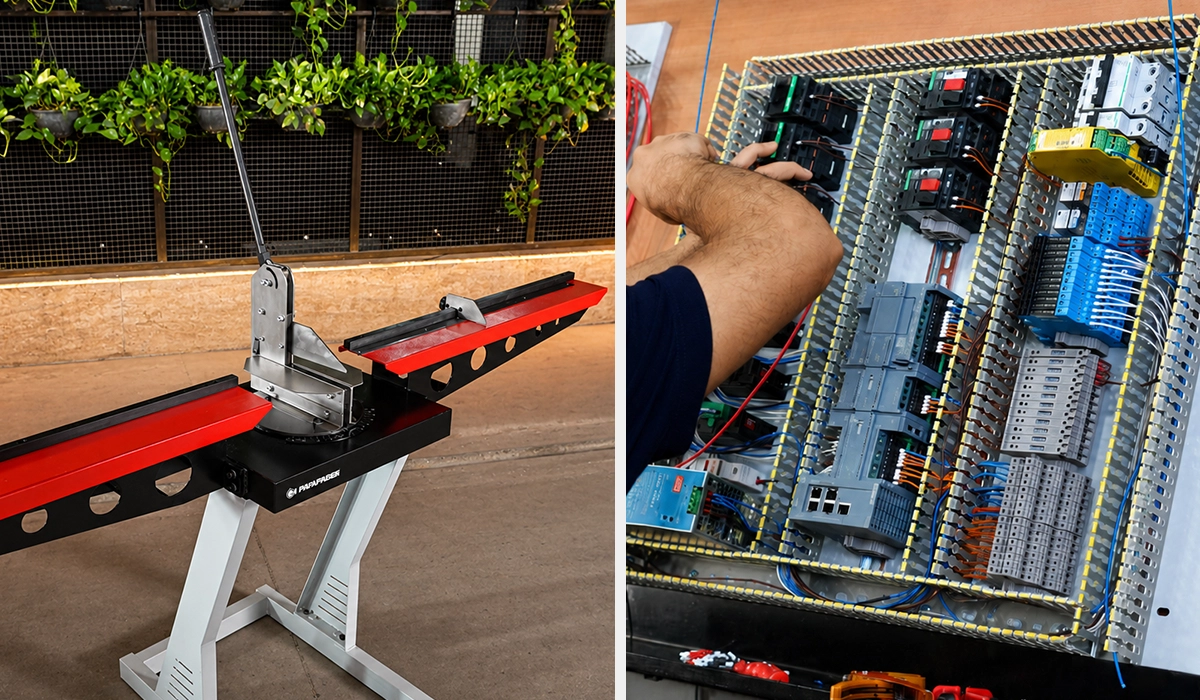
Before continuing with the article, we recommend taking a look at the wiring duct cutter to learn more about its capabilities.
The Two Dimensions That Define Wiring Duct Size
A wiring duct has two key dimensions: width and depth. Width controls how many conductors enter and exit the duct side by side. Depth controls vertical stacking and component clearance.
Together, these dimensions define the duct cross-section. The usable duct area then determines the practical fill capacity after you apply a wire fill percentage.
Designers often choose 25 mm, 40 mm, 60 mm, 80 mm, or 100 mm widths. Meanwhile, common depths range from 40 mm to 100 mm.
For control panel wire duct dimensions, do not copy one size across the full backplate. Instead, size each duct run by the wire group it carries.
For a clearer look at basic terminology, this related guide is worth a look.
| Duct Width (mm) | Duct Depth (mm) | Typical Application |
|---|---|---|
| 25 | 40 | Small panels, limited wire count |
| 40 | 60 | Standard PLC and relay panels |
| 60 | 60 | Mid-size control panels |
| 60 | 80 | Higher wire density or mixed wire gauges |
| 80 | 80 | Large industrial panels |
| 100 | 100 | Main distribution or high-density panels |
Visit this page to learn more about the specifications, applications, and related details.
Duct Width — How Much Wire Can It Hold?
Duct width is the horizontal opening of the wire channel. It usually drives capacity because wires enter, exit, and spread across the duct. For the difference between 25mm and 40mm wiring ducts, compare usable area and access space, not width alone. A 25 mm duct works in small machine panels. However, a 40 mm duct gives technicians more room for labels, finger access, and future circuits.
This downloadable guide gives you a more structured overview of the subject.
Duct Depth — How Does It Affect Installation and Clearance?
Duct depth is the vertical distance from the mounting base to the top of the duct opening. It affects how deeply wires stack and how much clearance remains to covers, door devices, and field cable entries. If you ask how deep a wiring duct should be in a control panel, start with wire diameter, then check enclosure depth and door clearance. Deeper is useful, but shallow panels can make it risky.
For more on slotted vs solid designs, this comparison offers useful insight.
Understanding Fill Ratio — The Core of Duct Sizing
Fill ratio is the most important sizing concept. It compares the total wire bundle area with the internal duct area available for routing.
For practical panel duct sizing, many manufacturers publish wire fill tables around a 50% fill basis. Some panel builders target 40% when the customer expects future expansion.
This margin matters because wires do not pack like solid bars. Air gaps, insulation shape, wire crossing, and cable interlacing reduce real capacity.
Therefore, how to size wiring duct means more than matching a catalog size. You must calculate the wire bundle area, apply a fill limit, and then choose the next suitable duct.
For engineers and procurement teams, this downloadable file provides a useful reference for decision-making.
What Is Fill Ratio?
Wire duct fill ratio is the percentage of internal duct cross-sectional area occupied by wires. A 50% fill ratio means wires use half the usable duct area, while the rest remains open. This extra space supports heat dissipation, easier wire pulling, cleaner labeling, and future additions. For a conservative design, many engineers size the duct for 40% initial fill.
You can download the supporting document here and use it during your project planning.
How to Calculate Required Duct Size — Step by Step
Use this wiring duct fill ratio calculation step by step:
- List every wire in the duct segment.
- Record each wire’s outer diameter, not only conductor size.
- Calculate wire area: Area = π × (d / 2) ².
- Sum all wire areas.
- Divide by 0.50 for 50% fill.
- Select a duct with equal or higher internal area.
Example: 20 wires with 3 mm outer diameter each have about 7.07 mm² area per wire. Total wire area equals 141.4 mm². At 50% fill, required duct area equals 282.8 mm². Therefore, a 25 × 40 mm duct may work by area, but a 40 × 60 mm duct gives better access and growth margin in a PLC panel.
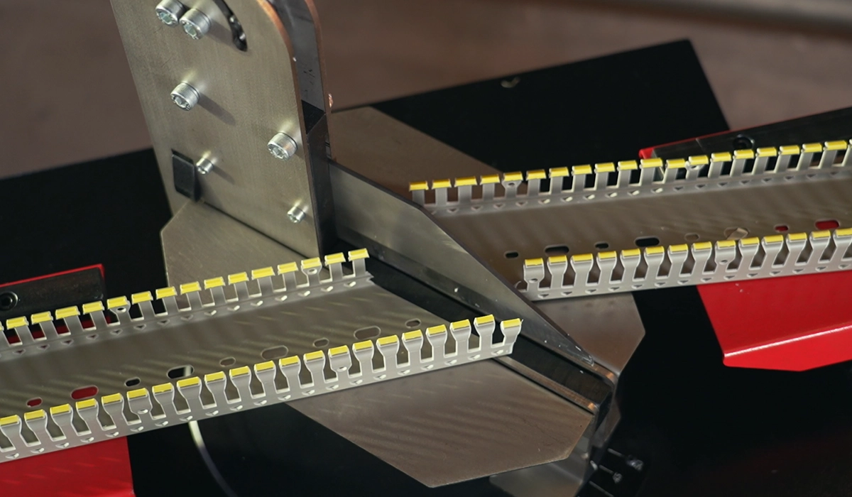
Before starting, it may help to review this benefits of this tool for additional context.
Wiring Duct Size Reference Chart by Wire Count and Gauge
The table below gives starting estimates for common gauges and quantities. Use it as a wiring duct size chart by wire count and gauge, not as a final engineering approval.
Actual cable duct sizing for control panels should always use the manufacturer’s outer diameter. Flexible cable, shielded cable, and high-temperature insulation often increase the diameter.
For example, what size wiring duct do I need for 50 wires depends on the wire gauge and insulation thickness. Fifty 0.5 mm² control wires may fit differently than fifty 1.5 mm² conductors.
Therefore, use these wiring duct sizes for early layout planning, then verify the final duct cross-section during detailed design.
| Wire Gauge | Approx. Outer Diameter | 25 mm Duct | 40 mm Duct | 60 mm Duct | 80 mm Duct |
|---|---|---|---|---|---|
| 0.5 mm² | ~2.0 mm | Up to 10 wires | Up to 25 wires | Up to 55 wires | Up to 100 wires |
| 1.0 mm² | ~2.5 mm | Up to 7 wires | Up to 18 wires | Up to 40 wires | Up to 72 wires |
| 1.5 mm² | ~2.8 mm | Up to 6 wires | Up to 15 wires | Up to 33 wires | Up to 60 wires |
| 2.5 mm² | ~3.5 mm | Up to 4 wires | Up to 10 wires | Up to 22 wires | Up to 39 wires |
| 4.0 mm² | ~4.5 mm | Up to 2 wires | Up to 6 wires | Up to 13 wires | Up to 24 wires |
| 6.0 mm² | ~5.5 mm | Not suitable | Up to 4 wires | Up to 9 wires | Up to 16 wires |
Note: Values assume standard round PVC-insulated wire and 50% fill ratio. Actual capacity varies by wire manufacturer and insulation type. Always verify with manufacturer outer diameter specifications.
You can access the full PDF version of this reference through this link.
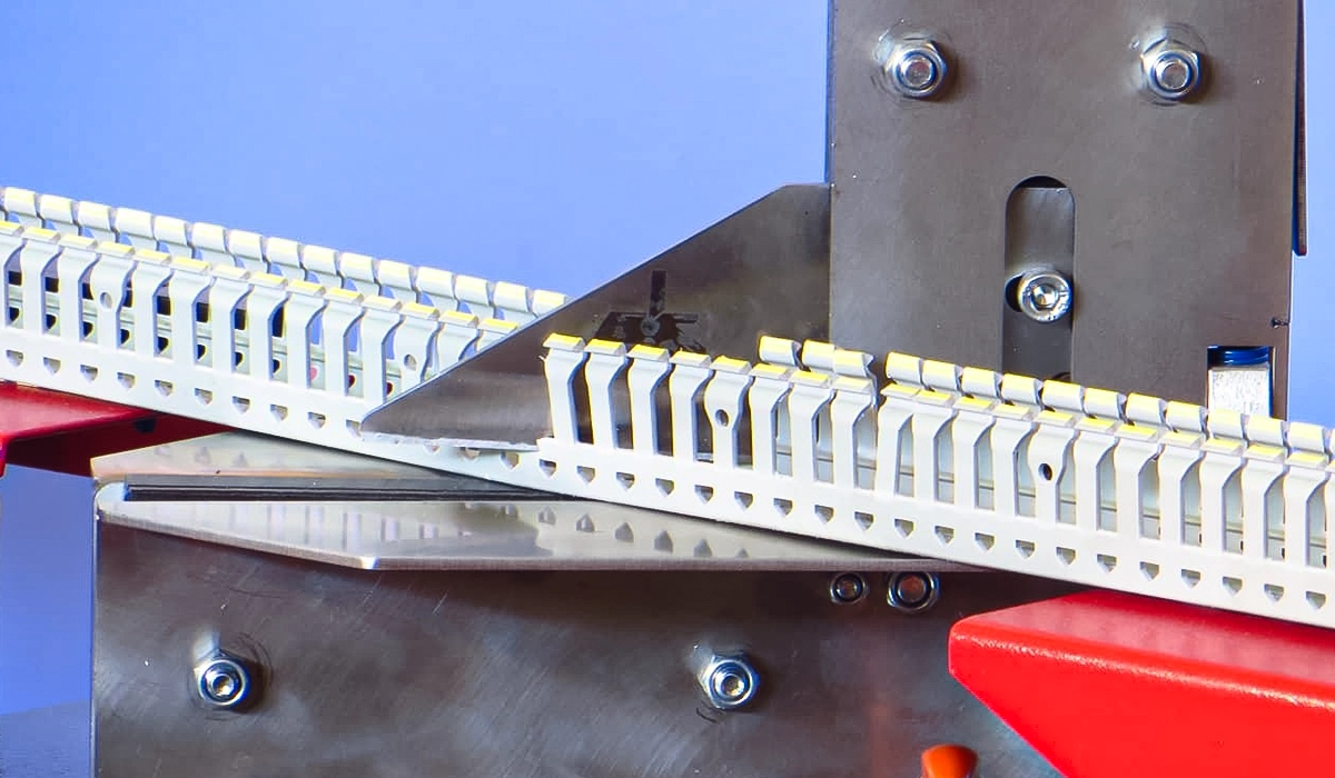
Having the right trimming tool on hand makes adjusting duct lengths much easier.
Width vs. Depth — Which Dimension to Prioritize?
Width and depth solve different design problems. Width helps when wire count rises. Depth helps when large cables stack or when the duct must hold thicker bundles.
However, panel layout can limit both choices. A narrow enclosure may not allow wide duct beside every DIN rail. A shallow enclosure may not allow deep duct near the door.
As a rule, prioritize width when the duct carries many small control wires. Prioritize depth when mixed-gauge cable bundles need more vertical space.
Still, do not treat duct capacity as an isolated calculation. DIN rail panel layout planning, enclosure depth, heat flow, and maintenance access must work together.
The full reference document is available for download to support your research.
When Width Is the Primary Concern
Width matters most when wire count drives the design. More wires entering and leaving a segment need more horizontal space. Therefore, wiring duct width selection should begin with the highest-density route, not the average route. In narrow panels, designers may use a deeper duct to compensate. However, that trade-off only works if door clearance and terminal access remain acceptable.
When Depth Matters More
Depth matters more when the panel includes thick cable bundles, 4 mm² or larger power wiring, cable ties, connectors, or splice points inside the duct body. A practical wiring duct depth guide should also check component height. Deep duct can improve duct capacity, but it may block access in a compact enclosure. Therefore, compare shallow vs. deep duct against real door and device clearances.
The Relationship Between Width and Panel Layout
Wider duct consumes more mounting plate area. As a result, it can reduce the usable space for DIN rail devices, terminals, power supplies, and relays. In panels around 400 mm wide or less, 25–40 mm duct often becomes the practical limit. Larger panels can accept 60–80 mm duct, but designers still need clear service paths.
Special Sizing Considerations for Specific Panel Types
Different panels create different wiring density patterns. A PLC panel often has many small signal wires. A VFD panel has fewer but larger and noisier cables.
Therefore, one electrical duct size chart cannot solve every layout. Each duct run needs its own calculation and routing purpose.
Control wiring, power wiring, shielded cable, and field cable entry zones should not compete for the same duct space. Separation improves serviceability and reduces noise risk.
In practice, the best panel wiring density comes from zoning: signal duct, power duct, field terminal duct, and service loops planned separately.
PLC Panels
PLC panels combine high-count I/O wiring with lower-count power supply wiring. For how to choose wiring duct dimensions for PLC panel, use 40–60 mm narrow slot duct for signal runs and 60–80 mm duct for power runs. Keep analog, digital, and power wiring organized by route. This layout improves troubleshooting and reduces rework during I/O expansion.
VFD Panels
VFD panels need extra attention because motor leads, shielded control cables, and power cables create electromagnetic interference risks. Use separate duct paths for power and control wiring. Wide slot duct at 60–80 mm width and 80–100 mm depth often fits these cable groups better. Also, shielded cable outer diameter can exceed standard wire diameter, so include it in fill calculations.
Main Distribution Panels
Main distribution panels often carry multiple large-gauge feeders, auxiliary control wires, and metering circuits. Use 80–100 mm duct widths with matching depth where cable volume requires it. At this scale, wide slot duct usually improves installation speed and airflow. However, designers should separate feeder paths from control circuits and verify the layout against the assembly design rules.
| Panel Type | Recommended Duct Width | Recommended Duct Depth | Duct Type |
|---|---|---|---|
| PLC / Relay Panel | 40–60 mm | 60 mm | Narrow Slot |
| Motor Control Panel | 60–80 mm | 60–80 mm | Narrow or Wide Slot |
| VFD Panel | 60–80 mm | 80–100 mm | Wide Slot |
| Main Distribution Panel | 80–100 mm | 80–100 mm | Wide Slot |
| Small Machine Panel | 25–40 mm | 40–60 mm | Narrow Slot |
To better understand available options of this tool, this guide breaks down the differences clearly.
Common Sizing Mistakes to Avoid
The first mistake is sizing from the current wire count only. A panel filled to 90% capacity during the initial build leaves no realistic room for modifications. Instead, design for future margin.
The second mistake is using conductor cross-section instead of outer diameter. A 1.5 mm² conductor can have a different total diameter depending on insulation, flexibility, shielding, and manufacturer data.
The third mistake is using one duct size everywhere. Power wiring sections and control wiring sections have different density, heat, and routing profiles. Size each duct independently.
The fourth mistake is choosing depth by habit. Deep duct is not automatically better. In a shallow enclosure, excessive depth can interfere with door-mounted components, ventilation paths, and field cable entry.
Conclusion about wiring duct sizes
Selecting wiring duct sizes should start with wire count, outer diameter, and usable duct area. Width usually drives capacity, while depth affects cable stacking and clearance.
However, a good design also considers heat, future changes, service access, and separation between power and control wiring. This is why panel duct sizing should happen during layout planning, not after component placement.
For most control panels, a 40 × 60 mm or 60 × 60 mm duct gives a strong starting point. Still, high-density PLC panels, VFD panels, and distribution panels need their own duct fill calculation.
Use the 50% fill rule as a practical maximum, then consider 40% initial fill when the panel may expand. That approach gives technicians enough room to install, trace, label, and modify wiring without damaging insulation or turning the duct into a heat trap.



Rate this article
Choose a rating from 1 to 5 stars.
No ratings yet