










For your convenience, if you prefer listening, you can listen to the rest of this article via the audio file below.
Why Wiring Duct Type Matters in Control Panel Design
The choice of wiring duct type shapes nearly every aspect of control panel performance. Indeed, the wrong duct type creates operational problems that compound over the lifetime of the equipment. Wire damage from slot edges, heat buildup from poor airflow, and cumbersome maintenance access all trace back to a poor duct selection. Furthermore, failed UL 508A and IEC 61439 compliance inspections frequently result from overlooked wire management decisions made during the layout phase.
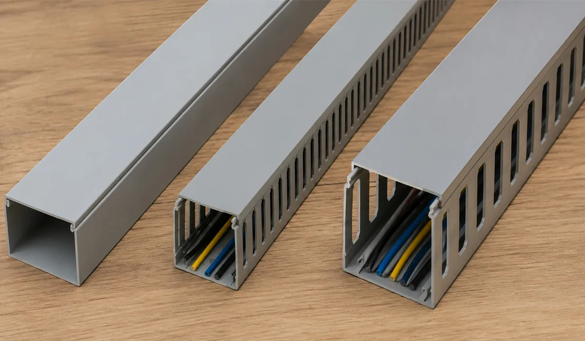
The three main wiring duct types — solid wall, narrow slot, and wide slot — each address a different engineering challenge. Solid wall duct prioritizes maximum wire protection in harsh environments. Narrow slot duct delivers the best balance of accessibility and physical protection for standard panel wiring. Wide slot duct, conversely, handles high-density power wiring and large-gauge cables where routing flexibility and thermal airflow matter most.
Your selection depends on four key factors: the operating environment of the panel, the wire gauges you are routing, the frequency of wire exits along the duct run, and the panel’s overall thermal load. Consequently, a solid understanding of each cable duct type is essential before you finalize your panel layout. The sections that follow cover each type in full technical detail.
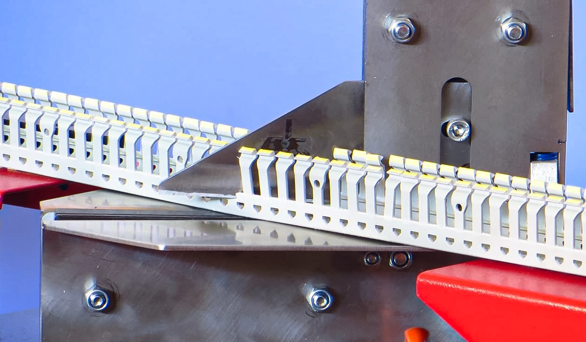
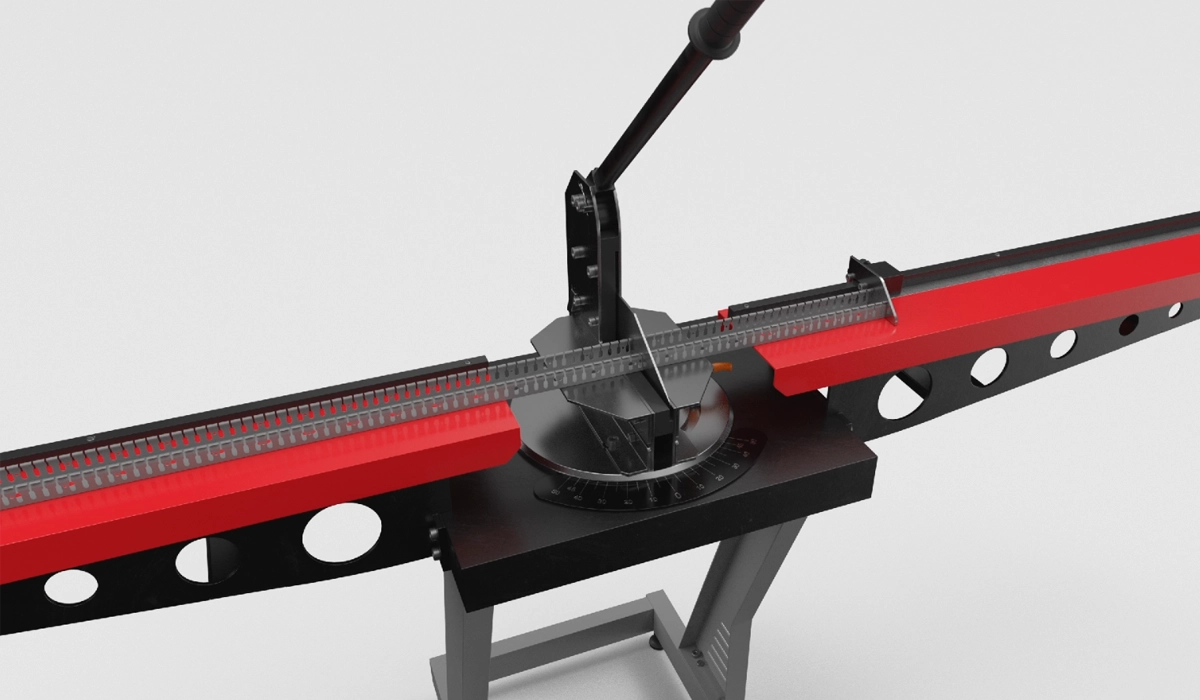
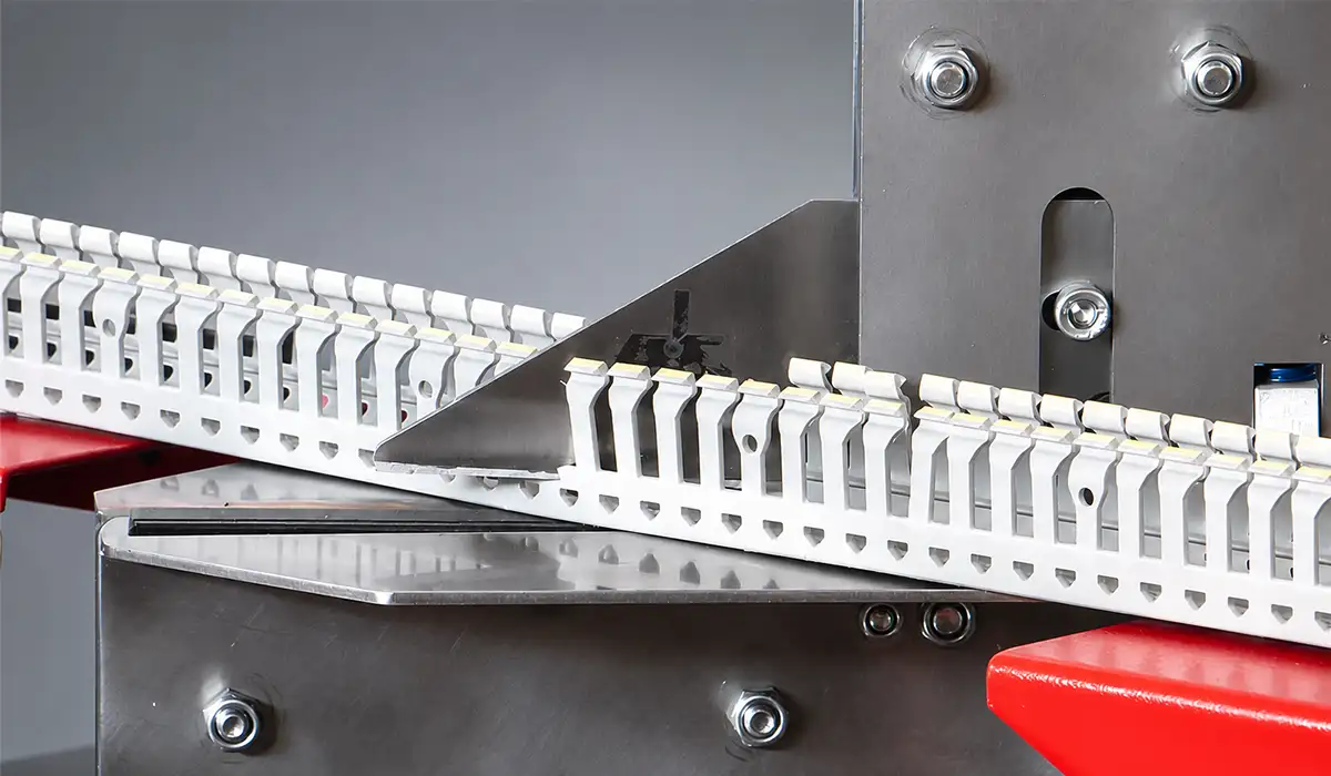
Before anything else, it is worth mentioning that if you are searching for a professional Wiring Duct Cutter for your workshop, capable of cutting various types of ducts, this product is definitely worth checking out.
Solid Wall Wiring Duct — Full Protection for Demanding Environments
Solid wall wiring duct uses and advantages are most relevant in environments where contamination poses a direct risk to wire integrity. This duct type fully encloses the wire bundle with no side openings, making it the strongest physical barrier of the three categories. Its design suits industries where airborne particles, moisture, and mechanical disturbance are daily concer ns — including food processing, woodworking, and metalworking. The trade-off, however, is reduced installation flexibility and limited heat dissipation, which restricts its use in thermally demanding enclosures. Understanding these trade-offs clearly is essential to deploying solid wall duct where it genuinely adds value rather than simply adding cost.
To gather more information and gain a better understanding of all things about Control Panel Cutting Tool, it is recommended that you do not miss reading this article.
What Is Solid Wall Wiring Duct?
Solid wall wiring duct features no slots or perforations along its side walls. Wires enter and exit only through the open top or through cut-outs made during installation. This fully enclosed design, therefore, provides maximum physical protection for the wire bundle. It is the preferred choice for electrical enclosure wire duct applications where particulate contamination presents a real hazard.
Visit this page to learn more about the specifications, applications, and related details about Product specifications and application guidance covering solid wall wiring duct uses, installation methods, and environmental suitability.
Key Advantages of Solid Wall Duct
Solid wall duct delivers several distinct advantages when the operating environment demands them:
- Protects wires from dust, debris, and accidental contact — critical in food processing and woodworking facilities
- Reduces electromagnetic interference (EMI) between parallel wire runs
- Provides a clean, professional appearance inside the panel enclosure
- Meets the physical protection requirements of environments where particulate contamination is a daily concern
If you want to learn more about Meaning duct and collect valuable information, we highly recommend reading this article.
Limitations and Trade-offs
Covers are always required with solid wall duct. Moreover, wire exit points must be planned before installation — adding wires afterward is more disruptive than with any slotted alternative. Heat dissipation through the bundle is poor, so solid wall duct is not suitable for thermally demanding enclosures with high wire density.
| Feature | Solid Wall Duct |
|---|---|
| Side slots | None |
| Wire exit flexibility | Low — exits at top or pre-cut points only |
| Dust/debris protection | Excellent |
| Heat dissipation | Limited |
| Best environment | Dirty, dusty, or contaminated areas |
| Typical application | Food processing panels, woodworking enclosures |
Narrow Slot Wiring Duct — The Industry Standard for General Panel Wiring
Narrow slot wiring duct represents the default choice for the vast majority of industrial control panel builds. Its slotted side walls give installers the routing flexibility they need without sacrificing the level of wire protection required for standard indoor environments. For panel builders seeking a reliable, cost-effective cable management in electrical panels solution, narrow slot duct consistently delivers. It suits PLC enclosures, relay cabinets, motor control centers (MCCs), and machine control panels across a wide range of industries. This section covers what distinguishes narrow slot duct from its alternatives, where it excels, and where its limitations begin.
What Is Narrow Slot Wiring Duct?
Narrow slot wiring duct features evenly spaced, narrow rectangular slots along both side walls. These slots allow wires to exit at any point along the duct run. As a result, installers can branch conductors to terminals, relays, and DIN rail components without pre-planning every exit location. Slot width typically ranges from 3 mm to 6 mm — wide enough for individual conductors but narrow enough to keep loose wire bundles contained. This wire management channel type is the most widely stocked and the most broadly specified in the industry.
Key Advantages of Narrow Slot Duct
Narrow slot duct strikes the best balance between wire accessibility, physical protection, and cost. It is, therefore, the default choice for most standard industrial control panels, PLC enclosures, and machine control cabinets. The slots allow modest airflow through the wire bundle, supporting basic thermal management. Furthermore, adding or modifying wires during panel revisions is straightforward — installers simply route conductors through the nearest available slot without disrupting the surrounding layout. For builders who need reliable panel wiring best practices at a competitive price point, narrow slot duct consistently delivers the right combination of performance and economy.
When Narrow Slot Is the Right Choice
A narrow slot vs wide slot cable duct comparison consistently shows narrow slot as the correct answer for these standard scenarios:
- Control panels with mixed wire gauges ranging from 0.5 mm² to 4 mm²
- PLC and relay wiring where individual wire exits to terminals are frequent
- Panels requiring a practical balance of protection and installation accessibility
- Budget-conscious builds where moderate performance requirements apply
| Feature | Narrow Slot Duct |
|---|---|
| Slot width | Typically 3 mm – 6 mm |
| Wire exit flexibility | High — exit at any slot position |
| Dust/debris protection | Moderate |
| Heat dissipation | Good |
| Best environment | Standard indoor industrial panels |
| Typical application | PLC panels, relay panels, MCC cabinets |
You can find more background information and related technical notes about Application guidance for selecting slotted versus closed cable duct in standard panel environments, through this reference link.
Wide Slot Wiring Duct — Built for High-Density and Large-Gauge Wiring
The best wiring duct type for high-density panel wiring is, in most cases, wide slot duct. Its open-slot design accommodates large cable bundles, allows cable ties and connectors to pass freely through the wall openings, and supports excellent airflow through thermally demanding sections of the panel. Wide slot duct — also called finger duct or comb duct — is particularly common in variable frequency drive (VFD) panels, power distribution boards, and large OEM machine enclosures where cable gauge, bundle size, and heat all rise simultaneously. Choosing this duct type correctly requires understanding both its capabilities and its environmental limitations.
What Is Wide Slot Wiring Duct?
Wide slot wiring duct features large, open slots along its side walls with slot widths typically starting at 10 mm and reaching up to 25 mm. The wall sections between slots are narrow, giving the product its distinctive finger- or comb-like profile. This open slot duct design targets applications where large numbers of wires need to exit the duct, or where cable diameter makes narrow slots impractical. It is a purpose-built solution for power wiring sections of industrial panels.
Key Advantages of Wide Slot Duct
Wide slot duct delivers measurable advantages in demanding power wiring scenarios:
- Accommodates large-gauge wires (6 mm² and above) without bending stress or conductor damage
- Allows cable ties and larger connectors to pass freely through the wall openings
- Reduces installation time significantly in high-density wiring sections
- Provides excellent airflow through the cable bundle — a critical factor in thermally demanding VFD and power panels
- Simplifies wire pulling and bundle routing during panel assembly
When Wide Slot Is the Right Choice
Wide slot duct outperforms narrow slot in specific, well-defined scenarios: power distribution panels with thick cable harnesses, VFD panels with large motor leads, and applications where assembly speed is a priority. However, the open design offers minimal protection from airborne debris. Therefore, wide slot wiring duct is not appropriate for dirty or contaminated environments without additional physical guarding.
| Feature | Wide Slot Duct |
|---|---|
| Slot width | Typically 10 mm – 25 mm |
| Wire exit flexibility | Very high — large bundles exit freely |
| Dust/debris protection | Low |
| Heat dissipation | Excellent |
| Best environment | Clean indoor environments, VFD panels |
| Typical application | Power distribution, VFD panels, large OEM machines |
Side-by-Side Comparison — Solid Wall vs. Narrow Slot vs. Wide Slot
This wiring duct comparison consolidates every key performance attribute across all three types in a single table. Reviewing it makes the decision logic clear for most panel builders: narrow slot is the standard default, wide slot handles power wiring, and solid wall addresses harsh environments.
| Criteria | Solid Wall | Narrow Slot | Wide Slot |
|---|---|---|---|
| Slot size | None | 3 mm – 6 mm | 10 mm – 25 mm |
| Wire exit flexibility | Low | High | Very High |
| Max wire gauge suited | Any (top exit) | Up to ~4 mm² | 6 mm² and above |
| Dust/debris protection | Excellent | Moderate | Low |
| Airflow / heat dissipation | Poor | Good | Excellent |
| Installation speed | Slow | Medium | Fast |
| Suitable environment | Dirty/dusty | Standard indoor | Clean indoor |
| Cover required | Yes — always | Recommended | Recommended |
| Typical cost | Moderate | Low | Low–Moderate |
| Most common application | Food/wood processing | PLC & relay panels | VFD & power panels |
Most panel builders default to narrow slot slotted cable trunking for their control and signal wiring sections. They then upgrade to wide slot duct in areas carrying power cables and motor leads. Finally, they reserve solid wall closed duct for panels installed in environments with significant contamination risks. This layered approach — combining duct types within a single panel — optimizes performance, thermal management, and cost across the full layout without compromise.
How to Choose the Right Wiring Duct Type — A Decision Framework
Learning how to choose the right wiring duct type for your application is straightforward when you work through a structured four-step process. This cable duct selection guide applies equally to new panel builds and to retrofit projects where existing duct types are under review.
- Assess your environment. Is the panel operating in a clean room, a standard factory floor, or a dirty process area such as a woodworking shop or food processing line? Contaminated environments push your selection firmly toward solid wall duct to maintain wire integrity over time.
- Identify your wire gauges. If your panel includes cables above 4 mm², wide slot duct is almost certainly necessary in those sections. Standard mixed gauges from 0.5 mm² to 4 mm² route comfortably through narrow slot duct without bending stress or slot friction.
- Estimate wire density and exit frequency. High exit frequency — many branches to terminals, relays, and other components — favors slotted duct. Tightly bundled runs with few exits can tolerate solid wall duct, provided the environment justifies it.
- Consider thermal load. High-heat panels benefit directly from wide slot duct’s superior airflow through the cable bundle. Conversely, solid wall duct should be avoided in thermally demanding enclosures where heat buildup poses a risk to wire insulation ratings.
Following these four steps gives you a defensible, technically grounded duct type specification — one that supports both panel performance and compliance with UL 508A and IEC 61439 requirements.
For offline reading about Governs wire management requirements, fill ratios, and voltage class separation for industrial control panels in North America, you can download the complete document from this link.
Installation Tips That Apply to All Wiring Duct Types
Good installation practice strengthens your panel’s performance regardless of which duct type you select. First, always calculate the fill ratio before finalizing duct size. Target a maximum fill of 50–60% of the duct’s cross-sectional area to allow for future wiring additions and adequate airflow through the bundle. Exceeding this ratio makes maintenance difficult and accelerates insulation wear over time.
Second, never route line voltage and signal or control wiring in the same duct run. Mixing these wire classes creates interference risk and may violate the voltage class separation requirements of IEC 61439 and UL 508A. Instead, plan separate electrical panel layout duct runs for power and control wiring from the earliest design phase — retrofitting separation later is significantly more costly.
Third, cut duct cleanly using a fine-tooth hacksaw or a dedicated duct cutter. Rough or jagged cut edges damage wire insulation during installation and cause ongoing abrasion as cables shift under vibration. Fourth, label all duct sections during the planning phase rather than after installation, when physical access to the backs of duct runs becomes difficult. Finally, always leave service loops at wire termination points. These short loops of extra conductor give future maintenance technicians the slack they need to re-terminate without pulling entirely new cables — a small investment in planning that saves substantial maintenance time.
For engineers and procurement teams, this downloadable file provides a useful reference for decision-making.
Conclusion about Wiring Duct
Choosing the right wiring duct type is not just a layout decision. It directly affects wire protection, thermal behavior, installation speed, maintenance access, and long-term panel reliability. Solid wall duct is the best option when the enclosure must protect wiring from dust, debris, and harsh operating conditions. Narrow slot duct remains the practical default for most PLC panels, relay cabinets, and standard industrial control panels because it balances protection, accessibility, and cost. Wide slot duct is the preferred choice for high-density wiring, large-gauge cables, VFD panels, and power distribution sections where airflow and routing flexibility are critical.
In many professional panel builds, the best solution is not one duct type but a combination of types. A well-designed enclosure may use narrow slot duct for control wiring, wide slot duct for power cable sections, and solid wall duct in areas exposed to contamination risk. This approach supports cleaner wiring, easier troubleshooting, better thermal management, and stronger alignment with UL 508A and IEC 61439 design expectations.
Before finalizing your electrical panel layout, always evaluate the environment, wire gauge, wire density, exit frequency, and thermal load. Then size the duct correctly, keep power and signal wiring separated, and cut every duct section cleanly to protect wire insulation. Careful duct selection and precise installation may seem like small details, but they are exactly the details that separate a reliable industrial control panel from one that creates problems during inspection, commissioning, or maintenance.



Rate this article
Choose a rating from 1 to 5 stars.
No ratings yet