

In modern industrial and commercial facilities, electricity is a critical resource. Its efficiency directly impacts operational costs and equipment performance. However, one often overlooked yet crucial parameter in electrical systems is the power factor. Poor power factor management silently drains budgets through inflated energy bills, penalty charges, and accelerated equipment wear. Many facility managers and engineers, despite its importance, may lack the tools to assess their power factor or are unsure how to take corrective action.
This article provides a practical, step-by-step guide to calculating the required capacitor bank capacity using data readily available on your electricity bill. Whether you manage a manufacturing plant, a commercial building, or any energy-intensive operation, understanding and correcting your power factor is one of the most cost-effective improvements you can make.
Prefer listening? You can play the audio version of the rest of this article below.
What is Power Factor and Why Is It Important?
Power factor (Cos φ) is a ratio that shows how much of the electrical energy drawn from the grid is actually converted into useful work — such as lighting, heating, or mechanical motion. A power factor of 1.0 (unity) means all consumed energy is doing productive work. Anything below that means a portion circulates reactively without contributing to output.
For a comprehensive understanding of Standards on Switchgear and Busbars, we highly recommend reviewing this article.
Active Power (P): Real energy that performs useful work, measured in kilowatts (kW).
Reactive Power (Q): Energy that oscillates between the source and inductive loads such as motors and transformers, measured in kVAR. It does no useful work but stresses the network.
Apparent Power (S): The vector combination of active and reactive power, measured in kVA.
| Description | Symbol |
|---|---|
| Active Power — Real energy that performs useful work. | P (kW) |
| Reactive Power — Oscillates between source and inductive loads. Does no useful work. | Q (kVAR) |
| Apparent Power — Vector combination of active and reactive power. | S (kVA) |
Power Factor Definition
A low power factor forces utilities to deliver more current for the same useful output. This is why most providers impose penalties on industrial consumers whose power factor falls below a defined threshold — typically 0.90 or 0.95.
Reading and Understanding an Industrial Electricity Bill
Your industrial electricity bill contains two key figures needed for power factor analysis:
kWh (kilowatt-hours) represents the active energy consumed — the work actually done.
kVArh (kilovolt-ampere reactive hours) represents the reactive energy drawn by inductive equipment such as motors and transformers, which does no useful work but strains the network.
Some bills display the power factor directly. Others only provide kWh and kVArh values, from which you must calculate it yourself using the following two steps.
If the information related to Types of Electrical Wires and Cables Industrial Electricity Bill was interesting and informative to you, researching topic Y can be very engaging.
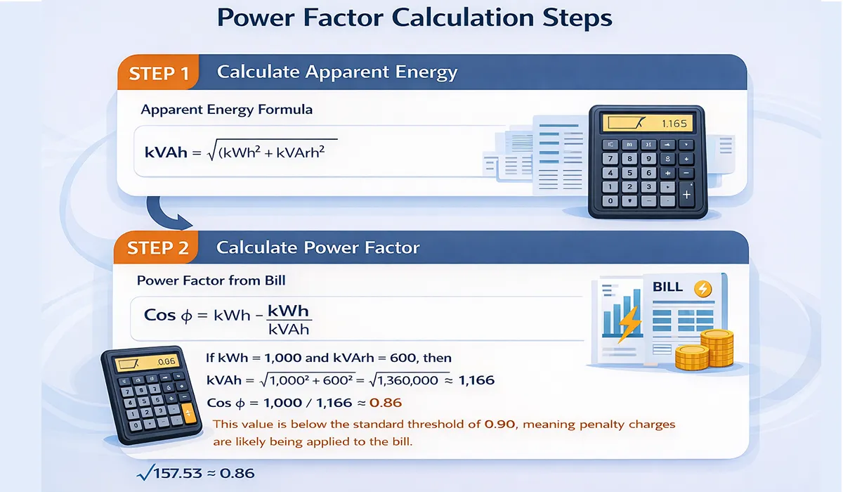
Step 1 — Calculate Apparent Energy
Apparent Energy Formula
Step 2 — Calculate Power Factor
Power Factor from Bill
Example:
If kWh = 1,000 and kVArh = 600, then
kVAh = √(1,000² + 600²) = √1,360,000 ≈ 1,166, and
Cos φ = 1,000 / 1,166 ≈ 0.86.
This value is below the standard threshold of 0.90, meaning penalty charges are likely being applied to the bill.
Calculating the Required Capacitor Bank Capacity
Once the current power factor is known, the required reactive compensation can be determined using the following formula:
Core Capacitor Sizing Formula
| Description | Symbol |
|---|---|
| Required capacitor bank capacity (kVAR) | Qc |
| Active power (kW) — from your bill or metering | P |
| Angle of the current power factor = Cos⁻¹(current PF) | φ₁ |
| Angle of the target power factor = Cos⁻¹(target PF) | φ₂ |
Example:
Suppose P = 500 kW, current power factor = 0.86, and target power factor = 0.95.
Then φ₁ = Cos⁻¹(0.86) ≈ 30.68° giving tan φ₁ ≈ 0.5936, and
φ₂ = Cos⁻¹(0.95) ≈ 18.19° giving tan φ₂ ≈ 0.3287.
Therefore, Qc = 500 × (0.5936 – 0.3287) = 500 × 0.2649 ≈ 132.5 kVAR.
Further exploration of Capacitor can be found in the following recommended reading.
Practical Calculation Tips
Variable Loads: For facilities with fluctuating demand, use average monthly consumption figures or consider a stepped (automatic) capacitor bank that adjusts compensation dynamically.
Voltage Variations: Always account for the actual network voltage in your calculations, as deviations from nominal voltage affect capacitor output.
Safety Margin: Add 10–20% extra capacity above the calculated value to guard against over-compensation and to accommodate load growth.
System Frequency: Standard frequency in most regions is either 50 Hz or 60 Hz. Confirm your local grid frequency and adjust calculations accordingly, as capacitor reactance is frequency-dependent.
Harmonic Distortion: In facilities with significant non-linear loads such as variable frequency drives or UPS systems, consult a power quality specialist before sizing capacitors, as harmonics can cause resonance issues.
Return on Investment and Economic Savings
The financial case for capacitor bank installation is compelling. Consider a facility with a monthly electricity bill of $10,000, of which $2,000 represents penalties due to a low power factor of 0.85. By installing an appropriately sized capacitor bank to correct the power factor to 0.95, penalty charges are eliminated entirely, and overall energy consumption is optimized by 5–10% through reduced line losses, resulting in estimated monthly savings of $2,500 – $3,000.
Payback Period
In practice, payback periods typically range from 6 to 12 months, making capacitor banks one of the highest-return electrical investments available to industrial operators. Beyond direct savings, the long-term benefits include a 5–15% reduction in energy losses in cables and transformers, a 20–30% increase in equipment lifespan due to lower reactive stress, and deferred infrastructure upgrades as improved power factor frees up capacity in transformers and feeders.

Differences in Electricity Billing: USA vs. European Countries
Electricity billing systems vary widely between countries, which can affect how power factor is presented and how easily it can be corrected.
European Countries: In many European countries, industrial electricity bills provide clear breakdowns of active (kWh) and reactive (kVArh) energy usage. Power factor may be displayed directly on the bill, making it easy for businesses to see where they stand and whether they are at risk of penalty charges. In addition, EU regulations typically impose stricter standards for power factor correction, ensuring that businesses are incentivized to maintain a power factor close to unity (1.0).
United States: In contrast, electricity bills in the USA may not always display kVArh values, and businesses often need to request them from their utility provider or calculate them manually. Although penalty charges for poor power factor are common in the US, the way these penalties are assessed can vary more significantly than in European countries. In many cases, utilities in the US offer incentives for businesses to correct their power factor, but these incentives may not be as regulated or standardized as those in the EU.
By understanding how power factor is reflected on your electricity bill — whether directly or indirectly — you can take the necessary steps to improve your energy efficiency, avoid penalties, and optimize your operations.
This article serves as a valuable resource for those seeking detailed information on Electricity sector of the United States.
Conclusion
Calculating and correcting the power factor through a properly sized capacitor bank is one of the most straightforward and financially rewarding steps an industrial or commercial facility can take. By analyzing the kWh and kVArh figures on your electricity bill and applying the formulas outlined in this guide, you can determine exactly how much reactive compensation your system needs — and build a clear business case for the investment.
For complex installations involving variable loads, harmonic distortion, or large-scale distribution systems, it is strongly recommended to engage a qualified power systems engineer to ensure the capacitor bank is designed and integrated safely and effectively.


