What is an insulator?
The main function of an insulator is to isolate the conductor from the panel body. Among the available types of insulators, support insulators can be mentioned. A type of it is used in the building industry and is known as panel neutral insulators. Support insulators are used to insulate busbars from earth in substations and panels. A panel neutral insulator is used to isolate the neutral line from the panel and is classified into three categories: boot-type insulator, two-screw (or cylindrical) neutral insulator, and SM insulator.
Most conductors used in panels are made of copper, but under special conditions where using copper would cause problems (such as environments containing sulfur vapor), aluminum can be used. Conductors are used in two forms: wire and busbar. Wires (mostly stranded wire) are used to establish electrical connections between equipment inside the panel, and also to connect the grid and the consumer to the panel. The current-carrying capacity of a busbar depends on its cross-sectional area. It is common to express the busbar cross-section as its dimensions. Since busbars play a crucial role in the production of electrical panels, obtaining more information about Busbar Fabrication Machines can be very important and essential.
Alternatively, an audio version of this article is available below for your convenience.
Types of insulators
Insulators are categorized into pin insulators, tension insulators, suspension insulators, support insulators, spool insulators, bushing (through) insulators, and stay insulators. Insulators are made of porcelain, glass, and composite materials.
Pin insulator
This type of insulator is installed on a bolt or a steel base. The pin insulator is fixed in its position (for example, on a cross-arm), and the conductor passing over it is fastened to it by wire.
If you are looking for more information about topic pin insulator, it is recommended not to miss reading this article.
Suspension insulator
This type of insulator is used at the beginning and end of angled sections in lines. As its name suggests, the suspension insulator hangs from the cross-arm, and the conductor wire is connected to its end using a clamp.
Tension insulator
The application of this insulator is mostly at the start and end of power lines in places with bends and angles, and in locations such as crossings over rivers and valleys.
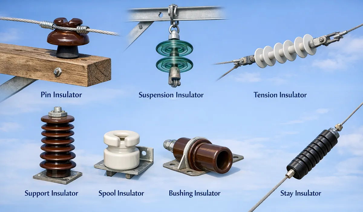
Support insulator
Support insulators are cylindrical with protrusions and indentations and exist in two types: solid and hollow. A solid support insulator has higher mechanical and electrical strength against puncture, and the hollow type is used for cases where higher mechanical load tolerance is required.
If you are looking for more information about Support insulator, it is recommended not to miss reading this article.
Spool insulator
These insulators are made of porcelain and are used in low-voltage networks.
Insulator creepage distance
Leakage current consists of bulk leakage current (capacitive and resistive) and surface leakage current. Surface leakage current passes over the surface of solid insulation between two conductive parts (electrodes) with different potentials.
In the investigation and measurement of creepage distance, accessible surfaces of insulating enclosures of electrical equipment are also considered an electrode. The criterion for accessibility is the possibility of contact with fingers or a test finger. Contaminants that are conductive, or contaminants that are not inherently conductive but become conductive by absorbing water or moisture, settle on the creepage path and as a result surface leakage current flows. The magnitude of surface leakage current depends on voltage and the impedance of the power source, the electrical conductivity of contamination, creepage distance, and the width of the path.
Covering the creepage distance with contamination such as metal dust causes a very large surface leakage current to pass, and as a result the insulation fails.
Contaminants that become conductive by dampness or water absorption also pass surface leakage current. Moisture dries sooner at some point on this path than at other points, and micro electrical arcs are created. If the energy of these micro-arcs is sufficient, it decomposes the solid insulation and leaves a carbon residue, forming a conductive path on the insulation surface.
Factors affecting creepage distance
The effect of contamination depends on the micro-environment in which the creepage distance or air clearance is located. Therefore, even in different parts of the same electrical equipment, creepage distances may be different. Contamination around air clearances and creepage distances is divided into four degrees:
In contamination degrees 2, 3, 4, the possibility of water droplet condensation must be considered. Condensation can occur due to equipment temperature dropping below the ambient dew point, contamination of the insulation surface with hygroscopic dusts, contamination of the insulation surface with salt in a place with high relative humidity, and so on.
The direction and location of the creepage distance and the air clearance can affect contaminant accumulation due to gravity forces, centrifugal forces, natural or forced airflow.
Creepage distances that are adjacent to heating elements or components with heat losses are less vulnerable due to rapid drying of the insulation surface. But if repeated condensation of water droplets is possible in these distances, the risk of forming a conductive path on the insulation surface increases. If the information related to creepage distance and insulation challenges was interesting and informative to you, researching common challenges in busbar fabrication can be very engaging.
Air clearance
By definition, air clearance is the shortest distance between two conductive parts through air. In measuring air clearance, accessible surfaces of the insulating enclosure of electrical equipment are also considered a conductive part. The criterion for accessibility is the possibility of contact with fingers or a standard test finger.
Protecting electrical equipment against transient overvoltages that are transferred to them directly or through the power distribution system, or that are generated within them, is necessary in terms of safety, uninterrupted operation, and so on.
To limit transient overvoltages, devices are used that operate by accumulating or dissipating the energy of the transient voltage impulse. Surge arresters, impulse suppressors, and metal-oxide varistors are examples of such devices.
In installation systems where no action has been taken to limit transient overvoltages, transient overvoltages break down along the path with lower dielectric strength, either through the distance between conductors or through solid insulation. The consequences can be minor or catastrophic. These consequences depend on the impulse energy of the transient overvoltage, the nominal voltage of the installation, and the formation of a fault current.
The formation of fault current is unpredictable, because it depends on the matching of the time phases of the transient voltage and the time phases of the distribution system voltage, ionized gases between electrodes due to the spark caused by the impulse voltage, uniform or non-uniform electric field between electrodes, electrode material, and also the impedance characteristic of the circuit against the voltage impulse.
The maximum peak value of the impulse voltage (with a standard waveform) that the insulation can withstand under standard conditions is called the impulse withstand voltage level.
The nominal insulation voltage and the impulse withstand voltage level are called the insulation level. The insulation level is necessary for electrical equipment in terms of coordination of insulation components. For a comprehensive understanding of precision in electrical panel manufacturing, we highly recommend reviewing this article on why precision matters in busbar fabrication.
Air clearance as a method of limiting transient overvoltage
In places where the impulse energy of a transient overvoltage is limited and the impulse withstand voltage level is greater than 1000 volts, air clearance can be used in electrical equipment as a simple means to limit transient overvoltages, without causing interruption in operation and without causing damage to equipment and surroundings. In this case, this must be clearly and explicitly stated so that negligence in design, or changes to air clearances due to tampering during assembly, repair, and so on, does not eliminate insulation coordination.
Each air clearance has its own impulse withstand voltage level, which depends on major factors such as the shape of conductors or electrodes between which the clearance is located, air pressure, and contamination.
If the electrode dimensions are much larger than the distance between them, the field in the air clearance is uniform; otherwise, the field is non-uniform. In a non-uniform field, dielectric stresses are not distributed evenly and uniformly, meaning dielectric stress at one or more points is higher than at other points. Therefore, a larger air clearance is selected to prevent dielectric breakdown.
Further exploration of Air clearance can be found in the following recommended reading.
Effect of altitude
Altitude is also a major factor. At constant temperature and pressure above the critical pressure, in a uniform field the breakdown voltage is proportional to the product of air pressure and the distance between electrodes. This relationship is approximately valid for non-uniform fields as well. Another effective factor on the impulse withstand voltage level of air clearance is contamination.
Effect of contamination
Contamination means an increase in foreign materials including solids, liquids, and gases that can lead to a reduction in the dielectric strength of air, a reduction in air and creepage distances, and the surface resistance of solid insulation. Contamination grades the micro-environments in which air clearances and creepage distances are located into degrees 1, 2, 3, 6.
The electrical conductivity of contaminating materials is mainly due to the presence of water, soot, metal dust, carbon, and similar components. Conductive contamination due to ionized gases and metal deposition, which mostly occurs in switching devices, is not our topic. If ionized gases are present, air clearance cannot be used to limit transient overvoltages; instead, a suitable method must be used to extinguish the arc.
To prevent contamination, depending on the case, an enclosure or sealing that is impermeable to the relevant contaminant can be used. But if water droplets condense in the equipment or contaminants are produced, these measures are not effective either. In any case, the principle is that the air clearances intended for limiting transient overvoltages must remain established and effective throughout the useful life of electrical equipment. If the details you gathered about contamination and its effects on electrical equipment were interesting and insightful, you may find diving deeper into busbar processing machine in transformers equally captivating.
Relationship between insulator creepage distance and air clearance
A creepage distance cannot be shorter than the air clearance. That is, the shortest creepage distance is taken equal to the air clearance. For example, in the case of mineral insulating materials that do not tend to form a conductive path on the surface, the air clearance can be taken equal to the creepage distance. Apart from this limitation, there is no other physical relationship between air clearance and creepage distance.
At operating voltages below 32 volts, a conductive path on the insulation surface or insulation erosion does not occur, and determining the minimum creepage distance is only for electrolytic corrosion. If you are looking for more information about busbar arrangement in panels, it is recommended not to miss reading this comprehensive guide to busbar arrangements.
What is a busbar?
A busbar is a copper or aluminum piece in a rectangular prism shape that, instead of cable, has the task of supplying power to equipment inside the electrical panel. The current capacity of panel busbars must be higher than the rated current of the equipment feeder breaker.
All generators, transformers, wires, and cables of a power plant that have equal voltage are connected by a bar or a conductor called a busbar (Busbar) in each phase. In the busbar, all the energy of generators, transformers, or both is combined, and from there it is guided directly at the same voltage, or with the help of a step-up or step-down transformer at another voltage, to consumers or to other busbars. Therefore, it can be said that the busbar is a means of collecting and distributing energy at the same time.
In the figure below, you see the placement of the busbar in the power transmission and distribution system in a simple case with a single busbar.
Busbars are used as the main conductor in the panel for collecting and distributing electrical energy. Busbar arrangement in panels is done using the simple busbar method and all panel equipment is connected to these busbars. In panels that have separate cell compartmentalization, busbar arrangement must be such that if work is performed inside any one of the cells, continuity of operation in other parts is not interrupted. For a comprehensive understanding of the full journey from raw material to finished conductor, we highly recommend reviewing this article on the journey of busbar fabrication from copper to current.

Types of busbars
In the rest of this article, I will briefly introduce the types of busbars.
Phase busbar
Normally, the electrical capacity of the phase busbar should not be less than 150% of the rated current of the main feeder breaker of the panel.
Earth and neutral busbar
The earth and neutral busbar is a terminal that is provided and installed for connecting protective conductors, including bonding conductors for equipotentialization and operational earth conductors (if present).
The cross-sectional area of the neutral and earthing busbar must not be less than half of the cross-sectional area of the phase busbar. Note that if the material of the phase or neutral busbar changes from copper to an element such as aluminum with lower conductivity, a larger cross-sectional area must be selected for it.
Neutral and phase busbars must be insulated from the panel body by an insulator, but the earth busbar must be connected directly to the panel body. Note that whatever the rated current of the equipment feeder breaker is, the panel busbars and none of the live parts of breakers, including their terminals, must be accessible or touchable. Panel-type breakers whose terminals are accessible must have a complete protective cover.
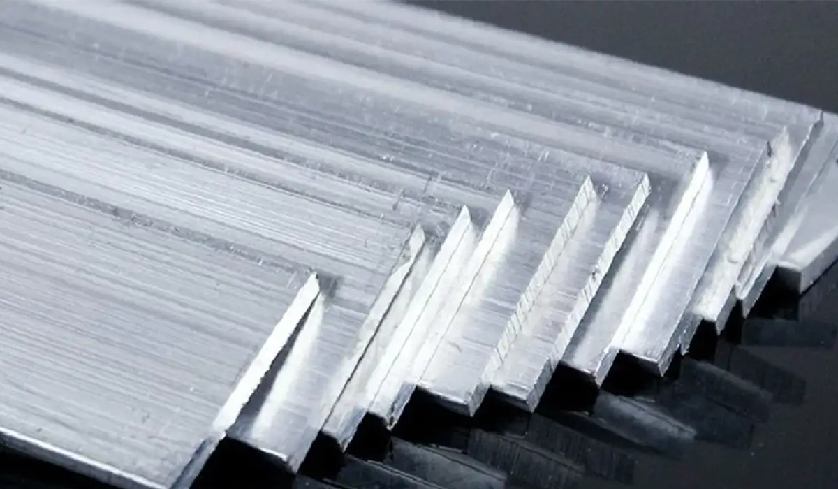
Comparison of copper and aluminum busbars
In selecting a busbar, the following points must be considered:
- The static strength of aluminum (due to larger cross-sectional area for equal current) is greater than copper.
- The dynamic withstand of aluminum (due to larger cross-sectional area for equal current) is equal to copper.
- Temperature rise due to passing currents, because of lower specific current and better heat exchange in aluminum, is less.
- Aluminum does not produce a large amount of ash due to sparking and burning. This ash is not conductive and does not damage insulators. Copper is very sensitive to sulfur vapor and produces copper oxide, which has low conductivity.
Copper is very sensitive to sulfur vapor and produces copper oxide, which has low conductivity. Aluminum is stable against hydrochloric acid, sulfuric acid, and ammonia, but is sensitive to mercury chloride vapor. Aluminum has surface oxidation that creates a thin insulating layer on the metal, which under pressure becomes indented, and its corrosion due to electrolyte is severe.
Aluminum is stable against hydrochloric acid, sulfuric acid, and ammonia, but is sensitive to mercury chlorine vapor. Aluminum has surface oxidation that creates a thin insulating layer on the metal. Under pressure it becomes indented, and its corrosion due to electrolyte is severe. Today, in new panels and modern cable routing, busbar is usually used instead of busbar and cabling. If the information about copper and aluminum busbar properties was valuable and interesting to you, researching busbar systems and the benefits of copper vs aluminum could be just as captivating.
Table of specifications of copper and aluminum conductors
| Aluminum | Copper | Item |
|---|---|---|
| 2.7 | 9.8 | Density kg/dm3 |
| 35 | 56 | Conductivity |
| 658 | 1085 | Melting temperature |
| 15 mm | 10 mm | Elongation in 10 m at 60°C |
Load capacity of copper busbars
The continuous current capacity that copper and aluminum conductors can carry has been obtained based on the following assumptions:
a) Ambient air is still and without movement.
b) Oxidized parts of bare conductors have an emissivity coefficient of 4% for copper and 35% for aluminum.
c) Painted conductors have an approximate emissivity coefficient of 9%.
In high-power panels, it may be necessary to use more than one busbar for each phase to provide the passing current. In this case, it is necessary that the busbars of each phase be placed next to each other with a spacing equal to the height of that same busbar.
Table of constant load capacity of flat copper busbars at 30°C in amperes
Notes that must be considered for using the tables of constant load capacity of flat copper and aluminum busbars at 30°C in amperes:
- The specified load capacity in each table is valid for busbars in which the larger side of the cross-section (a) is in the vertical position.
- In each phase, the distance between two adjacent busbars (b) is equal to the thickness of the intended busbar.
Relationships for busbar load capacity in the panel
The load capacity values (I) at temperatures above 30°C (ϴ) can be calculated from the following relationship:
The permissible current (I) for other frequencies (f) is calculated using the following relationship:
In each phase, only the external surfaces of the busbars must be painted. The following conditions are valid for alternating current (ac).
a. The average temperature rise in the table is equal to 30°C provided that the distance between the busbar sets of two phases (d) is not less than ten times the diameter of the sum of the busbars of one phase (c). If the distance (d) is less than ten times the distance (c), the load capacity values in the tables are reduced according to the following coefficients:
b. Busbars that face adjacent phases will have a few degrees higher temperature.
| Reduction Factor | Ratio c:d |
|---|---|
| 0.97 | 8 |
| 0.94 | 6 |
| 0.9 | 4 |
| 0.8 | 2 |
Busbars used in the electrical panel
The busbars used in the panel are often made of copper or aluminum, which have good electrical conductivity and mechanical properties. For copper busbars, the VDE0201 standard is used, and for aluminum busbars, the VDE0202 standard is used.
- The maximum diameter of holes made on the busbar must not be more than one third of its width. For example, in a busbar with a width of 30 mm, the maximum hole diameter is 10 mm.
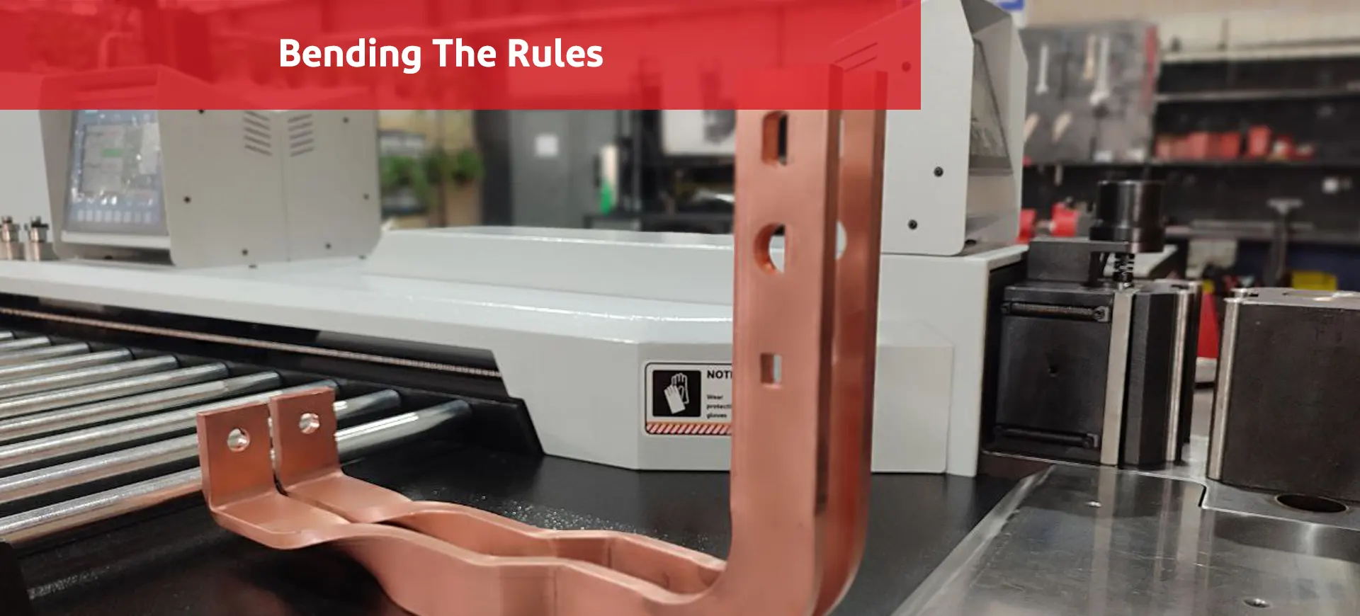
- Busbar bending, considering its width, must be done in such a way that it does not exceed the maximum permissible bending stress of the busbar.
- The connection of the busbar to the breaker must be in line with the breaker contacts to prevent the creation of electrodynamic force. This force can cause vibration or even opening of the contact.
- Any cutting and filing of the busbar that causes a reduction in dimensions at the connection point to breakers must be avoided.
Key points in busbar installation
Maximum continuous temperature of the busbar
For busbars whose connections are bolted and are not oxidized or not lubricated, it is about 120°C, and if silver-plated, this temperature can be considered up to 160°C. With increasing temperature, the strength of conductor materials decreases, and this effect is faster for aluminum than copper. In short-circuit conditions, the temperature of the aluminum conductor must not exceed 180°C and the temperature of the copper conductor must not exceed 200°C.
Selecting the cross-sectional shape of the busbar
The cross-sectional shape of the conductor not only affects the torsional strength of the busbar, but also affects the load capacity of the busbar. When using busbar in direct current, due to the absence of skin effect, the important factor in selecting the cross-sectional shape of the busbar is only the thermal capacity of the busbar at that current. In alternating current, the skin effect is considered an important factor in increasing conductor resistance. This effect can be reduced by selecting an appropriate cross-section. At low currents, a single or double flat busbar is preferred. In this case, using a double busbar reduces losses. At higher currents, round (tubular) and channel busbars can be used.
Calculating the busbar conductor cross-section
The cross-section of conductors inside the panel is obtained based on the maximum required current and using the permissible current table of wires. The calculated cross-section is used, to establish electrical connection between the panel and other related equipment, for determining the required gland, terminal size, lug, and ferrule. For example, in a 16X4 mm² cable, a gland for a cable diameter of 23.5 mm and a terminal number 16 are required. Connecting conductors to terminals and other equipment is possible using screws, clamps, and similar devices.
Busbar cross-section is expressed as its dimensions. For connecting two busbars together or taking a branch from the main busbar, it is better that the connection is direct and without an intermediate connector. For branching, first remove any contamination and grease from the branch point, clean it with fine sandpaper, and apply a thin layer of special oil, then fasten the two pieces together. Note that the connection of two busbars depends on the pressure of those two surfaces on each other.
Phase, neutral, and grounded busbars are run along the entire length of the panel and are fixed at appropriate locations using support insulators. It is better to fasten the earth busbar to the body without using an insulator, and if a common busbar is used for neutral and earth PEN, it must be mounted on an insulator. The cross-sectional area of the neutral busbar must not be less than half of the cross-sectional area of the phase busbar.
Since busbars play a crucial role in the production of electrical panels, obtaining more information about when to update your busbar processing machines can be very important and
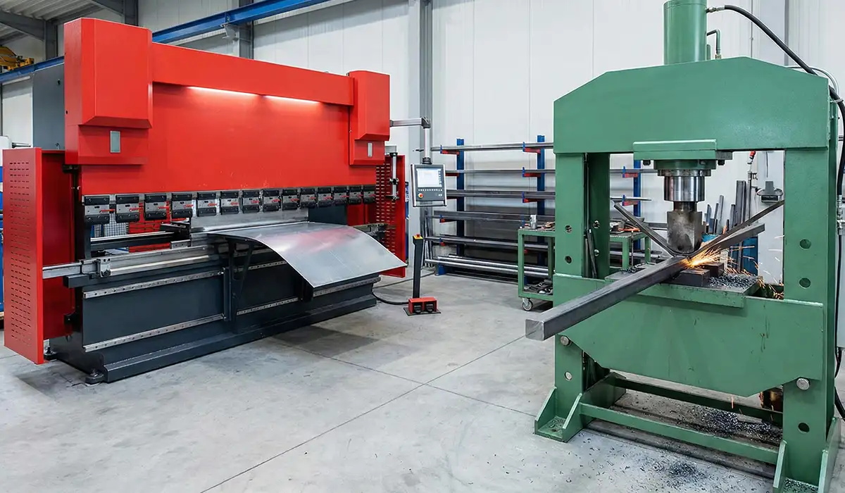
Busbar punching
For connecting busbars to each other, busbar punching is used. This device has the following capabilities:
- Ability to work on copper busbars up to size 12×120 mm.
- Hydraulic forward and return system for the cylinders.
- Ability to create holes of 6mm, 8mm, 10mm, 12mm, 14mm, 16mm, 18mm, oval, and custom.
- Punch design is without deflection for easy and reliable operation.
Busbar cutter
This device is used for cutting busbars. This device has the following capabilities:
- Ability to work on copper busbars up to size 12×120 mm.
- Hydraulic forward and return system for the cylinders.
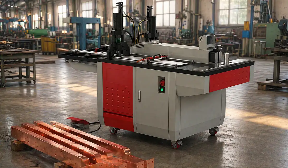
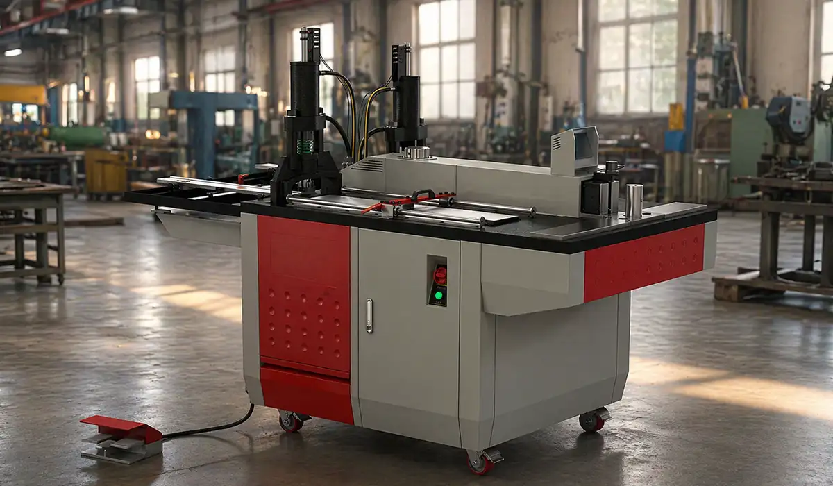
Busbar bending
This device is used for angling and bending busbars. Examples of busbar bending machines are shown in the figures below. This device has the following capabilities:
- Ability to work on copper busbars up to size 12×120 mm.
- Hydraulic forward and return system for the cylinders.
- Bending machine equipped with a digital angle gauge.
If the insights you gained from busbar installation key points were intriguing and informative, exploring a deep dive into busbar bending techniques might be of great interest to you as well.
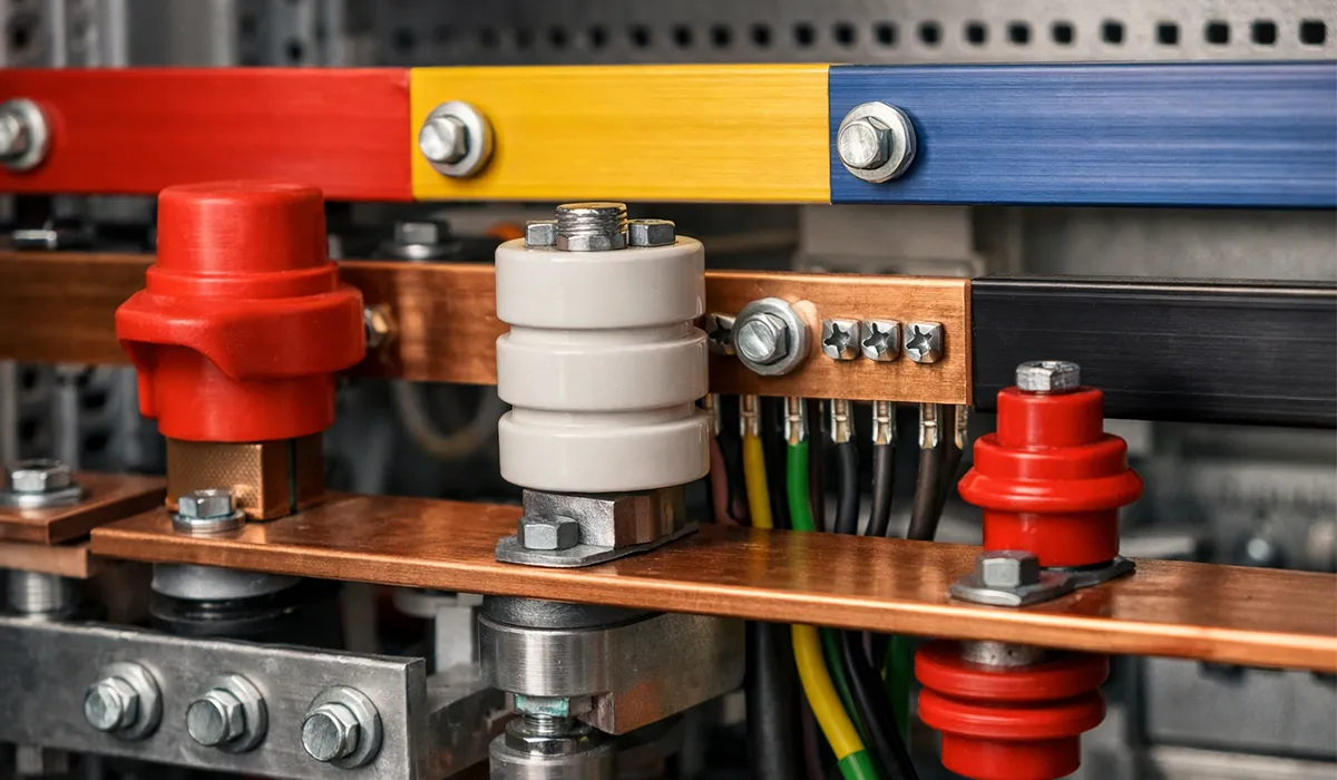
Selecting busbar color
To increase the current-carrying capacity of busbars, they are painted using thermal paints. Painting the busbar is also effective for ease of service, repairs, and troubleshooting. Common colors in panel busbar arrangement are:
- Red (phase one, L1 or R)
- Yellow (phase two, L2 or S)
- Blue (phase three, L3 or T)
- Neutral busbar often black
- Earth busbar, yellow and green
To increase the current-carrying capacity of busbars, they are painted using thermal paints. Using busbar painting will also be effective for ease in service, repairs, and fault clearance. If you enjoyed learning about busbar installation and color coding, investigating operational excellence in metalwork for electrical systems might also offer a similarly engaging and informative experience. essential.
Conclusion
Insulators are used to isolate conductors from the panel body, while creepage distance and air clearance define key insulation paths that are strongly influenced by contamination and environmental conditions. Busbars, as the main conductors for collecting and distributing electrical energy, are selected and installed based on current capacity, material behavior (copper versus aluminum), temperature limits, and mechanical constraints. Proper punching, cutting, bending, and standardized color identification support safe assembly and reliable maintenance. Use these criteria and stated limits when designing, selecting, and installing busbars and insulators in panels and substations.