
Flow Measurement
There are various methods for measuring flow. In this article, we discuss flow measurement methods using physical devices.
Direct method: This method is an accurate approach for calculating fluid flow, but its application is limited (a laboratory method). It is used for calibrating flowmeters. For example, in water treatment plants, technicians use direct measurement by collecting fluid in a calibrated tank over a precise time interval to verify the accuracy of installed flowmeters.
Further exploration of Flow Measurement can be found in the following recommended reading.
Prefer listening? You can play the audio version of the rest of this article below.
Indirect Method
- A) Based on local pressure difference in the fluid flow (in pipes that have local resistance along their length).
- Orifices: Have contraction and jetting. Commonly used in natural gas pipelines where flow rates need monitoring without excessive equipment cost.
- Converging-diverging parts, Venturi tube: In this method, energy loss is minimized compared to orifices. Venturi tubes are frequently used in large water distribution systems where pressure recovery is important.
- Elbow meter: In this method, energy losses appear as a pressure drop. This simple method utilizes existing pipe elbows, making it cost-effective for retrofit applications.
- B) Using devices that measure flow velocity at the cross-section
- Flow measurement through the velocity profile
- Local velocity in the cross-section
- C) Using obstructions inside the flow
- Turbine flowmeters
- Drag-type flowmeters
Variable Area Flow Meters
Variable area flow meters (Constant-Differential-Head) measure the fluid flow rate based on the displacement of a measuring body whose movement is proportional to the fluid flow rate.
Types of Variable Area Flow Meters
In variable area flow meters, as the flow rate increases, the flow passage area increases, and as a result, the pressure drop remains practically constant. The weight of the measuring body acts as the balancing force. The measuring body may be in the form of a plumb bob, a piston, or various floats. Accordingly, the three main types of variable area flow meters are:
- Rotameter
- Piston type
- Float type
This article serves as a valuable resource for those seeking detailed information on Types of Variable Area Flow Meters.
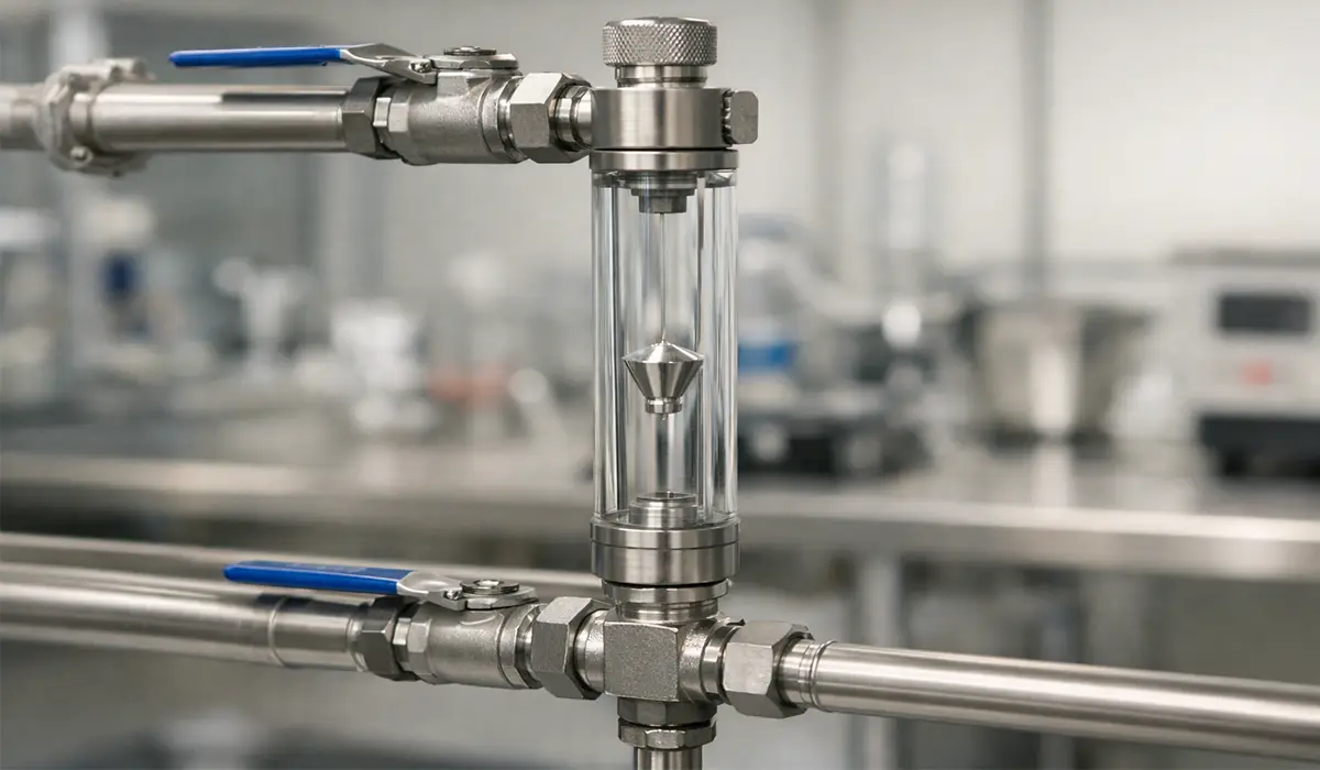
Rotameter-Type Flow Meter
This device, which is widely used mostly in educational and research centers, is often used to measure the flow rate of fluids with a uniform flow and gradual flow-rate changes. A typical application is in laboratory chemical reactors where precise gas flow control is needed, such as measuring oxygen flow in fermentation processes at 0.5 to 5 liters per minute.
A variable area flow meter, or rotameter, is another flow measurement method that consists of a chamber whose cross-section increases from bottom to top. The greater the flow rate (volumetric flow), the higher the float sits.
The force exerted by the fluid on the float pushes it upward, while the float’s weight pulls it downward. At one point, these two forces balance. The float position and the connected indicator are proportional to the measured flow rate.
Rotameters should mostly be used for measuring clean fluids or fluids with few impurities; the measurement range for glass rotameters is within the pressure range (0.6 MPa). You can use a rotameter directly as an indicator in gas analyzers and other similar devices.
Rotameters generally consist of the following two parts:
- A vertical glass tube whose diameter gradually increases from bottom to top.
- A plumb bob or float located inside the glass tube that can freely move up or down.
The upper collar of the float (rotameter index) has oblique slots. This causes the float, as fluid passes through the pipeline, to both move upward and rotate about its axis. With this action, the float stays centered in the rotameter and, due to flow changes, can move vertically up or down in the center of the glass tube.
The float (plumb bob) position at any state indicates a specific flow rate. To determine the amount of fluid passing per unit time, it is sufficient to scale the outer surface of the glass tube and, by calibrating the graduations, determine the fluid flow rate.
The alignment of the index line on the float with any graduation on the glass tube, calibrated in liters or cubic meters per hour, indicates the fluid passage per unit time. In some rotameters, the float does not rotate and is metallic, but necessary provisions are made so that the float remains centered in the rotameter.
The rotameter housing can be made of glass or metal. When the measured fluid is flammable or hazardous, use a metal housing. In this case, the float is not visible, and other methods must be used to detect its position.
Models with a glass tube are referred to as direct viewing rotameters. Models with a metal housing are equipped with an electrical or pneumatic transducer.
The rotameter length indicates its sensitivity. The longer it is, the more accurately it can be graduated, and for specific flow changes the float displacement will be greater. This flow measurement method is simple and has few parts and accessories; moreover, its wear is negligible.
For a comprehensive understanding of Rotameter, we highly recommend reviewing this article.
Piston-Type Flow Meter
In piston-type variable area flow meters, the float is a piston-like part. This piston moves vertically inside a sleeve or cylindrical tube called a cylinder. This cylinder has an inlet opening with a circular cross-section and an outlet opening with a square or rectangular cross-section.
The outlet opening of the cylinder acts like an orifice with a variable flow area. The orifice diameter is selected based on the flowmeter capacity. The piston weight is adjusted using suitable weights for the desired measuring range.
A connecting rod links the piston to the core of an electrical current transducer. The fluid entering the flow meter lifts the piston and thus opens the outlet. The outlet area opens to the extent required to allow the desired fluid flow.
The square or rectangular outlet cross-section creates a linear relationship between piston displacement and fluid flow rate.
Float-Type Flow Meter
In float-type flow meters, the metering body is a type of float. The orifice of this flow meter has a passage whose cross-sectional area increases from bottom to top.
This passage is integrated into a housing. In this type of flow meter, the passage plays the role of the rotameter glass tube. The only difference between this passage and the rotameter glass tube is that its length and diameter are approximately the same, whereas in a rotameter the measuring tube length is much greater than its diameter. It should be noted that float-type and piston-type flow meters have more limited applications than rotameters.
Measuring Flow via Pressure
Measuring flow via pressure is one of the widely used methods. Measuring flow with a differential pressure flowmeter is based on measuring velocity, and velocity measurement usually requires mechanical and moving components, which leads to wear, and therefore the need for repair and servicing.
By measuring flow via pressure, moving mechanical components can be eliminated, and the durability and strength of the measuring device can be increased. In addition, such a design is usually simpler and cheaper. A pressurized fluid moving in a pipe has three types of energy: Potential energy, kinetic energy, and pressure energy.
The potential energy of a fluid is measured relative to a reference level, and if the pipe is horizontal, it is constant. Kinetic energy is due to fluid motion and flow and is proportional to the square of velocity. Pressure energy is due to fluid pressure and is stored in the fluid as pressure.
Bernoulli’s law, which is essentially the principle of energy conservation in fluids, expresses the relationship of these energies as follows: The sum of kinetic energy, potential energy, and pressure energy in a fluid is constant. Therefore, with constant potential energy, if kinetic energy increases, pressure energy decreases. In other words, if you increase fluid velocity (kinetic energy), pressure (pressure energy) decreases.
Further exploration of Pressure measurement can be found in the following recommended reading.
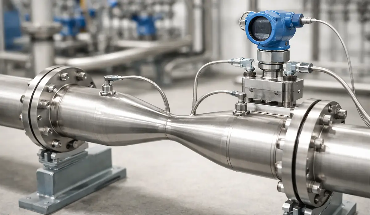
Venturi Flowmeter
A general schematic of a Venturi-tube flowmeter is shown in typical engineering references. In this design, an obstruction in the form of an orifice is created in the flow path inside the pipe. The volumetric flow rate is constant throughout the pipe, so the fluid velocity immediately after passing through the orifice increases to keep the volumetric flow rate constant. This means the kinetic energy increases on the downstream side of the orifice, and Bernoulli’s principle requires the downstream pressure to decrease. This creates a pressure difference across the orifice. The Venturi tube disturbs the flow and causes less energy loss than the other two examples, but its cost is higher. For instance, in a 6-inch water pipeline flowing at 500 gallons per minute, a Venturi tube might show a pressure differential of 10 psi, which can be directly converted to flow rate.
If you are looking for more information about Venturi Flowmeter, it is recommended not to miss reading this article.
Measuring Flow via a Pitot Tube
A pitot tube is one of the most accurate methods for measuring velocity. Pitot tubes are used to measure local velocity and local fluid pressures. They are also used to measure fluid flow rates in research studies and similar applications. A special type of pitot tube is used to measure aircraft airspeed – for example, commercial aircraft like the Boeing 737 use pitot-static systems to measure airspeed ranging from 150 to 500 knots.
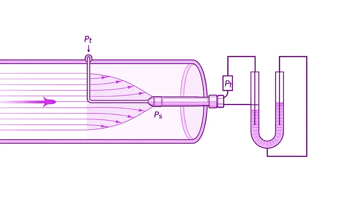
Essentially, a pitot tube measures velocity and flow rate by determining the difference between total pressure, or impact pressure, and static pressure. This pressure difference, called kinetic pressure, is related to velocity through a relationship derived from Bernoulli’s law.
So, to find dynamic (kinetic) pressure and thus obtain velocity at a specific point on the flow streamlines, it is necessary to determine the difference between static pressure and total (impact) pressure.
Total pressure is measured by a pressure tube, installed so that its opening faces the flow streamlines, and static pressure is measured by one or more ports installed in the wall of the flow pipe.
Since the fluid velocity at a given point is obtained using the pressure difference (Pt-Ps), the sensing heads for total and static pressure must be connected to a liquid-column low pressure device or a differential manometer. In this setup, the rise of the liquid level is determined under the force applied by the fluid.
Further exploration of Pitot Tubes can be found in the following recommended reading.
Types of Pitot Tubes
In the Bernoulli relation, one parameter relates to the density of the flowing fluid in the pipe and another parameter relates to the density of the manometer fluid. Therefore, to increase calculation accuracy as much as possible, the density of both fluids must be determined precisely. A more complex type of pitot tube is the combined pitot tube or the pitot-static tube.
A combined pitot tube has ports with fixed relative positions and is used to measure static pressure and impact (total) pressure. These ports are collectively housed in a single casing and placed in the flow path. This assembly is called a probe.
All types of pitot tubes have error in determining dynamic (kinetic) pressure. For this reason, a correction factor called the coefficient of discharge is considered in the Bernoulli relation and is denoted by C or CD.
This coefficient is obtained experimentally by calibrating the device and differs for different pitot tubes. In velocity calculations, where the fluid velocity is less than 0.2 Mach, assume that the fluid is incompressible. Among pitot tubes, the pitot-static tube is the most common type used in research and industrial centers.
If you are looking for more information about Pitot tube, it is recommended not to miss reading this article.
Pitot Tube Operation
The pitot probe is mounted on a support rod and its opening is placed in the flow. The total-pressure sensing opening is located at the spherical head of the probe, and the static-pressure sensing holes are positioned on the side surface of the probe as a set of discontinuous slots.
The impact (total) pressure port senses impact pressure, and the static pressure port senses static pressure. Each transmits the sensed pressure through passages inside the probe to a measuring device, where the differential pressure Pt-Ps is determined. Ps is the static pressure on the flow streamline, and Pt is the measured total pressure.
There is a region on the probe surface where L/d = 3, where L is the distance from the tip hole to the side holes and d is the probe diameter. At that point, you can consider the local pressure P equal to the static pressure Ps.
This is why static-pressure sensing ports are placed there. Sometimes, instead of discontinuous slots, separate holes are made around the cylindrical casing to sense static pressure.
Important Notes About the Pitot Tube
- One advantage of the pitot-static tube is its low error when the probe axis deviates slightly from the flow direction. The angle between the probe axis and the flow direction is known as the angle of attack or yaw angle. If the angle is small, total and static pressures change at approximately the same ratio, and their dynamic pressure difference remains nearly constant up to an angle deviation of 16 degrees.
- When using a pitot tube, remember that a large-diameter probe at its location can disturb the flow distribution. On the other hand, since very small-diameter pitot-static tubes rarely have sufficient accuracy, pitot-simple tubes are typically used for velocity measurement. In this type, the total-pressure (impact) opening is between 0.05 and 1 millimeter, and static pressure is sensed using a port or orifice in the pipe wall.
- When fluid velocity is between 5 and 25 meters per second, the pressure difference is small. Due to difficulties measuring velocity and flow rate using pitot tubes or liquid manometers at low gas velocities, gas meters such as vane (blade) meters, hot wire, hot film, heated thermocouples, and thermistor gas meters are typically used.
- Local (point) velocity varies across the pipe cross-section. Velocity is maximum on the pipe axis, and decreases as you approach the wall.
- To determine flow rate, the average fluid velocity must be determined. The average velocity is determined by a method known as obtaining average velocity by moving the pitot tube opening along a diameter of the flow cross-section. For this, divide the pipe cross-section diameter into n equal parts, place the pitot tube total-pressure opening at each position, and obtain the velocity at each point. Continue to the final division to obtain the various velocities along the diameter. Then, by averaging these velocities, determine the average velocity.
- Determining velocities at each point is done assuming the velocity remains constant throughout measurement and equals the measured value. Although the pitot tube has many advantages, using it to determine average velocity has limitations, including the long time required for calculations and the need for very precise instruments to measure dynamic pressure.
- In gases where velocity and pressure change rapidly, the gas meters mentioned above are used instead of pitot tubes, because it has been proven in practice that pitot tubes are not suitable for measuring sudden changes in velocity and pressure.
- In the Pitot-Prandtl tube, you can consider the pitot and static tubes as one. In its cross-section, there are 8 holes used to measure static pressure.
Measuring Flow with a Pitot Meter
- Insert the pitot meter into the circuit. This device includes a network of pipes in which water circulates via a pump connected to a tank, and along the piping there are an orifice, a nozzle, a converging-diverging part, and a pitot meter. You can connect upstream and downstream of each of these parts to two piezometer tubes installed on the device and obtain their pressure difference. Before the test, the piezometer must be vented.
- To vent, first open the upper valve of the piezometer; pressure from below causes the water level to rise and expel air from the upper tank valve. After complete venting, close the tank valve and re-inject compressed air.
- This compressed air applies pressure from above onto the fluid surface. If you use compressed air, you would need a tall tube, because for each 1 atmosphere of pressure difference you need 10 meters of tubing, which is practically impossible.
- Since the basis of flow measurement is pressure difference and this air applies equal pressure to both sides of the piezometer tube, it will not cause measurement error. Turn on the pump and, using the valve in the line, introduce various flow rates into the network and measure the volume of flowing fluid using the level indicator.
- When the water level reaches zero, start the stopwatch, and stop it when it reaches ten. Then the fluid volume is 10 liters. By dividing volume by discharge time, the actual flow rate is calculated. This is repeated several times by opening the water valve. For each valve opening, the flow rate and head are measured once. The following are causes of errors in the test:
- Time measurement error
- Error in reading the manometer water level
- Additional equipment installed on the pipe in the lab, to some extent
- Air inside the piezometer tubes used for pressure measurement
The industrial application of the pitot tube is measuring local flow velocity and, consequently, measuring flow rate. Since the distance of the pitot opening can vary from the pipe surface or the free liquid surface in open channels, it can be used to study velocity distribution in the boundary layer.
One common application of the pitot tube is measuring aircraft speed, but since compressibility effects also appear there, a larger correction factor must be applied.
The advantage of the pitot tube is that it is not sensitive to deviation from the flow direction, and if the deviation from the flow direction is small, the resulting error will be only a few percent (two or three percent), which is very important.
Measuring Flow via a Pressure Transmitter
A pressure transmitter is a type of electromechanical equipment (or fully electronic) for signal processing, meaning it acts as an interface between the process and the control system. The electrical circuit or electromechanical assembly of a transmitter is often located within the sensor itself or together with it.
If you consider the transmitter separately, it is then called a transducer and is not limited to sensors; it may also be in a signal path between a controller output and the final control element such as a control valve. A transmitter converts a measured signal sample, usually in millivolts, differential pressure, or mechanical displacement, into a standard signal. By control signal, we mean the signals entering the controller and leaving it.
Standard control signals include:
- Voltage: 0-1, 0-10, ±10, ±5
- Current: 4-20mA
- Pressure: 3-15 psig
Determining Local or Average Velocity in a Cross-Section
In this method, the passing fluid velocity is determined at each cross-section, and the complete velocity profile is drawn (the velocity profile is determined by injecting colored fluid into the flow to make the fluid velocity visible). Since this method is time-consuming, it is used only in precise research work. For example, researchers studying turbulent flow in heat exchangers use laser Doppler velocimetry to map velocity profiles across pipe diameters of 50 to 200 millimeters.
Volumetric Meters
Volumetric flow meters that measure the total fluid volume have a transducer and a recorder or indicator to display the total fluid volume. In these transducers, the speed of movement of a sensing element is used, where the speed of this sensing element is proportional to the volumetric flow rate. Two main types in this category are:
Turbine Flowmeter (Propeller Type)
The angular speed (rotational speed) of the propeller is proportional to the fluid flow velocity and thus proportional to volumetric flow rate. The number of propeller rotations is determined by a recorder or calculator, and the total passed flow is shown by an indicator. These devices come in two types: dry meter and wet meter. The wet type has advantages over the dry type, including no need for additional parts, simplicity, and smaller dimensions. However, these devices perform well only when clean water passes through them, which is why dry-type devices are generally more practical.
When a turbine is placed in the path of a moving fluid, since the other side of the turbine is connected to a magnetic core and a detector coil is located opposite the core in the outer body of the flowmeter, the passage of the core past the coil induces electromotive force in it. As the fluid speed increases, the turbine rotation and thus the magnetic core rotation speed increase, and a larger electromotive force is induced in the coil. In newer designs, the core and detector coil are built so that fluid speed is converted to pulse frequency, and by counting pulses and averaging via relevant circuits, fluid velocity and thus volumetric or mass flow are obtained.
The main drawback of these flowmeters is that they disturb and interfere with the natural movement of the fluid and may themselves alter the measured flow. Corrosion and the need for repairs are disadvantages, and these flowmeters are not suitable for measuring low flows.
These flowmeters are suitable for measuring the flow of clean fluids, and if the fluid contains suspended or sticky particles and impurities, measurement will face problems. Also, this flowmeter must be installed in straight pipe runs. A typical installation requires 10 diameters of straight pipe upstream and 5 diameters downstream for accurate readings.
For a comprehensive understanding of Volumetric Meters, we highly recommend reviewing this article.
Positive Displacement Flowmeter
Flow meters with a positive displacement element measure the total volume of diesel fuel flow, crude oil, gasoline, and similar liquids with higher accuracy than propeller or turbine types. For example, retail gasoline pumps at service stations use positive displacement meters to accurately measure volumes from 0 to 200 liters with an accuracy of ±0.5%.
The accuracy of these measuring devices is most affected by fluid density and flow rate, and is usually obtained through experience at fixed and specified flow rates. Increasing density and flow rate causes a higher static pressure drop. Therefore, pressure drop is usually used to determine the capacity of the measuring device. These flow meters are categorized as follows:
- Reciprocating piston type
- Nutating disc type
- Rotating lobe type
- Rotating vane type
If you want to add a third and secondary category, you can refer to electromechanical flow meters. These devices are often used to measure speed changes in turbulent flows and are usually used as sensing elements. When these cups are placed in the fluid flow, they begin to rotate due to the applied force.
Using the electrical circuit in the device, the number of rotations, which is proportional to speed, is converted to a signal. The number of signals in a specific time interval is a function of speed. By placing the device in a fluid with known speed, it is calibrated and adjusted. Air speed is measured with a cup or vane anemometer. In this device, speed may be measured directly by turning a generator, or the number of rotations may be obtained by turning a counter.
By designing blades with low inertia and using precise bearings and optical tachometers that do not consume power to rotate, it is possible to build anemometers suitable for very low air speeds. These devices are so sensitive that they even show airflow caused by heat emitted from the human body.
Ultrasonic Flowmeter
Using an ultrasonic flowmeter to measure flow is one of the widely used methods. Ultrasonic transmitters and receivers are used, where the transmitter is on one side of the pipe and the receiver is on the other side. The wave transit time through the pipe depends on pipe characteristics and the flowing fluid material, which is constant in a specific measurement and is accounted for during device calibration. This transit time also depends on the flow direction and fluid speed in the pipe. Therefore, by measuring the time interval between sending the wave by the transmitter and receiving it by the receiver, you can obtain fluid velocity and thus the flow rate.
The main advantage of these meters is that they have no effect on the measured quantity, and they also have good accuracy and speed. Of course, this advantage comes at the cost of higher expense and greater complexity. For example, clamp-on ultrasonic flowmeters are popular in municipal water systems for pipes ranging from 1 inch to 120 inches in diameter.
In ultrasonic flowmeters, the difference in time resulting from the forward and return travel of the sound signal within the fluid is measured. If a sound signal at constant speed V is sent from point A to B, the forward and return speeds of the signal, assuming equal path lengths, are V – V1 and V + V1. This speed difference in the forward and return paths is converted into a time difference, and if you measure this difference, measuring fluid speed inside the pipe becomes possible. With this speed, you can obtain the water flow rate.
This article serves as a valuable resource for those seeking detailed information on Ultrasonic Flowmeter.
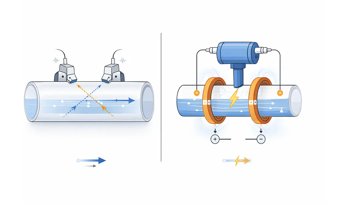
Electromagnetic Flowmeter
An electromagnetic flowmeter is only suitable for measuring electrically conductive and electrolyte fluids such as ordinary water. This flowmeter operates based on Faraday’s law. Ve = BLV, where V is velocity, L is line length, and B is magnetic field intensity. Fluid movement cuts magnetic field lines, and the induced voltage on the conductor depends on fluid velocity; in fact, this flowmeter measures fluid velocity. Because the field and length are constant, fluid flow depends only on the velocity of the conductive fluid. Here, the pipe carrying the fluid must be made of non-magnetic and non-electrical materials. In wastewater treatment plants, electromagnetic flowmeters commonly measure slurry flows from 10 to 5000 gallons per minute with conductivities as low as 5 microsiemens per centimeter.
Comparison of Flowmeter Technologies
| Characteristic | Ultrasonic | Electromagnetic | Turbine | Positive Displacement |
|---|---|---|---|---|
| Accuracy | ±2.5% | ±0.5% | ±1% | ±0.5% |
| Pressure Drop | None | None | Medium | High |
| Fluid Requirements | Clean, uniform | Conductive (>5 µS/cm) | Clean only | Any viscosity |
| Installation Complexity | Moderate | Moderate | High (straight runs required) | Low |
| Maintenance | Low | Low | High (moving parts) | Moderate |
| Cost (Large Sizes) | Low to Medium | High | Medium | High |
| Typical Applications | Water distribution, large pipes | Wastewater, slurries | Clean liquids, gases | Custody transfer, fuel dispensing |
Difference Between Ultrasonic and Electromagnetic Flowmeters
Advantages of ultrasonic flowmeters:
- Does not create any pressure difference.
- Installation conditions are relatively easy.
- Increasing pipe size does not affect total cost significantly.
Disadvantages of ultrasonic flowmeters:
- Not very accurate (about 2.5%).
- Calibration must be performed on-site, which will be accompanied by error.
- The fluid must be completely uniform and must not contain impurities.
- Installation requirements are restrictive; for accurate measurement, the flow must be free of any disturbance.
- System accuracy changes over time due to strong dependence on environmental and installation conditions, and in the long term the error may sometimes exceed 10%.
Advantages of electromagnetic flowmeters:
- Does not create any pressure difference in the path.
- Has relatively desirable accuracy (about 0.5%).
- Imposes minimal installation limitations on the line.
- Calibration is performed at the factory, which can reduce error to a desirable level.
Disadvantages of electromagnetic flowmeters:
- Price increases sharply in larger sizes.
- Not usable for fluids with electrical conductivity less than 5 microsiemens per centimeter.
Conclusion
This text reviewed five practical flow measurement approaches, ranging from variable area flow meters and pressure-based methods to volumetric, ultrasonic, and electromagnetic flowmeters. Each method has its own operating principle, installation constraints, and limitations related to accuracy, pressure drop, fluid cleanliness, and conductivity. Choosing the right option depends on the process conditions and the required measurement reliability. For selection and implementation, evaluate the fluid properties and installation conditions and match them to the appropriate meter type.
Frequently Asked Questions
What are the main categories of flow measurement methods?
Flow measurement methods include variable area meters (rotameters), pressure-based methods (Venturi, pitot tubes), volumetric meters (turbine, positive displacement), ultrasonic flowmeters, and electromagnetic flowmeters.
How does a rotameter work?
A rotameter uses a tapered vertical tube with a float inside. As flow increases, the float rises higher in the tube where the cross-sectional area is larger, balancing the upward fluid force with the float’s weight to indicate flow rate.
What is the principle behind pitot tube measurement?
Pitot tubes measure the difference between total pressure and static pressure to determine dynamic pressure, which is then used to calculate fluid velocity using Bernoulli’s equation.
Which flowmeter type offers the highest accuracy?
Electromagnetic and positive displacement flowmeters typically offer the highest accuracy at approximately ±0.5%, while ultrasonic meters are less accurate at around ±2.5%.
Can electromagnetic flowmeters measure all types of fluids?
No, electromagnetic flowmeters only work with electrically conductive fluids having conductivity above 5 microsiemens per centimeter, such as water, wastewater, and electrolyte solutions.
What are the main advantages of ultrasonic flowmeters?
Ultrasonic flowmeters create no pressure drop, have relatively easy installation, and their cost does not increase significantly with pipe size, making them ideal for large diameter applications.
Why do turbine flowmeters require straight pipe runs?
Turbine flowmeters need straight pipe sections (typically 10 diameters upstream and 5 downstream) to ensure uniform flow profiles and eliminate flow disturbances that would affect measurement accuracy.


