
I work with control panels every day. When a drive trips or a PLC freezes because of noise, production stops and everybody looks at the panel. This short guide is the checklist I wish I had on my first projects. It follows the IEC 61000 brief and keeps the SEO headers/keywords you asked for.
IEC 61000 series overview
Think of the EMC standards in two layers. The IEC 61000‑4‑x “Basic” parts describe how to test. The “Generic” parts say what level you must meet. For panels without a product standard, we usually apply:
• IEC 61000‑6‑2 for immunity (how robust the panel must be in an industrial site).
• IEC 61000‑6‑4 for emissions (how quiet the panel must be).
Industrial plants are noisy by nature—big transformers, long cables, and fast switching—so Class A normally fits.
IEC 61000‑6‑2 immunity requirements
Before any test, agree on performance criteria with the client:
A = no upset during/after test; B = temporary upset allowed but auto‑recovery; C = function may stop but can be restored.
Typical levels mapped to IEC 61000‑4‑x:
• ESD (‑4‑2): 4 kV contact, 8 kV air.
• Radiated RF (‑4‑3): 10–30 V/m.
• EFT/Burst (‑4‑4): 2–4 kV on power.
• Surge (‑4‑5): 1–4 kV L‑L, 2–4 kV L‑PE.
• Conducted RF (‑4‑6): 3–10 V, 150 kHz–80 MHz.
• Power‑freq magnetic field (‑4‑8): high class in heavy areas.
• Dips & interruptions (‑4‑11): defined residual voltages and times.
Mapping 6‑2 to 4‑x tests
Your plan should name every port, the cable length, and the operating mode you will exercise for each test. Don’t forget “worst case” settings—for example, a VFD at the speed where it radiates the most.
IEC 61000‑6‑4 emission limits (CISPR 11 Class A)
Most panels are checked against CISPR 11 (ISM) Class A. We look at:
• Conducted emissions: 150 kHz–30 MHz with a LISN and EMI receiver.
• Radiated emissions: 30 MHz–1 GHz (and sometimes higher) in a chamber.
Class A is fine for industrial locations; for residential, additional measures are usually required.
Test setups for emissions (quick view)
Conducted: the EUT sits on an 80 cm non‑conductive table over a ground plane; the LISN feeds power to the EUT and to the receiver.
Radiated: the EUT turns on a table while an antenna scans; we adjust orientation and cabling to catch the peak.
ESD, RF, EFT, surge — what actually works
• ESD: place TVS diodes at each exposed I/O and bond their ground pad straight to the metalwork (short, wide path).
• EFT/Burst: snubbers or MOVs on coils/relays; shielded entries with proper 360° clamps.
• Surge: coordinate MOVs/TVS with upstream SPD; keep return paths short.
• RF immunity: keep enclosure seams tight with EMC gaskets; avoid long shield “pigtails.”
Voltage dips and interruptions (‑4‑11)
PLCs and drives hate dips. Add DC ride‑through (bulk cap or DC UPS) or stagger the start‑up to prevent nuisance trips after power blinks.
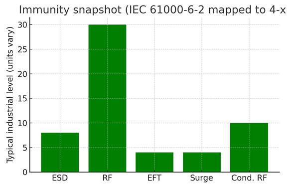
Figure: Green immunity levels for key IEC 61000‑4‑x tests (illustrative).
| Category | Standard | Frequency / Focus | Notes |
| Emissions | IEC 61000‑6‑4 / CISPR 11 Class A | CE 150 kHz–30 MHz; RE 30 MHz–1 GHz+ | Industrial Class A; LISN and chamber |
| Immunity | IEC 61000‑6‑2 via 4‑2/3/4/5/6/8/11 | ESD, RF, EFT, Surge, Cond. RF, PF magnetic, Dips | Define criteria A/B/C; test worst‑case modes |
EMC test plan and setup (template)
1) Freeze the exact hardware/firmware and operating modes.
2) List ports and cable types/lengths; pick representative samples.
3) Map each test to criterion A/B/C and expected behavior.
4) Prepare the CE technical file (reports, photos, schematics, risk assessment).
Wiring and cable routing rules
• Separate power, control, and sensitive analog/communications.
• Terminate shields 360° to the enclosure wall with clamps; no long tails.
• Bonding: scrape paint, use short/wide straps to a common ground bar.
• Filters: line filter at the panel inlet; ferrites on noisy devices and I/O.
Ferrites, chokes, and filters (quick picks)
• VFD input: a Class A line filter with a very short earth bond to the back‑plate.
• I/O and DC lines: common‑mode chokes for external cables; tiny ferrites on IC supply pins for differential noise.
Shielding, grounding, bonding practices
Use conductive gaskets on doors and keep both hinge and latch sides bonded. Partition plates should have low‑impedance bonds to the ground bar so currents don’t wander.
VFD noise and mitigation
Expect the drive to be your loudest neighbor. Use shielded motor cables with 360° terminations at both ends, add dV/dt or sine‑wave filters for long runs, and keep motor leads well away from sensitive I/O—cross at 90° when paths must meet.
EU CE documentation workflow
• Keep drawings, BOM, firmware IDs, and reports in the technical file.
• Sign the Declaration of Conformity when the evidence is complete.
EU vs US EMC compliance (snapshot)
EU/International: immunity required (6‑2); emissions via 6‑4/CISPR 11.
US/FCC: emissions via Part 15 Class A (digital) or Part 18 (ISM); immunity not mandated but wise for reliability.
Common EMC failures and fixes
• Radiated peaks from doors/seams → fit gaskets, tighten bonds, shorten cables.
• Conducted fails (150 kHz–10 MHz) → upgrade the line filter and its earth bond; add ferrites near noisy loads.
• EFT/Surge resets → add MOVs/TVS at I/O and mains entry; shorten returns; snub coils.
• Dip trips → provide ride‑through energy or a small DC UPS.
FAQ: quick answers
Which tests apply to panels?
→ 6‑2 immunity + 6‑4 emissions using the 4‑x methods.
What goes in CE docs?
→ Risk assessment, reports, drawings, user manual, DoC.
CE and FCC together?
→ Yes—design for CISPR 11 Class A and check FCC Part 15 Class A.


