






If you’d rather listen than read, feel free to play the audio file below for the rest of this article.
Rated Peak Withstand Current: What the Switchgear Must Survive
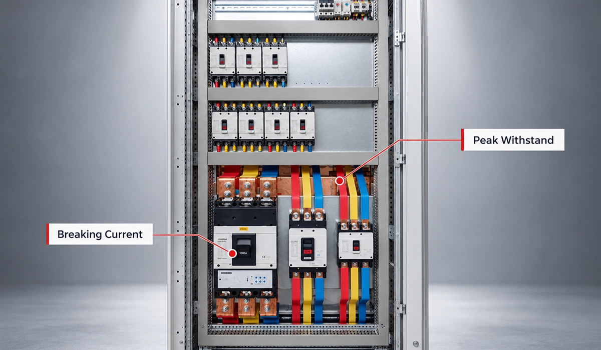
The rated peak withstand current belongs to the switchgear and its main conductors, not to the breaker. ABB’s 2001 ZS1 manual makes that plain by calling it the rated impulse current of the main conductor: 125 kA at 12 kV.
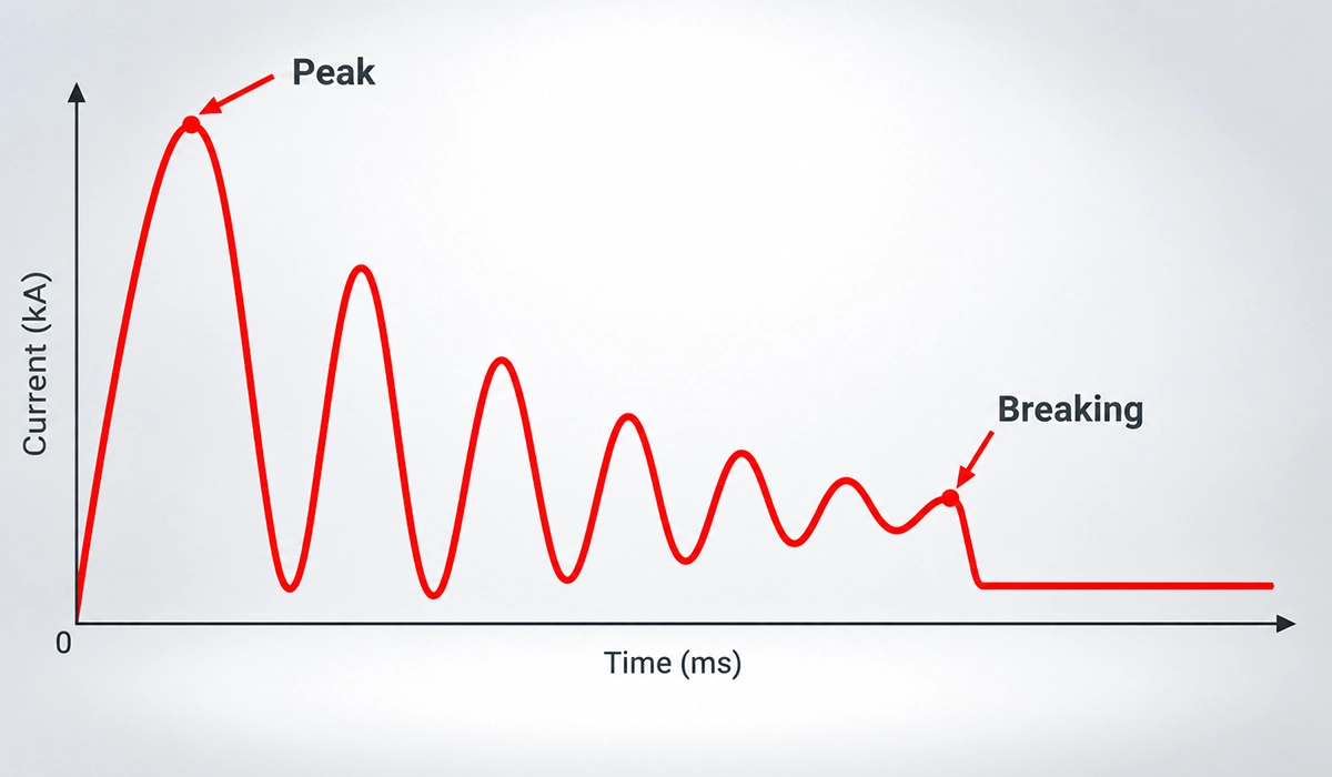
It is the highest instantaneous short-circuit current the installation is rated to withstand. At that instant the electrodynamic forces between conductors are at their greatest, so this is a mechanical rating as much as an electrical one.
That puts the figure on the busbars, their supports and joints, and everything else fixed in the current path. The breaker can be the best in the line-up and still add nothing to it.
ABB’s ZS3.2 table gives up to 80 kA, with 100 kA available on request.
On projects, the common mistake is to read the breaker’s datasheet and assume the panel matches it. Check the peak figure against the calculated peak fault current as a separate line item.
Ratings like these are defined and tested under recognised standards, not left to the manufacturer’s judgement. For the full picture, see our overview of switchgear standards and how they apply to busbar systems.
Short Circuit Breaking Current: What the Breaker Must Interrupt
The short circuit breaking current is attached to one device, the circuit-breaker: it is the fault current that breaker is rated to interrupt. ABB’s ZS3.2 lists up to 31.5 kA, with 40 kA on request.
ABB spells out the ownership. Both manuals list the breaking value “of the circuit-breaker”, a qualifier the peak row never carries. In ZS1 the figures are 50 kA at 12 kV and 40 kA at 17.5 kV.
Interrupting is a different job from withstanding. The breaker has to open and clear the fault, while the conductors only have to hold together as it flows. How the breaker does that is a separate subject.
That difference is why a strong breaker cannot rescue weak busbars. A breaker that clears the fault still lets the peak pass through the conductors first.
A breaker is one layer of a wider protection scheme, and it only acts after a fault has begun. Our guide to overcurrent protection methods explains how the layers fit together.

Side by Side: Real Values
Across ABB’s three data sets, dividing the peak figure by the breaking figure gives about 2.5 every time.
| Design | Rated voltage | Rated peak withstand current | Breaking current (circuit-breaker) | Short-time current | Peak ÷ breaking |
|---|---|---|---|---|---|
| ZS3.2 | 36/40.5 kV | Up to 80 kA (100 kA on request) | Up to 31.5 kA (40 kA on request) | 31.5 kA, 3 s | ≈2.5 |
| ZS1 | 12 kV | 125 kA | 50 kA | 50 kA, 3 s | 2.5 |
| ZS1 | 17.5 kV | 100 kA | 40 kA | 40 kA, 3 s | 2.5 |
Treat that ratio as arithmetic on ABB’s values, not as a design rule. ABB publishes the figures without saying how one relates to the other, so no rule is claimed here.
For a specifier, the useful habit is to check each column against its own requirement. The peak figure goes against the calculated peak fault current, and the breaking figure against the fault current the breaker must clear.
You can also save a copy for later, which is helpful if you plan to return to this more than once.
Comparing ratings is only useful when the assembly itself has been verified against them. Read our guide to IEC 61439 verification to see what that involves.
Where Else These Numbers Matter
Three more things have to be read against these figures: the instrument transformers, the earthing switch and the short-time rating.
ABB footnotes its withstand ratings with a warning: instrument transformers have their own short-circuit withstand capability, which needs checking separately. In ZS3.2 it sits on both the peak and short-time rows; in ZS1, on the short-time row.
The ZS3.2 earthing switch has a making capacity of 62.5 kA, with an 80 kA design in preparation, so set it beside the panel’s 80 kA peak figure before specifying.
The short-time current rating sits alongside both, and its duration has its own article.
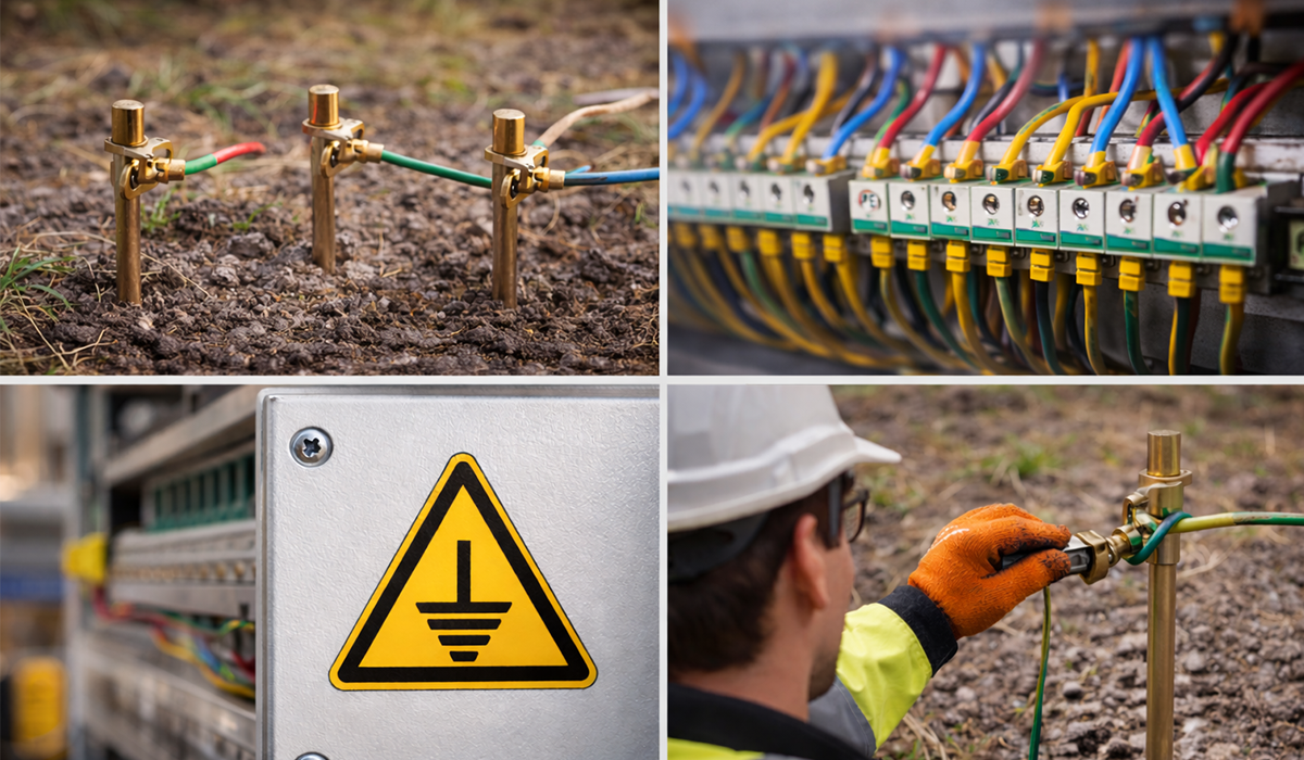
The earthing switch closes onto a path that must carry fault current safely to ground. Our article on earthing systems shows how that path is designed.
Conclusion about peak withstand current
Breaking current asks whether the breaker clears the fault; the rated peak withstand current asks whether the busbars survive it. That is why supports and joints are made to drawing. See our busbar processing machines.
Safe ratings start with busbars made to a controlled, compliant process. Learn more about busbar manufacturing compliance and what it covers.



Rate this article
Choose a rating from 1 to 5 stars.
No ratings yet