
What is an Earthing System?
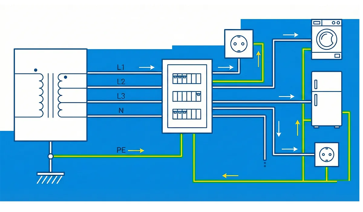
Power distribution systems deliver electricity from power plants to consumers using underground cables or overhead networks. Based on the number of wires, these systems are divided into single-phase two-wire, single-phase three-wire, three-phase three-wire, three-phase four-wire, etc. In this article, we intend to review types of earthing systems. Power distribution systems are classified according to how they are electrically connected to earth (earthing) as follows:
- A) Earthed Power Distribution System: In this system, one point of the distribution system, usually the neutral point, is directly connected to earth, meaning without any significant impedance in its path. If, instead of the system neutral point, one phase is connected to earth, then if one of the phases faults to earth, the voltage of the other phases with respect to earth will be equal to the phase-to-phase voltage.
- B) Unearthed Power Distribution System: In an unearthed distribution system, no point of the system is directly earthed, or one point of it, usually the neutral point, is connected to earth through an impedance that limits earth-fault current. In an unearthed system, if one phase faults to earth, the voltage of the other phases with respect to earth equals the phase-to-phase voltage.
If the information on topic Earthing System was engaging and informative for you, gathering more knowledge about topic Standards on Switchgear could be very exciting.
Types of Conductors in an Earthing System
Neutral Conductor (N)
The neutral conductor is a conductor connected to the neutral point (zero) of the system. This point is usually the star point of the transformer or generator winding. The neutral conductor can participate in transmitting electrical power. In that case, a voltage other than phase-to-phase voltage will also exist in the system. Under special conditions, the neutral and earth may be combined (TNC system).
If you are looking for more information about topic Ground and neutral, it is recommended not to miss reading this article.
PEN Conductor
A conductor that simultaneously performs the functions of protective earth and neutral.
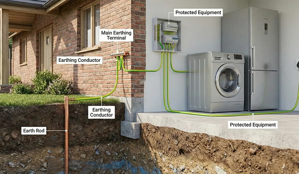
Protective Earth Conductor (PE)
A conductor provided to protect against possible electric shock caused by live parts, and it may be connected to one of the following points:
- Earth electrode
- Main earthing terminal
- Accessible conductive bodies
- The earthing point of the source and/or an artificial neutral
- Conductive bodies that may be unintentionally touched
Further exploration of Protective Earth Conductor can be found in the following recommended reading.
Table 1 – Comparison of N, PE, and PEN Conductors
| Conductor | Full Name | Primary Function | Wire Color (IEC) | Notes |
|---|---|---|---|---|
| N | Neutral | Carries return current; connected to star point of transformer/generator | Blue | Participates in power transmission; must not be used alone as protective conductor |
| PE | Protective Earth | Protects against electric shock by bonding exposed metal parts to earth | Green-Yellow | Does not carry load current under normal conditions; dedicated terminal required |
| PEN | Protective Earth + Neutral (combined) | Performs both N and PE functions in a single conductor | Green-Yellow with Blue marking (or vice versa) | Used only in TN-C systems; min. 10 mm² Cu or 16 mm² Al; RCD not permitted |
Types of Earthing Systems
Usually, to indicate how the distribution system earthing and the consumer’s electrical installation earthing are arranged, two or more Latin letters are used. The first letter indicates how the distribution power system is earthed, and the second letter indicates how the consumer’s electrical installation is earthed. Other letters indicate whether the protective conductor and the neutral conductor are combined or separate in TN systems. The common systems are: TT, TN, and IT.
If the information related to Types of Earthing Systems was interesting and informative to you, researching Protective earth conductor can be very engaging.
Table 2 – Meaning of Letters in Earthing System Designation (IEC 60364)
| Position | Letter | Meaning |
|---|---|---|
| 1st Letter (Power system earthing) | T | Direct connection of one point to earth (Terra) |
| I | All live parts isolated from earth, or one point connected through high impedance (Isolé) | |
| 2nd Letter (Installation earthing) | T | Direct electrical connection of exposed parts to earth, independent of system earth |
| N | Exposed parts connected to the earthed point of the power system (Neutre) | |
| 3rd Letter (TN systems only) | S | Protective and neutral functions provided by separate conductors (Séparé) |
| C | Protective and neutral functions combined in a single PEN conductor (Combiné) | |
| C-S | Combined (PEN) at source side, then separated into PE and N after a split point |
Role of the Protective Conductor in an Earthing System
TT, TN, and IT systems have a protective conductor (PE). All accessible and exposed metal parts of consumer electrical equipment that may become energized during a fault are reliably connected to the protective conductor in these systems. In consumer equipment, there is a dedicated terminal for connecting the protective conductor.
The cross-sectional area of the protective conductor, for copper conductors up to 16 mm², is taken equal to the cross-sectional area of the phase conductors. Like phase conductors, it is protected and installed with care. For several separate circuits, a single protective conductor can be used. In that case, the cross-sectional area of the protective conductor is taken equal to the largest phase conductor cross-sectional area among the circuits.
The enclosure of consumer electrical equipment or parts of its metal structure can also be used as a protective conductor, provided they ensure a reliable electrical connection. Using metal water piping as a protective conductor is not reliable or permissible due to the use of insulating fittings in such pipes. Also, using gas pipes and heating (radiator) pipes as a protective conductor is not permitted.
In fixed and portable wiring, the green-yellow conductor is dedicated to the protective conductor. In each building, a main equipotential bonding conductor must be provided to bond the following conductors:
- Protective conductor (PE) or protective neutral
- Incoming water pipe
- Incoming gas pipe
- Heating supply pipe and HVAC
- Building steel structure and other metal piping, where possible
The cross-sectional area of the equipotential bonding conductor is half the cross-sectional area of the protective conductor, and at least 6 mm². A cross-sectional area greater than 20 mm² for a copper conductor is not necessary for the equipotential bonding conductor.
If the information related to topic Protective Conductor was interesting and informative to you, researching topic Designs Verification can be very engaging.
Table 3 – Minimum Cross-Sectional Area of Protective Conductor (PE) — Copper Conductors
| Phase Conductor Cross-Section (mm²) | Minimum PE Cross-Section (mm²) | Rule Applied |
|---|---|---|
| ≤ 16 | Equal to phase conductor | PE = Sphase |
| 16 | 16 | PE = Sphase |
| 25 | 16 | PE = Sphase / 2 |
| 35 | 16 | PE = Sphase / 2 |
| 50 | 25 | PE = Sphase / 2 |
| 70 | 35 | PE = Sphase / 2 |
| 95 | 50 | PE = Sphase / 2 |
| 120 | 70 | PE = Sphase / 2 |
| Note: For shared PE serving multiple circuits, use the largest phase cross-section among those circuits. Equipotential bonding conductor = PE/2, minimum 6 mm²; max 20 mm² Cu. | ||
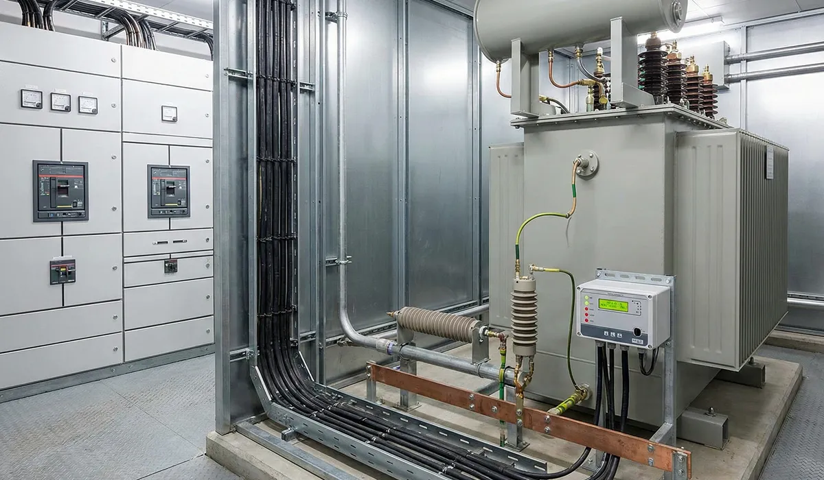
Protective Devices in Earthing Systems
Protective devices commonly used in TT, TN, and IT systems include:
- Overcurrent protective devices, including fuses, miniature circuit breakers (MCB), and automatic circuit breakers with two rated currents (IN) and the operating current (Ia)
- Residual current protection (RCD), designed for earth-fault current. The residual current relay is for AC current and for sinusoidal rectified AC current. Note that an RCD is not for short-circuit protection; for short-circuit protection, an appropriate protective device must be installed. A combined device made from a residual current relay and an automatic breaker (MCB) is available that provides protection against electric shock, short-circuit, and overload.
- An insulation monitoring device, which in IT systems monitors the insulation of distribution conductors relative to earth. If the insulation resistance between line conductors and earth drops below a certain value, an audible or visual warning is issued.
Further exploration of Power system protection can be found in the following recommended reading.
Table 4 – Permitted and Required Protective Devices by Earthing System

Capacitor Switchboard Guide: Components, Types, Advantages, and Applications
Capacitor switchboards, also called capacitor bank switchboards, are used to compensate reactive power and improve power factor in electrical networks, especially where inductive loads increase
| Protective Device | TN-S | TN-C | TN-C-S | TT | IT |
|---|---|---|---|---|---|
| Overcurrent (Fuse / MCB) | ✔ Required | ✔ Required | ✔ Required | ✔ Required | ✔ Required |
| RCD (Residual Current Device) | ✔ Permitted | ✗ Not Permitted | ✔ After split point | ✔ Recommended | ✔ Permitted |
| Insulation Monitoring Device | — Not used | — Not used | — Not used | — Not used | ✔ Mandatory |
| Combined RCD + MCB (RCBO) | ✔ Permitted | ✗ Not Permitted | ✔ After split point | ✔ Permitted | ✔ Permitted |
| Single-pole neutral switching | ✔ (with conditions) | ✗ Prohibited | ✔ (after split point) | ✔ (with conditions) | ✔ (with conditions) |
What is Touch Voltage?
Before discussing types of earthing systems, we must become familiar with a simple and very important definition called touch voltage:
Touch voltage is the voltage applied to a person when a fault exists and the person touches two parts that are simultaneously accessible. Based on a poll of the International Electrotechnical Commission (IEC) committee across different countries, for AC touch voltage with an RMS value less than 50 V, no serious incident has been recorded for humans under normal conditions. Therefore, the conventional limit of touch voltage for AC (for humans) is 50 V. The conventional limit of touch voltage for animals outdoors is taken as 25 V. In wet conditions such as a bathroom, the permissible touch voltage is taken lower.
By definition, any potential touch voltage must be disconnected within a certain time so that it does not leave harmful effects. For example, the maximum time within which a 230 V AC touch voltage must be disconnected is about 0.05 s. The table below shows the maximum duration of a potential touch voltage.
Table 5 – Maximum Permissible Duration of Touch Voltage (IEC 60364)
| AC RMS Voltage (V) | DC Voltage (V) | Maximum Disconnection Time (s) |
|---|---|---|
| 50 | 120 | 5 |
| 75 | 140 | 1 |
| 90 | 160 | 0.5 |
| 110 | 175 | 0.2 |
| 150 | 200 | 0.1 |
| 220 | 250 | 0.05 |
| 280 | 310 | 0.03 |
| Note: DC values apply to ripple-free voltages (e.g. battery). If DC is obtained by rectifying AC, the AC values apply. | ||
TN Power System
The TN power system is the most common protective measure in low voltage and is applicable in earthed distribution systems. To prevent hazardous touch voltage on equipment enclosures, accessible conductive parts are connected through the protective conductor or protective neutral to the earthed point of the power distribution system.
If a fault occurs in electrical equipment, the relevant protective device disconnects the supply to the faulty equipment. One advantage of this system is that when there is a phase-to-neutral short circuit, the phase-to-earth voltage is reduced to approximately half, for example from 220 V to approximately 110 V, and thus the risk of electric shock is reduced to less than one quarter. TN systems have different variants.
In this system, the energy source (substation transformer or generator) is earthed at one or more points, and accessible conductive parts and extraneous conductive parts of the installation are connected only through earthing conductors to the earthed point(s) of the source.
This article serves as a valuable resource for those seeking detailed information on TN-System.
Conditions That Must Be Met in the TN Power System
A point of the distribution system, in star connection usually the star point of the transformer or generator, is directly earthed. If the star point is not present or not accessible, one phase conductor can also be earthed. In this case, the protective conductor must be separate from the phase conductor throughout the distribution system.
The cross-sectional area of conductors from the transformer or generator to the distribution fuses in premises is selected such that, if the phase and neutral short-circuit at any point in the distribution system, at least a current equal to the operating current (IN × 2) of the nearest overcurrent protective device flows. In any case, the total earth resistance of the distribution system must be such that, if a phase-to-earth fault occurs, the voltage between the neutral point and any of the earth electrodes does not exceed 50 V. For this purpose, in some standards the maximum total earth resistance is taken as 2 Ω, and the maximum earth resistance of each electrode as 5 Ω.
Conditions That Must Be Met in the Consumer Electrical Installation
All accessible conductive parts of equipment for which protection is intended are connected directly, or after protective bonding, to the protective conductor or protective neutral. If a fault occurs, the supply to the faulty equipment is disconnected by the overcurrent protective device. The potential touch voltage is calculated from the distribution system voltage using the ratio of the protective conductor impedance to the fault-loop impedance. The TN system is divided into three categories: TN-S, TN-C, and TN-C-S.
TN-C Earthing System
In the TN-C earthing system, the neutral (N) and protective (PE) conductors are the same throughout the system and are designated as the PEN conductor. In other words, the neutral conductor taken from the neutral bar of the main panel to consumers is used both as neutral and as earth.
A major disadvantage of this system is that if the protective neutral is interrupted, in a single-phase distribution system a voltage equal to the phase-to-neutral voltage will appear between accessible conductive parts of healthy equipment and earth. The TN-C system is not suitable for installations with fixed wiring where the cross-sectional area of copper conductors is less than 10 mm² or aluminum conductors is less than 16 mm². The use of a residual current relay in this system is not permitted.
TN-C-S Earthing System
In the TN-C-S earthing system, only in a part of it (usually at the beginning) the neutral and earth are combined, and from that point onward, a fifth conductor is derived from the neutral and separately connected to the bodies of the consumer devices. Where a part of the system from the source to the separation point has a combined protective-neutral conductor PEN and after that the two conductors PE and N are separated, the system is designated as TN-C-S.
TN-S Earthing System
In the TN-S earthing system, one point is directly earthed, and the conductive bodies of the electrical installation are connected to that point through protective conductors (earth). The neutral conductor and the protective conductor are separated throughout the distribution system. At the main electrical panel, in addition to the neutral bar, there is another bar called the earth bar. The main earthing conductor from the earth electrodes is connected to it, and from there, in parallel with the neutral and phase conductors, it is run as a five-conductor system to consumer equipment.
The main advantage of TN-S is that interruption of only the protective conductor cannot create danger due to the protective measure itself. Because a separate protective conductor exists, it is possible to use other protective devices such as a leakage current relay (RCD).
Table 6 – Comparison of TN System Variants: TN-S, TN-C, and TN-C-S
| Parameter | TN-S | TN-C | TN-C-S |
|---|---|---|---|
| N and PE Conductors | Separate throughout (5-wire) | Combined as PEN throughout (4-wire) | Combined (PEN) at source; separated (PE + N) after split point (5-wire after split) |
| RCD Permitted | ✔ Yes | ✗ No | ✔ Only after split point |
| Risk if PE/PEN is Interrupted | Low — PE interruption alone does not create immediate danger | High — PEN interruption puts phase voltage on all exposed metal parts | High in PEN section; Low after split point |
| Min. Conductor Size (Cu) | No special restriction for PE | PEN ≥ 10 mm² Cu / 16 mm² Al | PEN section ≥ 10 mm² Cu / 16 mm² Al |
| Neutral Switching | Permitted (if neutral potential is confirmed zero) | Prohibited — PEN must never be disconnected | Prohibited in PEN section; permitted after split point |
| Fire Risk (stray current) | Lower — insulated neutral reduces likelihood | Higher — stray currents possible on PEN | Moderate |
| Overall Assessment | Safest and most flexible | Simplest but most restricted | Most common; cost-effective compromise |
TT Earthing System
In the TT earthing system, the star point of the distribution transformer is directly earthed, and the conductive bodies of the electrical installation are earthed independently of the system earthing. In this system, the network and the installation have two separate earth connections: the transformer star point (electrical earth) is directly earthed, and a conductor is taken from it for use as the system neutral.
If the equipment base insulation fails and accessible conductive parts of electrical equipment become energized, the protective device operates and disconnects the supply to the faulty equipment. In TT systems, overcurrent protection and a residual current relay can be used. The TT system with a residual current relay is typically used where the TN system cannot be used due to the low value of total earth resistance.
Neutral Switching and Neutral Protection
All accessible conductive parts of consumer electrical equipment that are jointly protected by one residual current device are connected directly, or after bonding, to the protective conductor. The protective conductor is connected to a suitable earth electrode. When a fault occurs, if the fault current reaches the operating current of the relay IΔN, the RCD operates within 0.2 s and disconnects all poles of the supply to the faulty equipment.
Unwanted tripping of the residual current relay due to atmospheric overvoltages has been investigated. These investigations show that unwanted tripping of residual current relays in TT systems is higher than in TN systems. Unwanted tripping is higher in overhead lines than in underground cable lines. Under the weather conditions of Germany and Austria, maximum unwanted tripping in TT systems was up to 41%, and in TN systems up to 33%.
Further exploration of Ground and neutral can be found in the following recommended reading.
IT Earthing System
In the IT earthing system, there is no direct connection between the neutral conductor and earth, but the conductive bodies of electrical installations are connected to earth through the protective conductor. The transformer neutral is either completely insulated from earth or connected to earth through a large resistance. The IT system is applicable in unearthed distribution systems.
An insulation monitoring device is connected between the phase conductors of the distribution system and the protective conductor. The insulation monitoring device reports a major reduction in the insulation level with audible or visual signals. In the IT system, disconnection of equipment power in the presence of a single fault is not necessary. However, if during a fault condition another independent fault occurs, an appropriate protective device must disconnect the supply to the faulty equipment.
An advantage of the IT system is that an accidental connection of one phase to earth does not establish a significant current and does not cause disconnection and outage. Another advantage is that if a person standing on earth touches one phase, because a dangerous current is not established, the person does not suffer electric shock.
This article serves as a valuable resource for those seeking detailed information on IT Earthing System.
Where is the IT System Used?
- Open-pit and underground mines
- Chain production lines
- Power supply for safety lamps
- Operating rooms and similar locations in hospitals
Hospital electrical installations are designed based on the TN-S system, and the power system of hospital operating rooms is the IT system. In addition, the use of TN-C in places such as hospitals is prohibited, and if the system in such places is TN-C, it must be converted to TN-S.
Table 7 – Full Comparison of TT, TN, and IT Earthing Systems
| Parameter | TN | TT | IT |
|---|---|---|---|
| Neutral Connection to Earth | Direct (star point of transformer) | Direct (star point of transformer) | None, or via high impedance |
| Installation Earth Connection | To the earthed source point via PE/PEN | Independent earth electrode | Independent earth electrode via PE |
| Fault Current on 1st Earth Fault | High (short-circuit level) | Medium (through earth resistance) | Very low (no significant current) |
| Automatic Disconnection Required | Yes — on first fault | Yes — on first fault (RCD recommended) | No — on first fault (monitoring required) |
| Touch Voltage on 1st Fault | Reduced (~half phase voltage with TN) | Can be significant | Very low (no shock on 1st fault) |
| RCD Usage | TN-S & TN-C-S: Yes / TN-C: No | Recommended / Required | Permitted |
| Insulation Monitoring Device | Not required | Not required | Mandatory |
| Max. Earth Resistance (Ω) | 2 Ω total / 5 Ω per electrode | As low as possible | ≤ 20 Ω (PE to earth electrode) |
| Typical Applications | Factories, workshops (mandatory) | Where TN is not applicable | Mines, hospitals (OR), production lines |
| Continuity of Supply | Interrupted on fault | Interrupted on fault | Maintained on 1st fault |
Neutral Distribution in the IT System
The standard is against distributing neutral in IT systems. If neutral is distributed, neutral must be directly protected for each circuit, and in the event of a fault all conductors in that section must be disconnected (phases and neutral together).
In the following conditions, neutral protection is not required:
- If the neutral in upstream parts of the system has short-circuit protection.
- If the system has leakage current protection set to a value smaller than 0.15 of the permissible current of the neutral conductor, which disconnects all conductors in the event of a fault.
If the following conditions are met, even neutral protection can be omitted:
- The maximum normal neutral current under normal conditions is less than its permissible current.
- Protections exist on the phase conductors that implicitly also protect the neutral.
Key Points in Selecting a Suitable Earthing System
Among the types of systems mentioned in this article, only the use of the TN earthing system is mandatory in factories and workshops, unless the type of factory or workshop requires the use of TT or IT, in which case specific permission must be obtained. Among the three variants mentioned for TN, TN-C-S is the most common.
Protective earth resistance for high-voltage installations or installations with voltage greater than 1 kV is considered approximately 5 Ω. In TN and TT systems, the earth resistance of the transformer star point should be kept as small as possible so that during a phase-to-earth fault, the potential rise of healthy phases does not become very high. For this purpose, the total permissible resistance of the electrical earth is stated as 2 Ω.
The neutral conductor N and the protective conductor PE must be separated from each other and connected together only at one point (the source point). Also, after the point where the neutral and protective conductors are separated, they must not be connected together at another point. The reason is that if neutral and earth are repeatedly connected together, a loop is formed, and the circulating current caused by it creates interference and noise in telecommunications and electronic systems.
In all power distribution systems, if neutral switching is considered, it must be ensured that:
- The neutral conductor is connected before the phase conductor.
- The neutral conductor is disconnected after the phase conductor.
Conclusion
Earthing systems are defined by how the supply and the consumer installation are connected to earth, with TT, TN, and IT being the common arrangements. Correct selection and implementation depend on conductor roles (N, PE, PEN), touch-voltage limits and disconnection times, and the coordination of protective devices such as overcurrent protection, RCDs, and insulation monitoring in IT systems. Neutral switching and the separation or combination of N and PE must follow the stated rules to avoid hazardous touch voltages and unintended current loops. Apply these principles carefully and verify performance through inspection and testing to ensure safe operation.
FAQs
What is touch voltage?
Touch voltage is the voltage applied to a person during a fault when they simultaneously touch two accessible parts, and it must be disconnected within a defined time to avoid harmful effects.
What is the difference between N, PE, and PEN conductors?
N is the neutral connected to the system neutral point, PE is the protective conductor for shock protection, and PEN combines both protective earth and neutral functions in one conductor.
How are TT, TN, and IT systems identified?
The first letter indicates how the power distribution system is earthed, the second letter indicates how the consumer installation is earthed, and additional letters show whether PE and N are combined or separate in TN variants.
Why is using a residual current relay (RCD) not permitted in TN-C?
Because TN-C uses a combined PEN conductor, and the text states that using a residual current relay in this system is not allowed.
What are the main TN system variants mentioned?
TN-S (separate N and PE throughout), TN-C (combined PEN throughout), and TN-C-S (combined PEN in the initial part, then separated into PE and N after the separation point).
What does the insulation monitoring device do in IT systems?
It monitors insulation between the line conductors and earth, and it provides audible or visual warning if insulation resistance drops below a certain value.


