


What Is an AI Data Centre — And What Makes Its Power Demands Different?
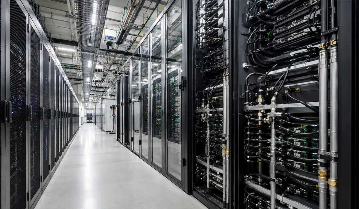
An AI data centre is a facility engineered specifically to support artificial intelligence workloads, and the busbar fabrication machine for AI data center has become the bottleneck that determines how quickly these facilities scale — primarily large-scale GPU-based model training and inference at hyperscale. What is an AI data center power infrastructure, and how does it differ from cable-based systems? The distinction from conventional cloud computing facilities is not semantic. It is structural. A standard cloud-era data centre rack draws 5–15 kW across a mix of general-purpose compute, storage, and networking. An AI data centre rack running systems like the NVIDIA GB200 NVL72 or GB300 draws 60–100 kW routinely, with cutting-edge configurations exceeding 200 kW in single racks. The power density difference is not marginal — it is categorical.
That shift changes everything downstream. At conventional rack densities, multiple 800-ampere cable runs can physically accommodate the current. At AI densities, that approach collapses. A single 100 kW rack at 54 volt distribution requires approximately 1,850 amperes of continuous current. Achieving that through parallel cable runs requires so many individual conductors that the overhead cable tray system becomes the limiting factor for facility expansion. Riser shafts cannot accommodate the cable volume. Cooling becomes impossible because the cable mass generates heat that the facility’s air-handling systems cannot dissipate. The engineering becomes untenable.
Further exploration of Busbar processing machine can be found in the following recommended reading.
A specialized busbar machine for data center environments produces the solution. Fabricated copper or aluminium busbars handle up to 6,300 amperes in a single run — delivering the current density required by AI infrastructure in a rigid, thermally superior, and installation-efficient form factor.
For a clearer comparison, you can review the information provided on this website about Technical documentation of next-generation AI infrastructure power architecture.
How AI Workloads Rewrite the Rules of Electrical Distribution
The physics of current flow creates an unavoidable constraint: when current increases, resistance losses grow as the square of the current. The formula is simple — P = I²R — and its consequences are absolute. Doubling the current quadruples the heat generation in a conductor. In a cable system serving a 100 kW AI rack, the resistive losses alone can reach 2–3 kW — heat that must be removed by the cooling system, which itself must then be oversized to handle that added thermal load. On a distributed busbar system — where rigid geometry minimizes connection resistance and multi-point contact reduces the current path losses — the same infrastructure dissipates perhaps 0.5 kW. That 2.5 kW difference compounds across dozens of racks and becomes a material difference in facility-wide cooling efficiency and operating cost.
Fabricated rigid busbars are not preferable to cables in high-current environments. They are technically mandatory. Cable systems cannot solve the thermal and space constraints at AI power densities. That is not marketing positioning — that is engineering fact.
You can check this page for more examples, explanations, and related technical resources on Engineering analysis of high-current power distribution requirements.
What Is a Busbar Fabrication Machine? Core Functions Explained
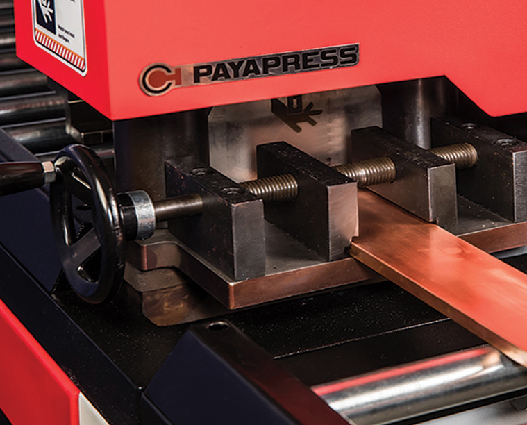
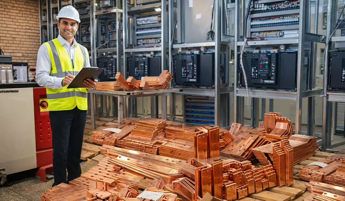
Understanding a CNC busbar machine for AI data center means recognizing it as a computer-numerically-controlled system that performs punching, shearing, and bending operations on copper or aluminium conductor bars, converting raw stock into dimensional precise components ready for electrical installation. In AI data centre supply chains, these machines are the production bottleneck that determines how fast new power infrastructure can be built and how consistently it performs.
A raw copper bar enters the machine as an unprocessed conductor. It exits as a finished busbar component — cut to exact length, punched with mounting holes in precise locations, shaped through bends and twists to match the facility’s installation geometry, and ready for bolted connection into the power distribution system. The three operations — punching, shearing, and bending — each serve a specific functional requirement.
For a comprehensive understanding of Electrical Bar Forming Equipment, we highly recommend reviewing this article.
Punching creates mounting holes, oblong slots, and custom cutouts in the conductor bar. CNC punching units use turret-style die sets to switch between hole geometries without manual tooling changes. In data centre applications, hole pattern accuracy directly affects contact resistance at bolted connections; dimensional variation introduces micro-gaps that increase resistance and heat generation over time.
Shearing cuts the bar to length with a clean, burr-free face. The cut face quality matters because any surface irregularity at a bolted joint creates thermal stress points during fault-current events. High-quality shear units produce faces that require no secondary finishing — the bar leaves the machine ready for immediate assembly.
Bending forms the bar into the three-dimensional geometry required by the installation — flat bends for horizontal busway sections, vertical bends for connection risers, edge bends for tight-space routing, and twist configurations for power factor correction applications. Bending accuracy determines whether the finished busbar fits the switchgear enclosure or busway section without mechanical stress at connection points.
Visit this page to learn more about the specifications, applications, and related details about Technical overview of CNC busbar processing systems.
CNC vs. Semi-Automatic vs. Portable: Choosing the Right Machine Class for Data Centre Production
The machine class decision is a real procurement question with material consequences. Full CNC systems deliver automation and precision. Semi-automatic machines offer cost savings. Portable hydraulic units provide field flexibility. Which class is correct depends on the production volume and tolerance requirements of the specific data centre supply contract.
| Machine Type | Automation Level | Max Busbar Size | Processing Speed | Best Fit for Data Centre Work |
|---|---|---|---|---|
| Full CNC (3-in-1) | Fully automatic | Up to 160 × 15 mm | Up to 75 m/min | High-volume hyperscale production |
| Semi-Automatic | Partial operator intervention | Up to 120 × 12 mm | Moderate | Mid-size contractor shops |
| Portable / Hydraulic | Manual-assist | Up to 80 × 10 mm | Low | On-site field modification only |
For an AI data centre supply contract, full CNC is the only rational choice. Here is why: AI facility buildouts operate on compressed schedules — the market window for capturing colocation revenue is measured in weeks, not months. Semi-automatic machines require operator intervention at each station, creating sequential processing bottlenecks that compound across large production runs. A machine down for die changes, programme adjustments, or maintenance becomes an unaffordable delay. Full CNC systems allow multiple operators to work punching, shearing, and bending stations concurrently, and software updates can be pushed to the machine remotely without stopping production. For production volumes above 500 custom busbar components per facility buildout, the full CNC machine eliminates the cost difference within the first contract through labour savings alone.
If we want to introduce a suitable device at an economical price in global markets, we can mention the HBC-EA120 machine.
Busbar Specifications That Actually Matter in AI Data Centre Environments
This section is where generic spec lists end and engineering begins. Each specification below is connected to a real consequence in an AI data centre environment. If the spec is wrong, something fails. If something fails, the data centre misses revenue targets. Be precise about why these specs matter.
Current Rating, Cross-Section, and Conductor Material
High current busbar AI infrastructure systems can deliver up to 6,300 amperes in a single run — far exceeding the 800–1,000 ampere practical limit of parallel cable systems. That capability is grounded in the electrical properties of the conductor material itself. Copper conductivity is approximately 58 megasiemens per metre; aluminium is approximately 35 megasiemens per metre. The busbar current rating data center engineers specify depends on conductor material choice than aluminium.
To better understand how to choose the right aluminum for busbars used in your data center, we recommend that you don’t miss reading this article.
This is not an academic distinction. For AI racks above 60 kW, copper is the engineering-correct choice. Aluminium is a cost trade-off that comes with real performance penalties at high current densities. When current increases, so does the temperature rise in the conductor. Aluminium’s lower thermal conductivity means higher equilibrium temperatures at equivalent current. Over 10 years of continuous operation, an aluminium busbar running at its maximum rated current experiences accelerated annealing — a loss of mechanical strength and increased brittleness at joint areas. Copper avoids that degradation. Additionally, aluminium requires anti-oxidant compound at all bolted connections; copper joints are inherently stable without additives.
For mission-critical AI infrastructure, the engineering case for copper is unambiguous.
| Property | Copper Busbar | Aluminium Busbar |
|---|---|---|
| Electrical Conductivity | ~58 MS/m (higher) | ~35 MS/m (lower) |
| Current per mm² (approx.) | Higher ampacity | ~35% lower ampacity |
| Weight | Heavier | ~30% lighter |
| Material Cost | Higher | Lower |
| Thermal Performance | Excellent | Good (derate at high load) |
| Joint Reliability | High (no additives required) | Requires anti-oxidant grease |
| Correct Use Case | AI racks >60 kW | Cost-sensitive, lower density |
Real-World Case Study: Busbar Fabrication for a Hyperscale AI Data Centre Retrofit
A North American colocation operator in 2025 began retrofitting using a purpose-built busbar fabrication machine for AI data center to solve a scaling problem three existing data centre halls to support GPU-dense AI tenants. The existing infrastructure used cable-based distribution designed for 8–12 kW per rack. New tenant requirements called for 80–100 kW per rack.
The situation. The cable tray systems in the existing halls had no remaining capacity. Adding parallel cable runs for the required current would have required ripping out and rebuilding the entire overhead cable pathway infrastructure — a project estimated at 14 weeks per hall and approximately $2.8 million per facility. More critically, the overhead space available in the raised-floor facility simply could not accommodate the cable volume required for 100 kW racks at any price. The facility’s engineering team was facing a choice between capital expenditure that would cripple facility economics or refusing to upgrade and watching tenants move to purpose-built AI facilities.
The engineering decision. The facility’s electrical contractor specified a modular overhead busbar trunking system AI data center deployment busbar trunking system for the new AI zones. Copper busbars were fabricated using a full CNC 3-in-1 processing machine, producing consistent cross-section geometry across a large batch of custom-length sections. Because CNC fabrication supports DXF and 3D CAD drawing import, the entire busbar set for the first hall was programmed from the building’s electrical drawings and produced in two production shifts. The modular tap-off design allowed the contractor to specify different busbar cross-sections for different zones, optimizing conductor size to actual load rather than over-sizing for the worst-case rack configuration.
What the numbers showed. Installation time for the busbar system was approximately 40–50% faster than the cable alternative would have been — consistent with industry benchmarks reported from Data Centre World 2026. Because the modular tap-off system uses standardised connection geometry, rework and field adaptation were minimal. The operator was able to reuse the existing overhead structural pathway for the busbar mounting, avoiding the full infrastructure rebuild. Within six months of the retrofit, the first hall was supporting 24 GPU-dense AI racks where the original infrastructure could only support 3 cable-based 12 kW racks. The busbar system paid for itself through incremental tenant revenue within the first year of operation.
Reference: IoT Analytics — Data Centre Trends 2026 — Industry analysis of hyperscale infrastructure adaptation.
Busbar vs. Traditional Cable Distribution: A Decision-Maker’s Comparison
The busbar vs cable distribution AI data center choice is now clear: in standard data centre environments. In AI data centre environments — where rack densities routinely exceed 60 kW — it is not close. The data supports a clear conclusion: approximately 70% of new data centre projects in 2026 are specifying busbars over cables in the grey space. That is not a trend. It is a market-wide acknowledgment that the old architecture does not work.
| Criteria | Busbar Fabrication System | Traditional Cable Distribution |
|---|---|---|
| Current Capacity | Up to 6,300A in a single run | Requires multiple parallel cables >800A |
| Physical Footprint | 60–70% less space | Bulky trays and conduit systems |
| Installation Speed | 40–50% faster (modular sections) | Labour-intensive; slow termination work |
| Energy Efficiency | Up to 99% | 95–97%; losses increase at joints |
| Thermal Performance | Superior; lower operating temperature | Higher temperatures; derating required |
| Fault Current Withstand | Rigid; mechanically braced | Flexible; risk of violent movement |
| Scalability | Tap-off units; no cable reruns | Full cable reruns for changes |
| Maintenance Access | Visible; inspection-friendly | Hidden terminations; difficult access |
| Initial Material Cost | Higher | Lower |
| 3–5 Year ROI | Positive (energy + labour savings) | Higher total lifecycle cost |
Busbars deliver superior performance across every material criterion except initial purchase price. At AI rack densities, the higher initial material cost is offset by faster installation (lower labour cost), lower ongoing energy losses, and the avoided cost of rework when rack configurations change. A system that requires a full cable rerun every time a tenant changes rack layout is not fit for the dynamic operating model of a modern AI colocation facility.
How to Select a Busbar Fabrication Machine for AI Data Centre Production
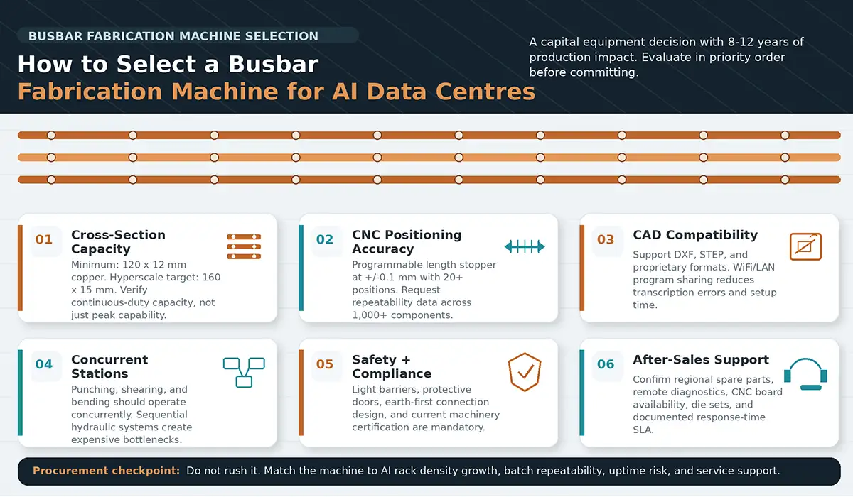
How to choose busbar fabrication machine AI data center requires evaluating against these criteria. The procurement decision for a busbar fabrication machine for AI data center is a capital equipment decision with consequences that extend 8–12 years. Do not rush it. Evaluate against the following criteria, in order of importance.
Maximum cross-section handling. For AI data centre supply contracts, the machine must handle at least 120 × 12 mm copper. True hyperscale work requires 160 × 15 mm capacity. Machines limited to smaller cross-sections will become a production constraint within 24 months as AI rack densities continue to increase and tooling requirements scale upward. Verify maximum cross-section under continuous duty, not just peak capability.
Positioning accuracy and length stopper. Busbar machine tolerances for high-density AI server racks require CNC machines with programmable length stoppers at ±0.1 mm tolerance, programmable to 20+ positions) are non-negotiable. Manual positioning introduces variation that compounds across large batch runs — unacceptable for safety-critical infrastructure. Request dimensional repeatability data across a batch of 1,000+ components, not just accuracy on a single sample.
Software and drawing compatibility. The machine must support 2D/3D CAD drawing import via DXF, STEP, and proprietary formats. WiFi/LAN connectivity for real-time program sharing between punching and bending stations eliminates transcription errors and cuts setup time on complex custom profiles. For AI data centre projects where design changes occur mid-production, this software integration is operationally critical.
Simultaneous multi-station operation. High-volume data centre production requires machines where punching, shearing, and bending stations can be operated concurrently by separate operators. Machines with shared hydraulic systems that allow only sequential operations create production bottlenecks that make high-volume contracts unprofitable.
Safety systems and compliance. Light barriers, protective doors, and earth-first connection design are mandatory — not optional. Any machine specified for professional production environments must hold current machinery safety certification (CE marked in Europe, equivalent in North America).
After-sales infrastructure. Hydraulic power pack components, die sets, and CNC control boards have lead times. Before committing to a machine, verify that spare parts are stocked regionally (not ordered on demand from Asia), that the manufacturer provides remote diagnostics support, and that there is a documented response time SLA. A machine down during a data centre buildout window is an extremely expensive failure.
The Fabrication Workflow: From Raw Copper Stock to Data Centre-Ready Busbar
The production run begins when the busbar drawing — typically exported from the facility’s CAD package as a DXF file — is imported into the CNC machine’s control system via USB or LAN. Modern machines receive live programme updates from the engineering team while the machine is running, operationally critical when design changes occur mid-production on a fast-moving data centre project.
In a copper busbar processing machine, copper or aluminium bar stock is selected to the specified cross-section and loaded into the machine’s feeding system, which positions it to the first cut coordinate using the programmable length stopper. The operator verifies material alignment and initiates the automated sequence.
The shearing unit makes the first cut. On a high-quality machine, the cut face is flat, perpendicular, and free of burrs without secondary operations. The punching unit indexes through the programmed hole pattern. On machines with turret-style die changers, die selection is automatic. For standard data centre busbar profiles, hole patterns typically include M8 and M10 mounting holes plus oblong slots for thermal expansion accommodation.
A copper busbar bending machine at hyperscale data center scale forms the bar to the three-dimensional geometry required by installation. For overhead busway sections, this is typically a series of flat bends. For connection tails entering switchgear, edge bends and twist geometries are common. CNC bending with programmed angle control eliminates trial-and-error adjustment cycles.
After machining, exposed connection areas are insulated using heat shrink tubing rated for the operating voltage. For data centre busbars, heat shrink tubes rated at 1 kV or higher with flame-retardant properties are standard. The tube is applied and shrunk with a heat gun or oven, creating a conforming insulation layer without air gaps.
The finished busbar is measured against the drawing using a coordinate template or CMM check. Critical dimensions — hole centres, bend angles, overall length — are verified before labelling, packaging, and release to the installation team.
If the information related to Raw Copper Stock to Data Centre-Ready Busbar was interesting and informative to you, researching Busbar Manufacturing Process can be very engaging.
Future of Busbar Fabrication in the AI Infrastructure Era
Reference: IndexBox — Plug-in Busbar Systems Market Analysis — Market projection data through 2035.
The evolution of busbar fabrication is being driven by four concrete developments in AI infrastructure architecture.
NVIDIA’s 800 VDC in-rack distribution architecture is designed to reduce conductor mass at hyperscale, but higher voltage raises the bar for fabrication precision. Tighter insulation clearances, higher-grade dielectric materials, and more precise connection geometry are required at 800 V than at 54 V. Machines capable of ±0.05 mm positioning tolerances and automated insulation application will differentiate suppliers in the next cycle.
Modern CNC busbar machines are increasingly connected to industrial IoT platforms, enabling real-time production management systems that monitor output rates, die wear, and machine health. For manufacturers supplying data centre projects at scale, this connectivity enables predictive maintenance scheduling that prevents unplanned downtime during critical production windows. The sophistication of busbar fabrication equipment for hyperscale AI facility buildouts continues to increase as production volumes scale.
The global plug-in busbar market is projected to reach an index of 195 by 2035 (2025 = 100), representing compound annual growth driven by the structural demand shift as AI workloads replace general-purpose cloud computing as the dominant data centre use case. In raw material terms, that growth translates to approximately 3.5 million tonnes of fabricated busbar per year by 2035 — a production volume that will require significant manufacturing capacity investment globally.
Conclusion Busbars system in the AI Infrastructure
The busbar fabrication machine is no longer a commodity production tool. It is the industrial equipment that enables AI data centre infrastructure to scale beyond the physical limits of cable-based systems. For data centre operators, electrical contractors, and infrastructure manufacturers evaluating production equipment, the evaluation criteria are clear: maximum cross-section handling, positioning precision, software integration, and regional after-sales support. For procurement teams specifying components, the choice is equally clear: copper busbars, full CNC fabrication, and documented compliance certification are not optional for mission-critical facilities.