









Prefer listening? You can play the audio version of the rest of this article below.
What Is a DIN Rail and Why Does It Matter in Control Panels?
A DIN rail is a standardized metal strip that secures electrical components inside an enclosure. The name originates from (Deutsches Institut für Normung), the German standards body that first published the specification.
Today, IEC 60715 governs rail dimensions worldwide. As a result, parts from different manufacturers fit any compliant top hat rail. This interoperability lies at the heart of why DIN Rail in Control Panels became the global default.
Standardization eliminates guesswork. Instead of drilling custom holes for every relay or breaker, technicians simply snap components onto the symmetrical DIN rail. Consequently, build times shrink, errors drop, and maintenance teams replace parts faster.
In modern cabinets, terminal blocks, miniature circuit breakers, contactors, PLCs, and surge protectors all mount on a hat rail. Moreover, the rail itself often doubles as a grounding reference when properly bonded to earth.
Without this modular rail system, large-scale industrial automation would be slower, costlier, and far less flexible than it is today.
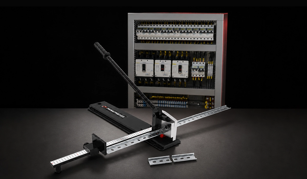
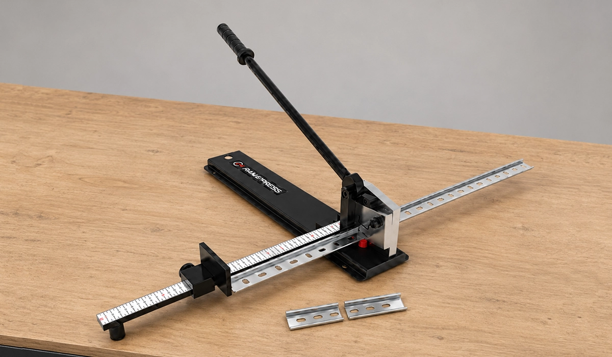
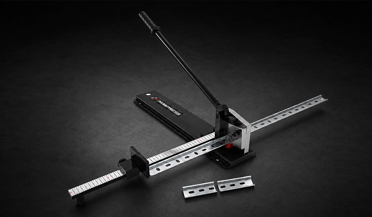
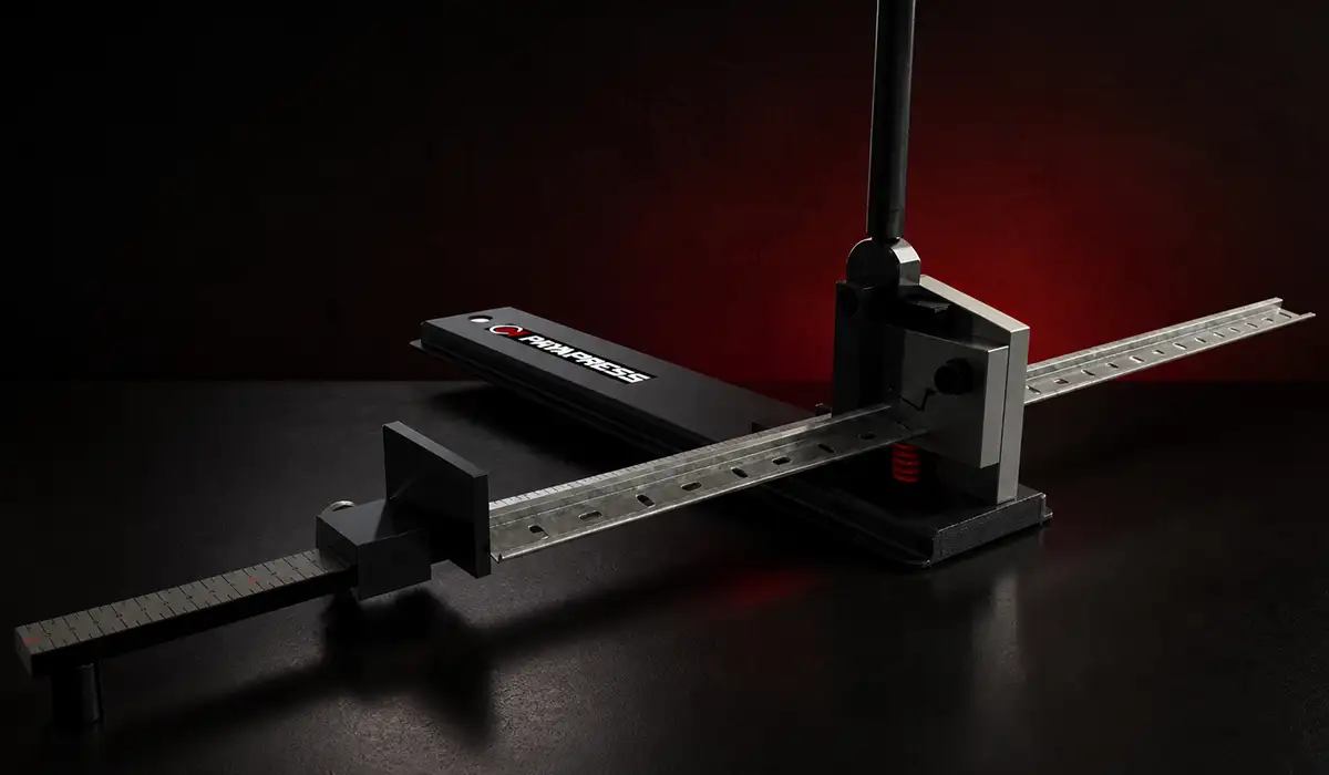
For example, one of the most reliable and practical products on the market is the DIN rail cutter from PAYAPRESS Company, which can significantly address your requirements for this application.
Types of DIN Rail Used in Control Panels
DIN rail types for control panels fall into several distinct profiles. Each profile suits a particular component family, mechanical load, or enclosure size. Selecting the right rail upfront prevents costly redesigns later.
The most common option is the top-hat rail in either TS 35 or TS 15 width. G-type and C-section profiles serve heavier or legacy applications. Furthermore, perforated and solid variants offer trade-offs between weight, ventilation, and rigidity.
The table below compares the main rail profiles you will encounter when sourcing the best DIN rail for industrial control panels.
| Rail Type | Profile | Width | Common Use |
|---|---|---|---|
| Top Hat Rail (TS 35) | Symmetrical Ω-shape | 35 mm | Most common; terminal blocks, MCBs, relays |
| Top Hat Rail (TS 15) | Symmetrical Ω-shape | 15 mm | Compact panels with limited space |
| G-Type Rail (G 32) | G-shaped profile | 32 mm | Heavy-duty components, older equipment |
| C-Section Rail | C-shaped channel | Various | Busbar systems, high-current applications |
| Perforated DIN Rail | TS 35 with holes | 35 mm | Easier grounding, ventilation, lower weight |
| Solid DIN Rail | TS 35 without holes | 35 mm | Maximum mechanical strength |
When in doubt, specify perforated TS 35 steel. It covers roughly 80% of typical industrial panel builds. However, always confirm component compatibility before ordering bulk lengths. Mixing rail profiles within one cabinet works but adds inventory complexity.
Each manufacturer designs around IEC 60715, which ensures cross-brand compatibility regardless of the supplier you choose. Therefore, panel builders can switch vendors without redesigning their mounting layout.
If you are looking for more information about DIN rail cutter reliable equipment options, it is recommended not to miss reading this article.
This downloadable guide gives you a more structured overview of the subject “Defines standardized rail dimensions for the mechanical support of electrical devices in switchgear and controlgear installations”.
TS 35 (35mm Top Hat Rail) — The Industry Standard
The TS 35 dominates the global market for one simple reason: nearly every modern electrical component fits it. From terminal blocks to MCBs, DIN-mount PLCs, and contactors, manufacturers default to the 35mm omega rail profile.
It complies fully with IEC 60715 and EN 50022. Therefore, you can mix brands freely across the same rail without compatibility concerns.
TS 15 (15mm Top Hat Rail) — For Compact Enclosures
The difference between 35mm and 15mm DIN rail comes down to space. TS 15 suits compact junction boxes, sub-panels, and lightweight signal terminal blocks where a full-size rail wastes precious depth.
However, TS 15 carries far fewer component options. Use it only when you have confirmed all required parts in the 15mm footprint.
You can find more background information and related technical notes through this reference link about Searchable repository of technical FAQs covering rail systems, terminal blocks, and panel components.
For a comprehensive understanding of DIN rail standards, we highly recommend reviewing this article.
G-Type and C-Section Rails — Specialty Applications
G-type rail and C-section rail handle niche cases. G 32 still appears in older switchgear and certain heavy fuse blocks. C-section profiles, meanwhile, support busbar-based component rail systems carrying high currents.
For most new designs, however, engineers should default to TS 35. Specify these specialty rails only when an existing installation or component demands it.
Materials and Finishes — Steel vs. Aluminum DIN Rails
The aluminum vs steel DIN rail for panels debate has clear answers once you understand the trade-offs. Each material suits a different operating environment, and choosing wrong leads to corrosion, sag, or thermal issues.
Steel is the default choice for industrial enclosures. It offers superior mechanical strength, holds heavy components without bending, and accepts zinc plating for corrosion protection. Most factory-floor panels use cold-rolled, zinc-plated steel.
Aluminum trades raw strength for lower weight and better corrosion resistance. Marine cabinets, food-processing lines, and weight-sensitive outdoor enclosures often specify aluminum. Furthermore, aluminum conducts heat and electricity well, which can simplify grounding strategies.
| Property | Steel | Aluminum |
|---|---|---|
| Mechanical strength | Excellent | Moderate |
| Corrosion resistance | Good (with plating) | Excellent |
| Weight | Heavier | ~35% lighter |
| Conductivity | Lower | Higher |
| Cost | Lower | Higher |
Surface finish matters as much as base material. Beyond raw steel or aluminum, consider zinc plating, chromate conversion coatings, or stainless steel for harsh environments. Each adds cost but extends rail life significantly.
When in doubt, choose zinc-plated steel. It performs reliably in 90% of industrial DIN rail systems and remains the most economical option for high-volume cabinet builds.
To choose the right solution, learn about the types of DIN rail and their specifications.
IEC and UL Standards Governing DIN Rails in Control Panels
Standards compliance is not optional in professional panel building. Three documents shape how engineers must specify, install, and certify DIN Rail in Control Panels.
IEC 60715 governs DIN rail dimensions globally. It defines the precise width, depth, and tolerance of every recognized profile. Therefore, components from compliant manufacturers always fit a compliant rail.
UL 508A regulates control panel construction in North America. It addresses everything from wire sizing and short-circuit current ratings to rail-mounted device spacing and labeling. Panels destined for the US market typically require UL 508A listing.
EN 50022, meanwhile, is the European equivalent covering TS 35 and TS 15 profiles. It aligns closely with IEC 60715 and remains in widespread use across the EU.
Failure to comply creates real consequences. Inspectors can reject panels, insurers can void coverage, and end-users may face liability after incidents. Consequently, panel builders should always document which standards apply to each project before cutting the first rail.
For offline reading, you can download the complete document from this link.
How to Install DIN Rail in a Control Panel — Step by Step
Knowing how to install DIN rail in electrical control panel work properly separates clean, maintainable cabinets from messy ones. The procedure below follows industry best practices used by professional integrators worldwide.
Plan the layout before cutting anything. Map every component, leave room for wire ducts, and respect minimum spacing between rails — typically 100 mm or more for thermal management and access.
Follow these steps in order:
- Measure the available enclosure space and plan rail positions.
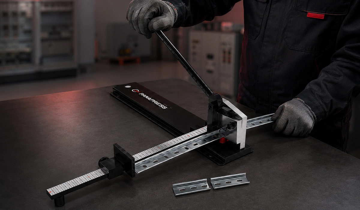
- Cut the rail to length using a hacksaw or dedicated rail cutter.
- Deburr cut edges so wires and fingers stay safe.
- Mark and drill mounting holes every 100–200 mm.
- Secure the rail with appropriate screws and end clamps.
- Verify the rail is level and mechanically stable.
- Bond the rail to ground if it serves as an equipotential reference.
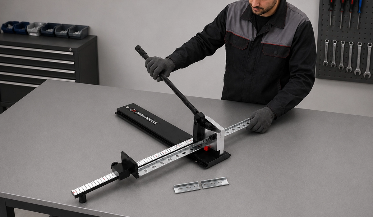
Tools matter too. A quality rail cutter beats a hacksaw for clean ends, while a torque-controlled screwdriver protects the rail from over-tightened mounting screws.
Following this sequence prevents the most common installation defects, including rail slippage, component sag, and improper grounding paths. Furthermore, a clean install simplifies future troubleshooting and panel expansion.
Cutting and Sizing DIN Rail Correctly
How to cut and mount DIN rail in enclosure work starts with accurate measurement. Always account for end brackets, stop plates, and a small expansion buffer when calculating rail length.
Use a fine-tooth hacksaw or a dedicated rail cutter for clean, square cuts. Furthermore, deburr every edge. Sharp edges damage wire insulation and injure technicians during maintenance.
Grounding the DIN Rail — Why It’s Not Optional
Grounding DIN rail in electrical panel work creates a common equipotential surface that protects people and equipment. A bonded rail ensures any fault current finds a low-impedance path to earth.
Use ground bus bars or dedicated grounding clips designed for TS 35. Confirm continuity with a low-resistance ohmmeter after installation. Skipping this step violates NFPA 79 and IEC 60364.
Download the complete reference material to support your planning, analysis, or procurement process about Authoritative grounding and bonding requirements for industrial machinery and control system enclosures.
DIN Rail Accessories Every Panel Builder Should Know
The right DIN rail accessories for control panel building turn a basic rail into a complete mounting system. Forgetting even one item often forces a return trip to the supplier mid-build.
Stock these essentials for every cabinet project:
- End brackets / end stops — prevent component slippage along the rail.
- Rail couplers — extend rail length without seams.
- Grounding clips and ground bus bars — provide safe earth bonding.
- DIN rail labels and marking systems — improve traceability.
- Mounting feet and insulating feet — adapt rails to non-standard surfaces.
- Section dividers — separate signal and power zones for EMC.
Each item costs little but prevents real headaches. Furthermore, standardizing accessories across projects simplifies inventory and speeds future builds. Keep a small kit of common parts in every panel-build workshop.
Smart Control panel DIN rail components selection extends beyond the rail itself. Many builders overlook section dividers and insulating feet. However, these unsung parts solve real problems — preventing accidental contact between adjacent component groups and isolating the rail from ungrounded surfaces.
DIN Rail Load Capacity and Component Spacing Best Practices
Effective DIN rail layout planning for control cabinets prevents two of the most common build failures: mechanical sag and thermal stress. Both stem from ignoring load and spacing limits.
Steel rails carry significantly more weight than aluminum. A standard zinc-plated TS 35 supports several kilograms per linear meter without measurable deflection. Aluminum rails sag sooner under heavy contactors or busbar assemblies.
Component spacing matters just as much as raw load. Power components — variable frequency drives, soft starters, large contactors — generate heat that must dissipate freely. Crowding them defeats convection cooling and shortens device life.
Apply the 80% fill rule as a professional benchmark. Leave at least 20% of every rail empty for future expansion, maintenance access, and airflow. Furthermore, never exceed manufacturer-stated spacing minimums between heat-producing components.
Overloading the rail seems harmless at install time. However, six months later, sagging rails pull screws loose and stress wire terminations. Planning capacity from day one avoids this entirely.
Common Mistakes When Using DIN Rail in Control Panels
Even experienced builders make recurring mistakes with DIN Rail in Control Panels. The five errors below appear most often in audits and field failures.
Improper rail grounding. Floating rails create unpredictable fault paths. Always bond the rail to protective earth, even when components carry their own ground terminals.
Undersized rail for heavy components. Aluminum rail under a large contactor sags within weeks. Match material strength to component mass and vibration profile.
Ignoring spacing requirements. Packing the rail to maximum density looks efficient but kills thermal performance. Maintain manufacturer-specified clearances between drives, breakers, and other heat sources.
Skipping end brackets. Without end stops, components slide along the rail under vibration. They eventually short, disconnect, or damage adjacent devices.
Mixing incompatible footprints. Some legacy components use non-standard profiles. Confirm every part matches the rail standard before installation. Cross-checking saves hours of rework.
Avoiding these five mistakes alone improves panel reliability and audit pass rates dramatically.
Conclusion about DIN Rail in Control Panels
DIN Rail in Control Panels remains one of the most quietly important innovations in industrial electrical design. From the original German specification to the global IEC 60715 standard, the humble mounting strip enables interchangeability, faster builds, and safer panels.
Choosing the right rail type, material, and accessories takes minutes once you know what to look for. Following installation best practices — careful cutting, proper grounding, and disciplined spacing — extends the life of every cabinet you build.
Whether you specify panels for a single machine or oversee fleet-wide rollouts, the principles in this guide help you avoid costly mistakes. Furthermore, sticking to recognized standards protects your projects from inspection failures and warranty disputes. Treat the rail not as an afterthought but as the structural and electrical foundation of every control panel you produce.
FAQs about DIN Rail in Control Panels


Rate this article
Choose a rating from 1 to 5 stars.
No ratings yet