









Prefer listening? You can play the audio version of the rest of this article below.
What Is TS35 DIN Rail?
TS35 DIN rail is a standardized metal mounting rail used inside electrical enclosures and control panels. It is also called top hat rail, omega rail, or 35mm DIN rail because its cross-section looks like a raised hat or Ω-shaped form.
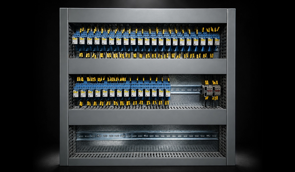
In practice, TS35 DIN rail gives panel builders a common mechanical interface. Circuit breakers, terminal blocks, relays, power supplies, timers, and PLC modules clip onto the same rail without custom brackets.
The “TS” designation means top hat symmetrical. This symmetry matters because the raised central channel and outward-facing flanges allow spring-clip devices to snap on and off with minimal tool use.
Therefore, the TS35 DIN rail profile turns enclosure assembly from custom fitting into repeatable panel shop work. IEC 60715 governs the standardized rail profiles used for compatible mounting.
TS35 Rail Dimensions and Geometry — The Exact Specifications
TS35 rail dimensions matter because interchangeability depends on them. The 35mm DIN rail standard lets components from different manufacturers fit the same electrical enclosure rail without special adapters.
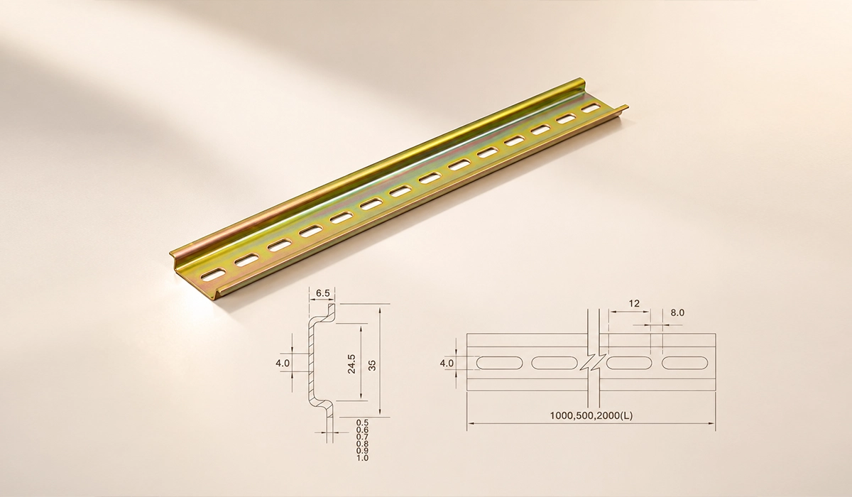
For readers checking TS35 DIN rail dimensions and specifications, the key values are width, height, flange geometry, thickness, hole pattern, and standard length. Small errors in any of these values can lead to loose mounting or difficulty removing.
| Dimension | Specification |
|---|---|
| Overall Width | 35 mm |
| Overall Height | 7.5 mm (standard) / 15 mm (deep profile) |
| Flange Width | 27 mm between inner flange edges |
| Rail Thickness | Typically 1.0 mm (aluminum) / 1.5 mm (steel) |
| Slot Hole Spacing | 25 mm centers on standard perforated rail |
| Standard Lengths | 1 m, 2 m; cut to length on site |
| Governing Standard | IEC 60715 / DIN EN 60715 |
The 7.5 mm version suits most DIN rail panel building work. However, the 15 mm deep version gives more clearance behind the rail.
As a result, designers often choose the deeper profile when grounding conductors, rear clearance, or heavier components need more space under the mounting surface.
For a clearer comparison, you can review the information provided on this website about width, depth, hole size, and 25 mm spacing data.
Material Options for TS35 Rails
TS35 rails usually come in zinc-plated mild steel, stainless steel, or aluminum. Each material changes corrosion behavior, weight, cutting effort, grounding performance, and long-term enclosure reliability.
When buyers compare TS35 DIN rail aluminum vs steel, they should start with the application environment. A clean indoor cabinet needs a different rail than a washdown panel, outdoor box, or lightweight machine enclosure.
| Material | Corrosion Resistance | Weight | Cutting Ease | Typical Application |
|---|---|---|---|---|
| Mild Steel, Zinc-Plated | Moderate | Heavy | Moderate | Standard indoor enclosures |
| Stainless Steel | Excellent | Heavy | Difficult | Food processing, washdown areas, outdoor installations |
| Aluminum, Anodized | Good | Light | Easy | Lightweight panels, corrosive environments |
Zinc-plated mild steel remains the default choice for most indoor panel builds. It offers good stiffness, wide availability, predictable clip retention, and suitable conductivity for many grounding arrangements.
However, stainless steel earns its place in harsh environments, while aluminum is better suited when weight and corrosion resistance matter more than maximum rail stiffness. Therefore, material choice should follow load, atmosphere, and bonding needs.
This reference page is useful for readers who want to study the topic of lists of rail materials, coatings, and profile variants beyond this article.
Why TS35 Became the Global Standard
The answer to why TS35 is the standard DIN rail profile starts with standardization. DIN rail concepts originated in German industrial standardization, and later gained broader European and international alignment through EN and IEC standards.
Next, the top hat rail profile solved real engineering problems. Its geometry gives good rigidity relative to material weight, while its flanges create a repeatable snap-on interface for terminal blocks, breakers, relays, and control modules.
The standard then gained a network effect. Once Phoenix Contact terminal systems, Weidmüller rail components, Schneider Electric panel systems, Siemens SIMATIC components, ABB industrial components, and Eaton electrical components supported TS35, the standard reinforced itself.
As a result, the most common DIN rail type did not win by marketing alone. It won because component makers, enclosure manufacturers, and panel builders all gained time, compatibility, and lower layout risk from one shared rail geometry.
For readers who want more technical depth, this reference page is a useful starting point.
What Components Mount on TS35 Rail?
Many rail-mounted components use TS35 top hat rail as their default mechanical interface. In practical terms, what TS35 DIN rail is used for usually means mounting control, protection, connection, and measurement devices.
Components commonly mounted on TS35 rail include:
- Miniature circuit breakers and residual current devices
- Terminal blocks, including feed-through, PE, fused, and disconnect types
- Relays and relay sockets
- Solid state relays and compact contactors
- Power supplies and DC-DC converters
- PLCs and remote I/O modules
- Motor protection switches
- Surge protection devices
- Energy meters and current transformers
- Time relays, counters, and signal conditioners
For many panel builders, TS35 DIN rail for circuit breakers and terminal blocks defines the basic layout of an enclosure. Protection devices often sit in one zone, while terminal block mounting rail groups field wiring nearby.
Therefore, the snap-fit mechanism cuts assembly time. Installers can add, remove, or reposition most devices without drilling new holes in the back panel.
To explore the topic in greater depth, review the information available on this website.
TS35 vs Other DIN Rail Profiles — Understanding the Differences
TS35 dominates new electrical panel construction, but other rail profiles still appear in legacy cabinets, compact instrumentation, and some older component families. Therefore, designers must know the difference between TS35 and TS32 DIN rail before retrofit work.
| Rail Type | Width | Profile Shape | Key Difference from TS35 | Typical Use Case |
|---|---|---|---|---|
| TS35, 7.5 mm | 35 mm | Top Hat / Omega | Industry standard | Universal modern panel builds |
| TS35, 15 mm | 35 mm | Top Hat / Omega | Deeper profile for increased rigidity and grounding clearance | High-current or grounding-intensive panels |
| TS32 | 32 mm | Symmetric C | Older, narrower standard | Legacy European installations |
| G-Rail (G32) | 32 mm | G-Shaped | Open profile with no top flange | Older contactors and heavy-duty components |
| Miniature Rail | 15 mm | Top Hat | Narrower, designed for lighter-duty applications | Compact enclosures and instrumentation panels |
For new panel work, specify TS35 at 7.5 mm unless the component datasheet, grounding plan, or load condition demands another profile. Retrofitting mixed rail types usually adds complexity.
In contrast, legacy TS32 or G32 rails can force adapter use, component substitution, or layout changes. Consequently, procurement teams should verify rail type before ordering replacement devices.
You can explore this trusted source for more complete and updated information on Compares common 35 mm rail heights and mounting uses.
Perforated vs Unperforated TS35 Rail — Which Should You Specify?
Perforated TS35 rail has slotted holes, often on 25 mm centers, which simplify fixing to an enclosure back panel. Installers can position screws or bolts at convenient points along the rail length, so perforated rail suits most enclosure mounting systems.
However, those holes remove some metal. The reduction usually does not matter in normal control panel fabrication, but heavy devices, vibration, or long unsupported spans may justify a solid rail.
Unperforated TS35 rail offers higher rigidity because it keeps the full metal section intact. It works well when the rail clamps at its ends, carries heavier components, or needs custom holes drilled only where required.
Therefore, choose perforated rail as the standard for most panel shop work. Choose unperforated rail only when the load, fixing method, or enclosure design gives a clear structural reason.
For readers who want more technical depth, this reference page is a useful starting point.
You can explore this trusted source for more complete and updated information on Compares common 35 mm rail heights and mounting uses.
Installing TS35 Rails — Key Practical Considerations
Correct rail installation affects wiring space, service access, component cooling, and future modification work. Therefore, plan rail positions before cutting any stock length.
A clean installation sequence also reduces burrs, misalignment, and rework. For teams asking how to mount components on TS35 DIN rail, the rail itself must first sit square, flush, and securely bonded where required.
- Measure and mark rail positions on the enclosure back panel.
- Account for component height, cable ducts, bending radius, and service access.
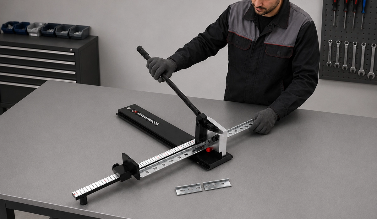
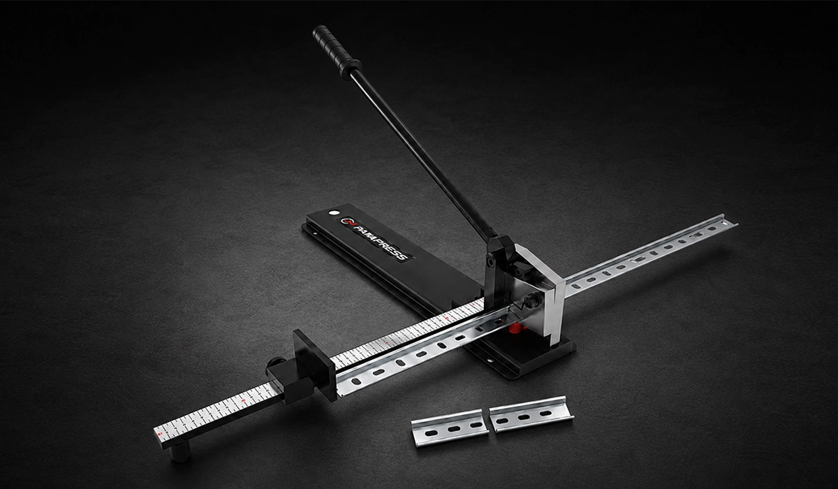
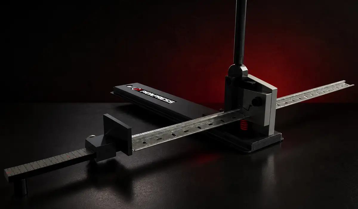
- Cut rail to length with a DIN rail cutter or hacksaw and miter guide.
- Deburr both cut ends before handling or fitting.
- Position the rail and mark fixing holes through the perforations.
- Drill and tap the panel, or use approved self-tapping mounting screws.
- Secure the rail with suitable fasteners; M4 screws suit many TS35 applications.
- Check that the rail sits flush and square before loading components.
- Install a grounding conductor under or near the rail if the design requires it.
As a result, early layout decisions determine how much working space remains for wiring and maintenance. Good rail placement saves far more time than it costs.
Grounding and Bonding Considerations for TS35 Rail
In many panels, the rail can form part of the protective earth path. PE terminal blocks may contact the rail directly, and the rail then bonds to the enclosure earth point through a suitable conductor or mounting system.
However, TS35 DIN rail grounding and bonding still need design control. Zinc-plated steel often gives suitable surface conductivity, while anodized aluminum may need special grounding clips or prepared contact areas.
For small control circuits, rail-based PE terminals can work well. In contrast, panels with high fault current, multiple incoming earth conductors, or strict customer specifications may require a separate copper ground bus bar.
The 15 mm deep profile can also help. It provides more space under the rail for grounding conductors, bonding straps, or routing clearance, especially in dense industrial control panels.
Conclusion TS35 standard
TS35 did not become the dominant rail profile by accident. It combines a practical symmetrical mounting rail, a stable 35 mm geometry, reliable snap-fit installation, and decades of manufacturer adoption.
Therefore, it remains the default choice for modern enclosure assembly, control panel fabrication, and panel wiring accessories worldwide. When designers choose the right height, material, perforation style, and grounding method, TS35 gives a simple mechanical standard with major gains in compatibility, serviceability, and assembly speed.


Rate this article
Choose a rating from 1 to 5 stars.
No ratings yet