






If you’d rather listen than read, feel free to play the audio file below for the rest of this article.
Why Aisle Width Is Set by the Breaker Truck
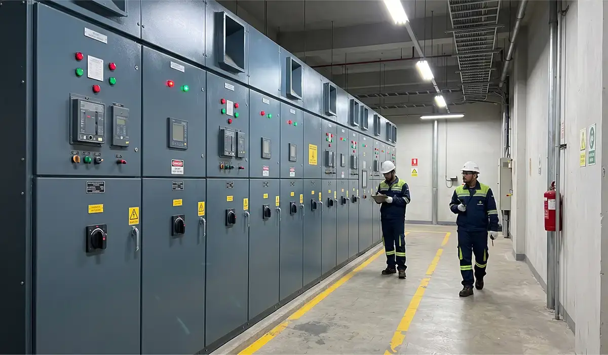
The front aisle is best explained as a picture. Start with the panel depth, then add the withdrawable truck pulled fully out onto its service trolley. Next, add room for a person and for turning the trolley.
That total is the switchgear withdrawal space, and it is much bigger than a walking aisle. Walking vs withdrawal is the key difference: one needs room for a body, the other for a breaker, a trolley and a person.
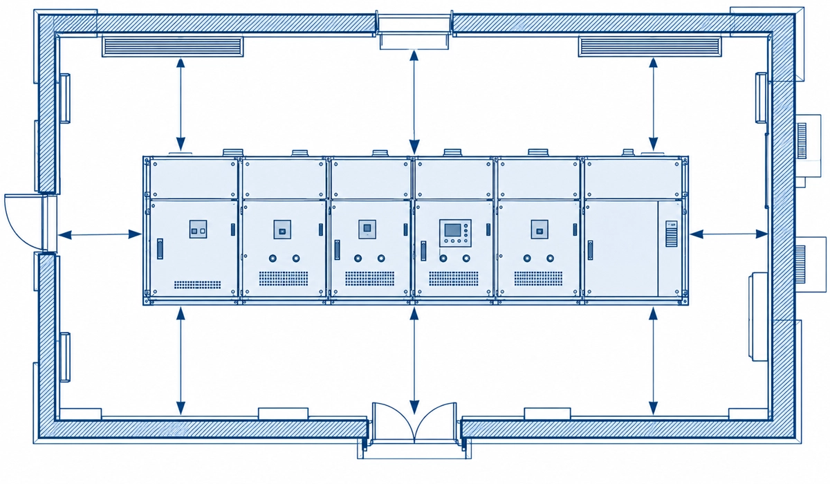
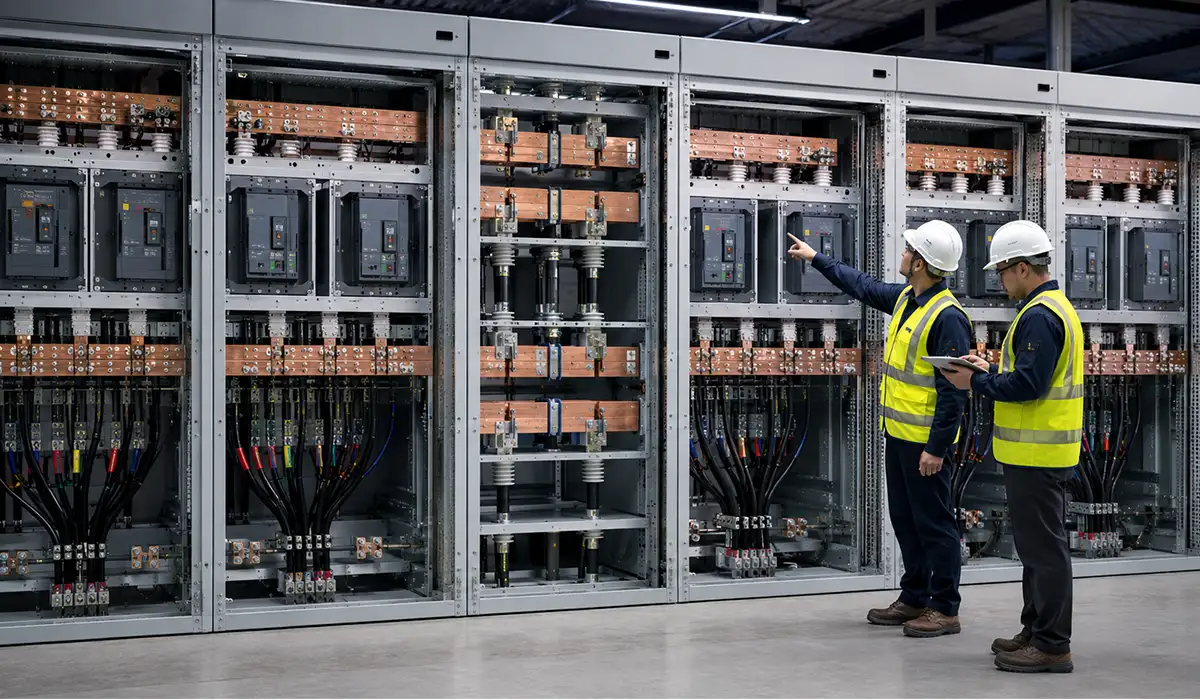
For a medium voltage switchgear room layout, draw a plan view early: the lineup, the front aisle with a truck on its trolley, the rear gap and two exits. It turns switchgear clearance requirements into a drawing everyone can check.
Room layout is only one part of a compliant installation. For the wider picture, read our guide to switchgear standards and how they apply to your project.
Front Aisle: The Operating and Withdrawal Space
Switchgear front clearance has two numbers that matter. The first is the minimum operating aisle the installation standard allows. The second is the withdrawal space the maker needs for its truck.
Always use the larger of the two. In most MV rooms, standard vs maker is not a close call, because the maker’s figure is bigger.
The international rules for these rooms sit in one installation standard for systems above 1 kV. The IEC describes the scope of the 2021 edition on its IEC 61936-1 page.
Minimum From the Standard
What is the minimum aisle width in a switchgear room under the standard? IEC 61936-1, which covers power installations above 1 kV AC, sets rules for aisles, access areas and escape routes. It requires operating aisles wide enough for safe operation and inspection, and it says that doors and open parts must not block an escape route.
The exact widths and conditions depend on the edition and its clauses. The 2014 amendment, for example, simplified the escape-route rules. Therefore, read the figures from the clause in the edition your project uses, rather than from a summary or an old drawing.
National codes may also add to it. Some countries, for instance, require access from both ends of long gangways.
Maker flyers publish this aisle as a fixed dimension, because it depends on their truck and trolley. One North American metal-clad switchgear flyer lists recommended and minimum drawout aisles in its drawout aisle table.
Real Need From the Maker’s Truck and Trolley
How much space is needed in front of MV switchgear? The maker answers that. Here is one example from an ANSI switchgear flyer (example — check your switchgear):
- Recommended drawout aisle: about 1,830 mm (72 in), which allows breakers to be interchanged.
- Minimum with a lifting truck: about 1,650 mm (65 in).
- Minimum with all breakers at floor level: about 1,400 mm (55 in).
The gap between the two minimums shows how much the handling method matters. A lifting truck for upper breakers needs extra room to approach, lift and turn, so plan for the truck the site will actually use.
Room height also comes from the maker, because pressure relief flaps and any gas duct need clear space above the lineup. Our pressure relief flap guide explains why.
Many other rules shape how these rooms are designed and tested. Our electrical standards guide gives a clear overview of the main ones.
Rear and Side Clearances
Does switchgear need rear access? It depends on the design, and front-access vs rear-access switchgear gives two very different rooms.
Front-access switchgear. Cables and maintenance work happen from the front, so the lineup can stand close to the wall. One design guide example leaves only about 100 mm, just enough to keep the lineup off the wall (check the maker).
Rear-access switchgear. Here, switchgear rear clearance must give a rear aisle wide enough for cable work. If people can stand there in service, the internal arc classification must include the rear side, R; see our IAC AFLR guide.
Side clearances. Leave room at the lineup ends for end covers and future extension panels. Also, keep cable trench covers flush, so they never create trip hazards in aisles.
Design guides also show how the room itself changes with access type. The myElectrical guide to MV rooms covers rear spacing, room height and exits in its switchroom design guide.
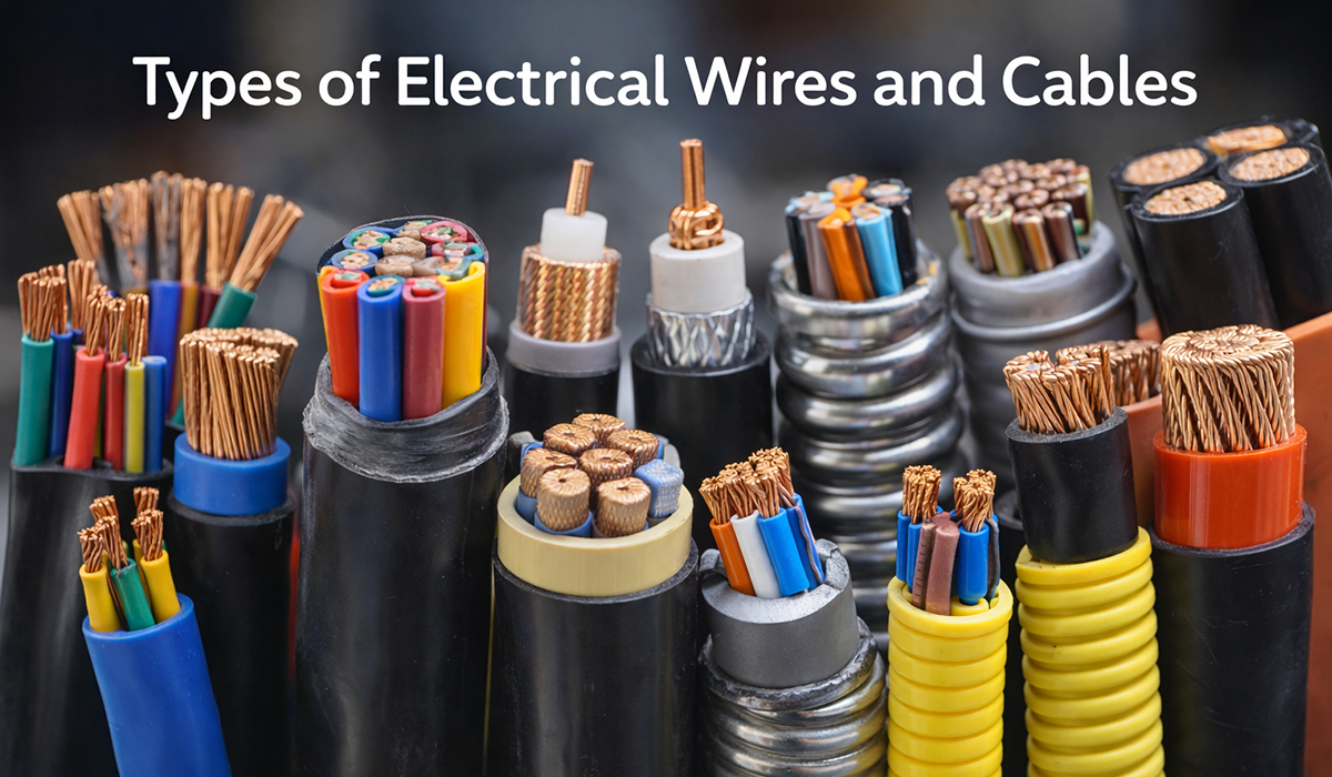
Rear access also affects how cables are routed into the lineup. To choose the right conductors, see our guide to electrical cable types.
Escape Routes and Doors
Aisles are also escape routes, and electrical room clearance requirements include them. Check these rules against your code:
- Exits: long lineups need an exit at each end, so nobody is trapped.
- Room doors: open outward, in the direction of escape, with panic hardware.
- Panel doors: when open, they must not block the escape route and should close in the direction of escape.
- Door swing: check every door swing on the plan.
How many exits does a switchgear room need? Often two, but exit distance limits come from IEC 61936-1 and local code.
The arc flash boundary is not a clearance rule. However, it shows where people stand during racking, so keep that zone clear. See our arc flash labels guide.
US code adds a firm trigger for panic hardware near large equipment. Electrical Contractor explains when doors must open outward with listed panic hardware in its NEC egress rules.
Escape routes matter most when an arc fault happens. For label rules and incident energy, read our arc flash labels reference guide.
US Rules: NEC 110.26 and 110.34
NEC 110.26 covers working space for equipment up to 1,000 V. In the simplest condition, it requires 3 ft of depth, 30 in of width and 6.5 ft of headroom. That answers how much clearance in front of electrical panel boards is needed.
NEC 110.34 covers equipment over 1,000 V. Its table sets depth by voltage and by what faces the live parts. For example, 2,501–9,000 V needs 4, 5 or 6 ft, depending on the condition.
In practice, the larger of NEC working space and the maker’s aisle applies. That electrical working clearance must stay clear, and under 110.26, equipment doors must open at least 90°.
The 110.34 table runs from 3 ft to 12 ft across five voltage rows. Electrical Contractor walks through the rows, the three conditions and a 4,160 V example in its NEC 110.34 guide.
The NEC covers many panel types beyond switchgear. For a simple overview, see our US electrical panels guide.
Conclusion: Minimum Aisle Widths in a Switchgear Room
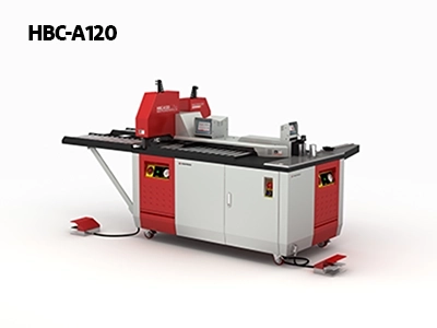
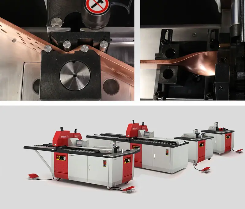
Electrical room design for a switchgear room starts with four checks. First, take the maker’s drawout aisle. Second, compare it with the standard’s minimum. Third, confirm rear access and the IAC sides. Fourth, check exits and door swing. These cover the switchgear clearance requirements most tenders ask about, so panel builders using PAYAPRESS machines can add them to tender packs.
Panel builders also need to prove their designs meet the rules. For the European route, read our IEC 61439 verification guide.


Rate this article
Choose a rating from 1 to 5 stars.
No ratings yet
0 Comments
No comments yet. Be the first to comment.