
Transformer busbars serve as the critical current-carrying backbone in power transformers, providing robust electrical connections between windings, tap changers, bushings, and terminals. Unlike flexible cables or braided leads, a properly engineered transformer busbar offers low-impedance, compact current pathways that withstand thermal cycling, electromagnetic forces during short-circuit events, and decades of service life while maintaining accessibility for maintenance and upgrades.
Understanding Transformer Busbar Fundamentals
In modern power transformers, the busbar in transformer assemblies must handle currents ranging from hundreds to thousands of amperes while occupying minimal space within the tank. The engineering challenge involves balancing electrical performance, mechanical strength, thermal management, and manufacturing feasibility. A well-designed busbar system reduces losses, prevents hotspots, and ensures reliable operation under both normal and fault conditions.
Consider a 50 MVA distribution transformer: the low-voltage side might carry 2,000 amperes continuously at 13.8 kV. The busbar connecting the LV winding to the bushing must conduct this current with minimal voltage drop (typically under 50 millivolts), resist electromagnetic forces during through-faults that can exceed 40 kA for several cycles, and accommodate thermal expansion without stressing the insulation system.
For a comprehensive understanding of busbar fabrication equipment, we highly recommend reviewing this article.
Material Selection: Copper vs. Aluminum Busbars
The choice between copper and aluminum for transformers with busbar connections involves multiple engineering trade-offs beyond simple cost comparison.
Copper Busbars
Copper remains the standard for high-current applications due to its superior conductivity (58 MS/m for annealed C110 grade) and excellent thermal stability. In a typical design, a 10mm × 100mm copper busbar can safely carry 1,200 amperes continuously with a temperature rise of 50°C in still air. Copper’s high stiffness also provides better mechanical support for cantilever connections and reduces vibration during fault events.
Real-world example: A major utility in California retrofitted their 1980s-era transformers with tin-plated copper bus bar transformer assemblies rated for 150°C operation, replacing the original unplated bars that showed oxidation after 25 years. The tin plating reduced contact resistance by 40% and extended the expected service life by another 30 years.
Aluminum Busbars
Aluminum offers weight savings of 67% compared to copper for equivalent current capacity, making it attractive for large power transformers where handling and shipping weight matter. However, aluminum requires 1.6 times the cross-sectional area to match copper’s conductivity. The lower density (2.7 g/cm³ vs. 8.9 g/cm³) still results in net weight reduction.
Critical consideration: Aluminum-to-copper joints demand special attention. Use tin or silver-plated contact surfaces and apply proper joint compound to prevent galvanic corrosion. A 500 kVA pad-mount transformer manufacturer in Texas switched to aluminum vs copper bus bar construction, achieving 15% cost reduction while maintaining performance by using oversized aluminum bars with welded connections instead of bolted joints.
| Specification | Copper | Aluminum |
|---|---|---|
| Conductivity (MS/m) | 58 | 35 |
| Density (g/cm³) | 8.9 | 2.7 |
| Thermal Expansion (10⁻⁶/°C) | 17 | 23 |
| Current Capacity (A/mm² at 50°C rise) | 1.2 | 0.8 |
| Relative Cost (per kg) | 3.5x | 1.0x |
| Typical Surface Treatment | Tin/Silver Plating | Oxide Removal + Compound |
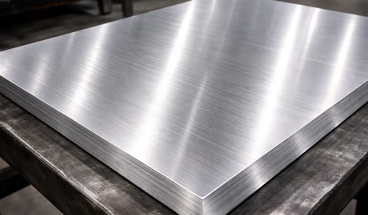
Cross-Section Design and Edge Treatment
The physical profile of materials for high current busbars significantly impacts both electrical and mechanical performance. Most transformer busbars use flat rectangular sections, but the edge treatment makes the difference between a reliable 30-year installation and premature failure.
Further exploration of Cross section can be found in the following recommended reading.
Radiused Edges and Burr Control
Sharp corners and burrs create electric field concentrations that initiate partial discharge and eventual insulation breakdown. Industry best practice calls for edge radii of at least 0.5mm, with 1-2mm preferred for high-voltage applications above 15 kV. After punching or cutting, all edges should be deburred to a maximum height of 0.1mm measured with a dial gauge.
A transformer manufacturer in Germany reduced field failures by 80% by implementing a two-stage deburring process: mechanical tumbling followed by hand finishing on bolt holes and bend radii where stress concentrations occur. Their quality control now rejects any busbar showing burrs exceeding 0.08mm at the joint landing zones.
Surface Finish for Joint Reliability
The contact surfaces where busbar transformer sections bolt together require special treatment. Tin plating (5-10 microns thick) over the joint areas provides a soft, corrosion-resistant interface that maintains low contact resistance over decades. Silver plating offers even better conductivity but costs 3-4 times more and tarnishes if exposed to sulfur compounds in the oil.
Hole Patterns, Slots, and Tolerance Management in Transformer Busbars
Precise hole location enables repeatable assembly and ensures proper alignment with mating bushings and terminals. For transformer busbar connection designs, establish a clear datum scheme—typically the intersection of two machined edges—and dimension all features from this reference.
If you are looking for more information about Transformer types, it is recommended not to miss reading this article.
Thermal Expansion Slots
Busbars can experience temperature swings of 80-100°C between cold start and full load. A 1-meter long copper bar expands approximately 1.7mm over this range. Slotted holes (oval slots with length 3-5mm greater than bolt diameter) at one end of the connection allow movement without stressing the joint or insulation.
Real-world implementation: A 138 kV transformer builder uses 12mm diameter bolts in 18mm × 12mm slots for connections exceeding 500mm length. The long axis of the slot aligns with the thermal expansion direction, and hardened washers distribute clamping force across the slot width.
Positional Tolerances
Modern CNC punching equipment achieves hole-to-hole tolerances of ±0.1mm for distances under 500mm. Specify tighter tolerances (±0.05mm) only where absolutely necessary for mating with precision-machined components like bushings. Looser tolerances (±0.2mm) suffice for holes used only for lifting or internal assembly.
Radius, Sequence, and Spring-Back in Transformer Busbars
Most transformer busbars require multiple bends to route current through the three-dimensional space inside the tank while maintaining clearances from grounded tank walls and other phases.
Minimum Bend Radius
The minimum inside radius for cold bending depends on material temper and thickness. For half-hard copper (H02), use a minimum of 1.5 times the material thickness. A 6mm thick bar would bend around a 9mm radius tool. Annealed (soft) copper tolerates tighter radii (1.0-1.2× thickness), while fully hardened aluminum requires 2-3× thickness to avoid cracking.
Always produce sample bends before committing to production. A Southeast Asian transformer factory discovered their 8mm aluminum bars could reliably bend to 12mm inside radius despite the supplier recommending 16mm—saving significant material and space in their compact distribution transformer design.
Spring-Back Compensation
All metals spring back after bending, with the unbent angle typically 2-6° less than the tool angle. Spring-back increases with material hardness and yield strength. Modern encoder-equipped hydraulic benders store spring-back profiles for different materials and can automatically overbend by the calculated amount.
Practical approach: Measure the first article under no-load conditions, then verify the angle under the actual bolt-up load. A 90° connection might require bending to 84° to achieve 90° after spring-back, but when clamped with M12 bolts at 80 Nm torque, it settles to exactly 90°.
For a comprehensive understanding of rules of bending, we highly recommend reviewing this article.
Bend Sequence for Multi-Plane Parts
Complex bus bar in transformer geometries with bends in multiple planes require careful sequence planning. Each bend shifts the reference edges, so later bends inherit cumulative error from earlier operations. Best practice: Position critical dimensions (bolt hole locations, mating surfaces) near the first bends in the sequence where tolerances remain tightest.
Example sequence for an LV connection with three 90° bends: First bend forms the vertical leg leaving the winding; second bend routes horizontally toward the bushing; third bend aligns the final tab with the bushing mounting plane. Punch all holes in the flat pattern before any bending to maintain the tightest possible hole-to-hole accuracy.
If you are looking for more information about Bend Sequence, it is recommended not to miss reading this article.
Insulation, Sleeving, and Electrical Clearances
Proper insulation prevents flashover between busbars, from busbar to tank, and along creepage paths on the busbar surface. The insulation system must withstand the transformer’s rated voltage plus test overvoltages (typically 2× rated) and resist degradation from oil, heat, and moisture over the design life.
Temperature Class and Material Selection
Most transformer transformer bus bar insulation uses Class F (155°C) or Class H (180°C) materials. Common options include fiberglass sleeves, polyester tapes, and epoxy-bonded barriers. The insulation must remain flexible through repeated thermal cycling and not become brittle or cracked.
Re-sleeving after bending: If insulation sleeves don’t conform to tight bend radii, remove them before forming, then slide new sleeves over the bent section. Mark the drawing with a note: “Re-sleeve bend areas with 2 layers Class H fiberglass after forming, overlap 50mm minimum.”
Creepage and Clearance Requirements
Clearance (shortest air distance) and creepage (shortest surface distance) depend on the system voltage and pollution environment. For a 35 kV transformer in a clean indoor substation, specify minimum 75mm air clearance and 100mm creepage. Outdoor or contaminated environments require 50-100% greater distances.
Avoid sharp points and edges that concentrate electric fields. A 2mm radius edge at 20 kV might create a field intensity of 15 kV/mm—well above the 3 kV/mm threshold for corona onset in transformer oil. Rounding to 5mm radius drops the peak field to under 5 kV/mm, eliminating discharge risk.
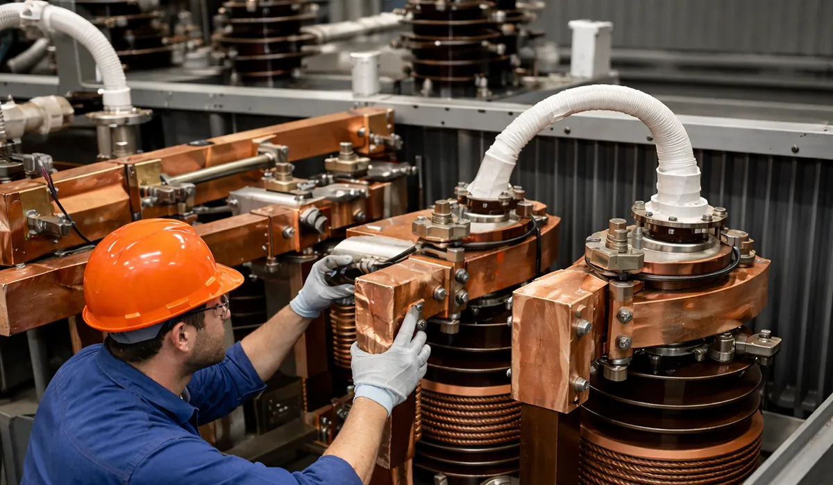
Fabrication Workflow: Equipment and Process Control in Transformer Busbars
Modern busbar fabrication relies on specialized machinery that combines punching, cutting, and bending in controlled sequences to achieve the tight tolerances required for transformer busbar assemblies.
For a comprehensive understanding of Busbar Manufacturing Workflow, we highly recommend reviewing this article.
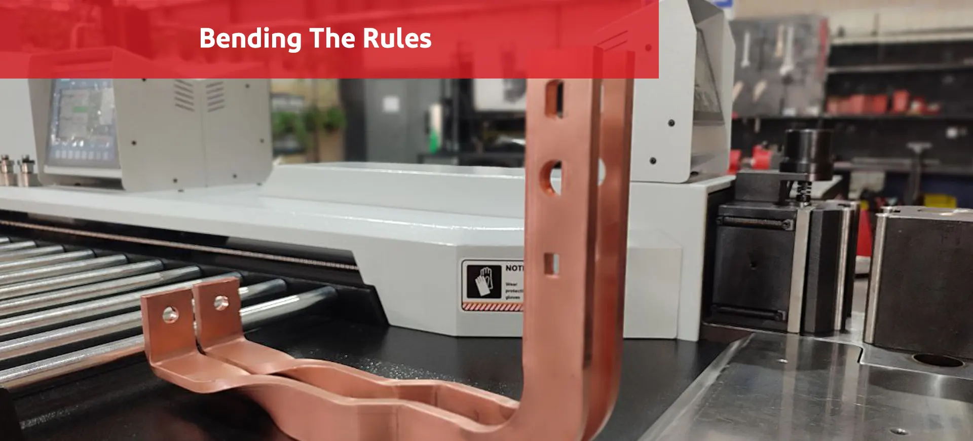
Bending the Rules: A Deep Dive into Busbar Bending Techniques
In the world of electrical engineering and power distribution, busbars play a pivotal role. These essential components, typically made from copper or aluminum, serve as
Hydraulic Punch-and-Cut Stations
These machines use interchangeable round, oval, and rectangular dies to create holes and slots in bar stock up to 15mm thick. Laser centering systems project alignment marks onto the workpiece, allowing operators to position holes with ±0.1mm repeatability. Roller supports prevent sagging on long bars (over 2 meters), which would introduce angular errors in the punched features.
Typical die set for transformer work: M12, M16, M20 round punches (for standard bolt sizes), plus 18×12mm and 24×16mm oval dies for thermal expansion slots. A quick-change tool holder lets operators swap dies in under 2 minutes without recalibration.
Encoder-Assisted Hydraulic Benders
Precision bending machines incorporate angle encoders on the ram and backgauge, storing spring-back correction curves for different materials. The operator inputs material type (copper C110, aluminum 6101, etc.), thickness, and target angle; the control system automatically calculates the overbend amount.
Process capability: A well-maintained bender with 0.01° encoder resolution can hold ±0.5° on 90° bends in 6mm copper bar. For tighter requirements (±0.25°), perform a first-article measurement and manually fine-tune the stored profile.
Cell Layout: 3-in-1 vs. Dedicated CNC Lines
Low to medium volume shops (under 500 busbar assemblies per month) often choose compact 3-in-1 machines that punch, cut, and bend in a single 4-meter footprint. These units handle bar widths up to 200mm and thicknesses to 12mm, suitable for most distribution and medium power transformer applications.
High-volume manufacturers invest in CNC lines with automatic material feeding, nesting optimization, and integrated quality inspection. A fully automated line can process 200 parts per shift with one operator, versus 50-80 parts per shift on manual equipment. The throughput gain justifies the 4-5× higher capital cost when production exceeds 2,000 assemblies monthly.
Quality Control and Inspection Procedures in Transformer Busbars
Rigorous inspection at each fabrication stage prevents defects from propagating downstream and ensures every busbar in transformer meets specification before assembly.
Cut and Punch Verification
Measure burr height with a dial gauge across all punched holes and cut edges; reject parts exceeding 0.1mm burr height (or tighter if specified). Check hole position using a CMM or optical comparator for the first article and every 50th part in production runs. Verify center-to-center distances against drawing dimensions with ±0.15mm tolerance.
Bend Quality Checks
Use a digital angle gauge to measure all bends: ±1° is typical production capability; ±0.5° is achievable with proper setup. Inspect inside radii visually for cracking or thinning; any visible crack is cause for rejection. Check overall flatness by placing the part on a surface plate and measuring gaps with feeler gauges—maximum twist of 2mm per meter length is acceptable for most applications.
Surface Preparation and Plating
Before plating, clean all joint surfaces with isopropyl alcohol or approved solvent to remove oils and oxidation. After tin or silver plating, measure coating thickness with an XRF analyzer: target 7-10 microns for tin, 5-8 microns for silver. Test plating adhesion by bending a scrap sample 90° over a 10mm radius—the coating should not flake or crack.
Insulation Coverage Inspection
Verify insulation sleeves cover the specified areas with required overlaps (typically 25-50mm). Check for damage caused by bending—tears or crushed sections reduce dielectric strength. For critical applications, perform hi-pot testing at 2× rated voltage plus 1000V for one minute; observe for any leakage current or breakdown.
Further exploration of List of IEC standards can be found in the following recommended reading.
RFQ Best Practices: How to Get Accurate Quotes Quickly
Providing complete information up front reduces quote turnaround time from 2-3 weeks to 3-5 days and minimizes costly mid-production changes.
Technical Documentation Checklist
Supply a 3D STEP or IGES model if available, or a detailed 2D flat pattern showing all dimensions, bend lines with radii and direction arrows, and bend sequence numbers. Include a hole/slot table listing every feature: diameter or slot dimensions, positional tolerances, and datum references. Specify material grade (not just “copper” or “aluminum”), temper (soft/half-hard/hard), thickness and width with tolerance, and surface finish requirements (bright, pickled, as-rolled).
Finish and Processing Requirements
Clearly state edge treatment: radius specification, maximum burr height, and whether deburring is manual or tumbled. Define plating needs: type (tin/silver), thickness, and coverage area (all over, joint surfaces only, selective masking). Document insulation requirements: material class, layer count, overlap distances, and whether sleeving occurs before or after bending.
Quality and Delivery Parameters
Specify quantities (prototype, pilot, production) and batch sizes if applicable. State target lead time and indicate flexibility—rush orders cost 20-40% premium but may deliver in half the normal time. List required certifications: material test reports, dimensional inspection records, hi-pot test data. Include packing instructions: prevent oxidation during shipping by sealing in VCI bags; label each part with drawing number and serial number for traceability.
If you are looking for more information about RFQ Best, it is recommended not to miss reading this article.
Frequently Asked Questions


Transformer busbars are essential for handling high currents safely and efficiently. Their solid design improves conductivity and helps reduce power losses in electrical systems.