
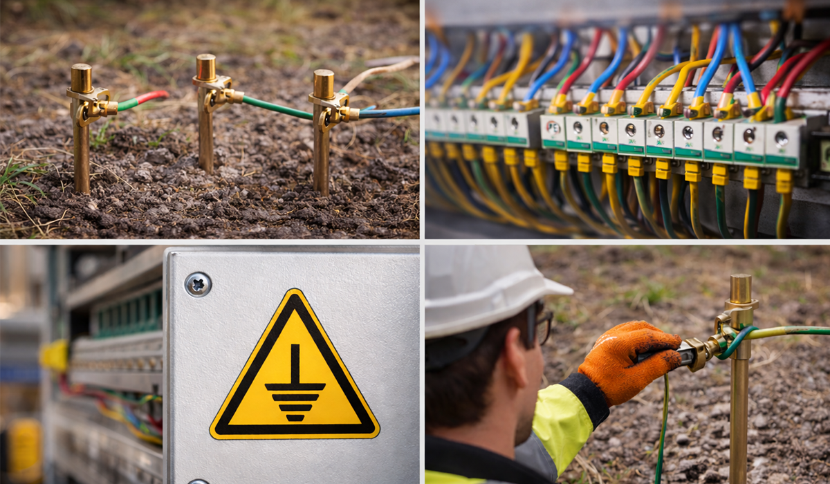
Earthing (or grounding) is a fundamental aspect of electrical installations, ensuring safety and reliability. It involves the connection of electrical systems or equipment to the conductive mass of the earth, which helps stabilize voltages and provides a safe return path for fault currents. This guide explains the core principles of earthing systems, their importance, and how to select the appropriate system for different installations, in alignment with the international standard IEC 60364.
If you’d rather listen than read, feel free to play the audio file below for the rest of this article.
Earthing & Grounding Systems: A Complete Technical Guide
If the information about Earthing was valuable and interesting to you, researching Standards on Switchgear and Busbars could be just as captivating.
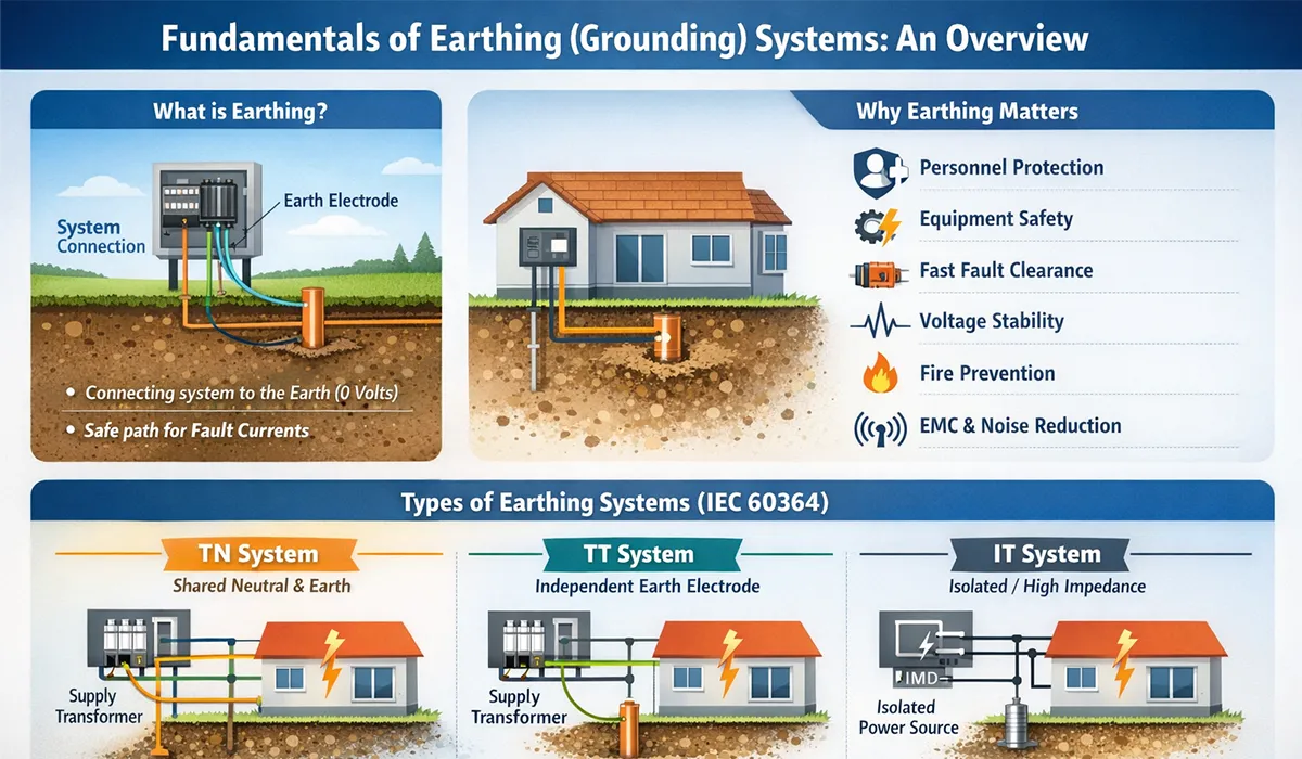
What Is Earthing (Grounding)?
Earthing — also called grounding — is the deliberate electrical connection of a system or equipment to the conductive mass of the earth, which is conventionally taken as having a potential of zero volts. This zero-reference point stabilizes voltages across the entire system, and provides a safe, low-resistance return path for fault currents.
The earth itself is a reasonably good conductor, particularly when moist. Its enormous cross-sectional area reduces current density, which in turn reduces voltage drop. This makes it suitable not only as a safety reference but also — in some high-voltage DC transmission systems — as a return conductor.
If the information related to Grounding Systems was interesting and informative to you, researching Earthing system can be very engaging.

Why Earthing Matters: Key Benefits
A properly designed and implemented earthing system provides several critical benefits:
- Personnel protection — Limits touch voltage to safe levels (below 50 V) in fault conditions.
- Equipment protection — Prevents dangerous overvoltages from damaging insulation and connected devices.
- Fast fault clearance — Enables protective devices (fuses, MCBs, RCDs) to operate quickly by providing a low-impedance fault path.
- System voltage stability — Grounds the neutral point, preventing excessive voltage rises on healthy phases during a fault.
- Fire prevention — Reduces the risk of arcing and thermal damage from uncontrolled fault currents.
- Electromagnetic compatibility (EMC) — Provides a stable reference that reduces electrical noise and interference.
Further exploration of Voltage regulator can be found in the following recommended reading.
Core Concepts & Definitions
Earth Electrode
One or more metal parts (rods, plates, or bare conductors) buried in the ground to create an electrical connection with the earth mass. The resistance of the electrode depends on soil resistivity, electrode size, and burial depth.
Earthing Conductor
The conductor that connects the earth electrode to the main earthing terminal (MET) or main earthing busbar inside the installation.
Protective Conductor (PE)
A conductor connecting the MET to the exposed conductive parts (ECPs) of equipment enclosures. In normal operation, no current flows through it — it only carries current during a fault.
PEN Conductor
A combined conductor that fulfills the roles of both the neutral (N) and protective earth (PE). Used in TN-C configurations; not permitted in circuits downstream of RCDs.
Touch Voltage
The potential difference between an energized enclosure and the ground at the point where a person is standing. Values above 50 V AC are considered dangerous and may cause serious electric shock or death.
Extraneous-Conductive-Parts
Metal parts not part of the electrical installation but capable of introducing earth potential — such as structural steel, metal water or gas pipes, radiators, and HVAC ducting. These must be connected to the MET through main equipotential bonding.
For a comprehensive understanding of Types of Earthing Systems, we highly recommend reviewing this article.
Types of Earthing Systems (IEC 60364)
The international standard IEC 60364 defines earthing systems using a two- or three-letter code. The first letter describes how the power source (transformer or generator) is related to earth. The second letter describes how the exposed conductive parts of the consumer installation are earthed. Optional third letters (S or C) describe the arrangement of neutral and protective conductors.
For a comprehensive understanding of (IEC 60364) we highly recommend reviewing this article.
| Letter | Stands For | Meaning |
|---|---|---|
| T (1st) | Terra (Earth) | One point of the source is directly connected to earth. |
| I (1st) | Isolated / Impedance | The source is isolated from earth, or connected via high impedance. |
| T (2nd) | Terra (Earth) | Exposed conductive parts are directly earthed, independently of the source. |
| N (2nd) | Neutral | ECPs are connected to the earthed neutral point of the source. |
| S (3rd) | Separate | Protective earth (PE) and neutral (N) are separate conductors throughout. |
| C (3rd) | Combined | Neutral and protective earth functions are combined into a single PEN conductor. |
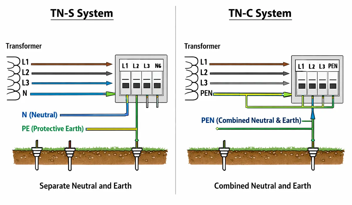
TN Systems — Source and Installation Share the Same Earth
In TN systems, the neutral point of the supply transformer is directly earthed, and the exposed conductive parts of consumer installations are connected back to that earthed neutral via a PE or PEN conductor. This creates a low-impedance fault loop, allowing overcurrent devices (fuses and MCBs) to respond quickly to earth faults.
TN-S — Fully Separated PE and Neutral
The PE and neutral conductors remain entirely separate throughout the installation — from the source all the way to each outlet. This is the safest TN variant, offering low electromagnetic interference and reliable protection. It is standard in modern industrial, commercial, and residential installations across Europe.
TN-C — Combined PEN Conductor
The neutral and protective functions are merged into a single PEN conductor. This reduces wiring costs but at the expense of safety: if the PEN conductor breaks, all downstream metalwork may rise to line voltage. It is common in older utility distribution networks in North America and Eastern Europe, but is not recommended for new industrial or commercial installations.
TN-C-S — Split at the Service Head (PME)
The most widely used arrangement in the UK and many other countries. The supply network uses a PEN conductor (TN-C), which then splits into separate PE and N at the consumer’s service head (TN-S). This is known as Protective Multiple Earthing (PME) in the UK. It offers low loop impedance for reliable fault disconnection. However, a broken PEN upstream can impose dangerous voltages on all earthed metalwork — so equipotential bonding must be meticulously implemented.
If the information about TN Systems was valuable and interesting to you, researching topic Y could be just as captivating.
TT System — Independent Consumer Earth
In a TT system, the transformer neutral is earthed by the utility, but the consumer’s exposed conductive parts are connected to a completely separate, independent earth electrode at the installation site. There is no metallic earth return path between source and consumer — the only return path for fault current is through the two independent earth electrodes and the mass of the earth itself.
This results in high fault loop impedance, meaning that fuses and MCBs alone cannot be relied upon to disconnect faults quickly. Residual Current Devices (RCDs) are therefore mandatory in TT installations. Despite this requirement, TT systems offer excellent noise immunity and are preferred for:
- Telecommunications and data centers requiring a clean earth reference
- Rural or remote installations served by overhead lines
- Areas where the integrity of a shared PEN conductor cannot be guaranteed
This article serves as a valuable resource for those seeking detailed information on TT System.
IT System — Isolated or High-Impedance Source
In an IT system, the power source is either completely isolated from earth or connected to it through a high impedance. This means that when a first earth fault occurs, the resulting fault current is extremely small — limited only by the distributed capacitance of the cables to earth. The system can continue operating safely through a first fault, without any power interruption.
An Insulation Monitoring Device (IMD) continuously measures the insulation resistance of the entire system and alerts operators when a first fault is detected. The fault must be located and corrected before a second fault occurs on a different phase — because two simultaneous faults would result in a full short circuit.
IT systems are the system of choice wherever uninterrupted power supply is critical, including:
- Hospital operating theatres and intensive care units
- Mining and underground facilities
- Industrial processes where a sudden shutdown would be dangerous or costly
- Offshore oil platforms and marine applications
Further exploration of Information technology can be found in the following recommended reading.
Comparison of TN, TT, and IT Systems
| Feature | TN (S / C-S) | TT | IT |
|---|---|---|---|
| Source connection to earth | Direct (neutral earthed) | Direct (neutral earthed) | Isolated or high impedance |
| Consumer earth connection | Via shared neutral / PE | Independent local electrode | Independent local electrode(s) |
| Fault loop impedance | Low | High | Very high (first fault) |
| First fault current | High (enables fast disconnection) | Moderate (requires RCDs) | Very low — system remains operational |
| Required protective device | MCB / Fuse / RCBO | RCD (mandatory) | Insulation Monitoring Device (IMD) |
| Service continuity | Interrupted on fault | Interrupted on fault | Maintained through first fault |
| EMC / Noise immunity | Moderate (TN-S) / Poor (TN-C) | Excellent | Good |
| Maintenance complexity | Low | Low–Moderate | High (continuous monitoring required) |
| Cost | Low–Moderate | Moderate | High |
| Typical applications | Homes, offices, factories | Telecoms, rural areas, sensitive sites | Hospitals, mines, offshore, critical industry |
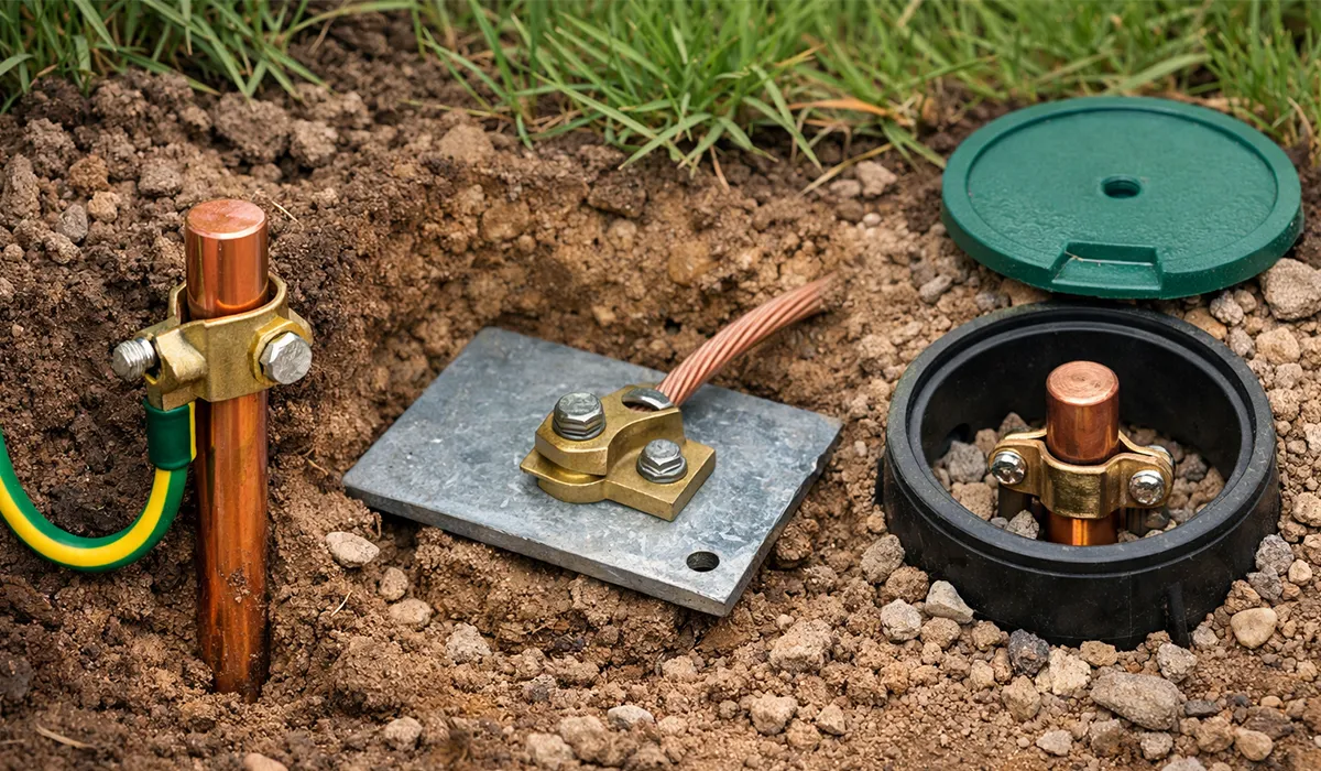
Types of Earth Electrodes
The choice of electrode type depends on available space, soil conditions, required resistance value, and installation depth.
Further exploration of Earth Electrodes can be found in the following recommended reading.
| Electrode Type | Description | Typical Application | Notes |
|---|---|---|---|
| Plate Electrode | Copper or galvanized steel plate (≥ 0.5 × 0.5 m), buried vertically | Moist, humid areas with shallow rock | Surrounded by bentonite to retain moisture; minimum soil cover 1.5 m |
| Rod / Pipe Electrode | Copper-bonded steel rod (≥ 2 m length) driven vertically into ground | Most common type; general use | Can be extended with couplers; installed near distribution board |
| Horizontal Strip / Ring Electrode | Bare copper conductor buried horizontally at 0.5–0.8 m depth | Large sites with sufficient area; rocky terrain unsuitable for rods | Can surround a building as a ring earth electrode |
| Foundation Electrode | Conductor embedded in concrete foundation of a building | New construction; preferred for permanent installations | Cost-effective and long-lasting; requires coordination at design stage |
Soil Resistivity and Earth Resistance
The effectiveness of an earthing system depends critically on the resistivity of the surrounding soil. Soil resistivity (measured in Ω·m) varies widely based on mineral composition, moisture content, and temperature.
If the information related to Soil Resistivity was interesting and informative to you, researching Methods of Measuring Earth Resistance can be very engaging.
| Soil Type | Typical Resistivity (Ω·m) | Comments |
|---|---|---|
| Moist clay / garden soil | 10 – 100 | Excellent for earthing; low resistance achievable |
| Loam / agricultural land | 50 – 200 | Generally suitable; moisture-dependent |
| Sandy soil (moist) | 100 – 500 | Acceptable with deeper or multiple electrodes |
| Gravel / dry sand | 500 – 2000 | Challenging; bentonite or conductive backfill required |
| Rock / dry granite | 1000 – 5000+ | Very high resistance; horizontal or deep electrodes needed |
To maintain low electrode resistance in high-resistivity soils: use longer or multiple rods, install bentonite or conductive salt backfill around the electrode, or use a moisture maintenance pipe for controlled water injection.
Equipotential Bonding
Main Equipotential Bonding
All significant metal services entering a building must be bonded together and connected to the Main Earthing Terminal (MET). This includes metal water pipes, gas pipes, structural steel, HVAC ducting, and telecommunications conduits. The goal is to ensure that all simultaneously touchable conductive parts remain at the same potential — eliminating the risk of dangerous touch voltage between them.
Supplementary Equipotential Bonding
In locations where the disconnection time of protective devices cannot be guaranteed to meet required limits — particularly in wet environments such as bathrooms, swimming pools, saunas, and agricultural buildings — supplementary bonding is mandatory. All simultaneously accessible conductive parts (equipment enclosures, pipes, structural metal) must be directly connected together.
Further exploration of Electrical bonding can be found in the following recommended reading.
Grounding System for Low-Voltage Networks
The low-voltage secondary side of distribution transformers must be grounded to protect against overvoltages arising from two specific failure modes:
- A broken high-voltage overhead conductor falling onto the low-voltage network
- Internal insulation breakdown causing the primary winding to fault onto the secondary winding
Without grounding, anyone touching the low-voltage network or transformer enclosure in either scenario would receive a potentially lethal high-voltage shock. With proper grounding, the primary-side fuses blow immediately, disconnecting the fault and protecting both people and equipment.
If the material related to topic X was both useful and intriguing to you, diving into topic Y will likely be equally fascinating.
Protective Devices and Their Role in Earthing Systems
| Device | Earthing System | Function |
|---|---|---|
| Fuse / MCB | TN (low loop impedance) | Clears high-current earth faults rapidly by overcurrent tripping |
| RCD (Residual Current Device) | TT (high loop impedance) | Detects imbalance between line and neutral currents; trips on leakage as low as 30 mA |
| RCBO | TN-S / TN-C-S | Combined MCB and RCD in one device — provides both overcurrent and residual-current protection |
| Insulation Monitoring Device (IMD) | IT systems | Continuously monitors insulation resistance; alarms on first fault without tripping |
Measuring and Verifying Earth Resistance
Earth resistance must be measured and verified at installation and re-checked periodically (at minimum every few years, or after any significant ground disturbance). The standard measurement method uses a Megger earth tester with four terminals — two for injecting a test current and two for measuring the resulting voltage.
Key measurement points include:
- Earth electrode resistance (Ra) — resistance of the local earth electrode to true earth
- Earth fault loop impedance (Zs) — total impedance of the fault current path, used to verify protective device operation times
- Continuity of protective conductors — to confirm no breaks in the PE path
If the material related to Grounding System for Low-Voltage Networks was both useful and intriguing to you, diving into Low Voltage Assemblies will likely be equally fascinating.
Conclusion
In conclusion, a properly designed earthing system is crucial for ensuring the safety of personnel and equipment, protecting against overvoltages, and enabling fast fault clearance. By understanding the different types of earthing systems and their applications, as well as the role of various protective devices, it becomes clear that earthing is not just a regulatory requirement but an essential practice to maintain the integrity of electrical systems. Whether in residential, industrial, or critical applications, selecting the right earthing system enhances safety, minimizes risks, and optimizes system performance.


