



If you’d rather listen than read, feel free to play the audio file below for the rest of this article.
The 4 Compartments at a Glance
| Compartment | Where it sits | What it holds | Typical access |
|---|---|---|---|
| Busbar | Top or rear | Main busbars | Rarely, with the line-up dead |
| Circuit-breaker | Front middle | Breaker truck, shutters | Often, through the front door |
| Cable | Rear or lower | Cable terminations, CTs, earthing switch | After earthing |
| Low-voltage | Front top | Relays, meters, wiring | In service |
The order is not random. Heavy, rarely touched parts sit at the back and top, while the parts that people operate or inspect sit at the front, within easy reach. In mv switchgear, this split keeps routine work well away from the main busbars.
If you are new to these systems, start with our guide to switchgear basics. It shows how a full lineup fits together before you study each compartment.
1. Busbar Compartment
The busbar compartment sits at the top or rear of the panel. It holds the main busbars, which run through the whole lineup and connect every panel to the same supply. Because every feeder depends on them, the compartment usually stays closed while the switchgear is in service.
Bushings or partitions often divide the busbars from one panel to the next, so a fault stays local. The bars themselves are thick copper, sized for the rated current and for the forces of a short circuit.
2. Circuit-Breaker Compartment
The circuit breaker compartment sits in the front middle. It holds the withdrawable circuit breaker, or a contactor or switch, on its truck. The truck racks between service, test and disconnected positions, so nobody has to open a bolted joint.
When the truck rolls out, metal shutters drop over the live contacts, and the operator never faces exposed high voltage. For this reason, staff open this box more often than any other, for racking, testing and breaker maintenance. Interlocks also keep the door shut while the truck sits in the service position.
3. Cable Compartment
The cable compartment fills the rear or lower part. It holds the cable terminations, the current transformers and the earthing switch. It often holds a voltage transformer or surge arresters too. So, if you ask which compartment has the current transformers, the answer is usually this one.
Before anyone opens it, the earthing switch connects the outgoing cables to earth. As a result, crews can terminate or test cables safely. Space matters here as well, because large cross-sections and several cables per phase need room to bend.
4. Low-Voltage Compartment
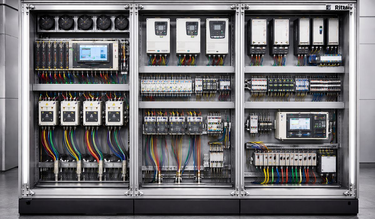
The low voltage compartment is the box at the front top. It holds the protection relay, meters, control switches, terminals and the auxiliary wiring that links them. Because metal walls separate it from the high-voltage parts, technicians can open it safely while the panel stays in service.
In practice, most commissioning and fault-finding happens here. The relay reads signals from the current and voltage transformers below and trips the breaker when it sees a fault. Wiring ducts then carry these control circuits from panel to panel.
Real switchgear compartments follow this same plan in most air-insulated designs. For example, ABB shows units of up to five compartments, split by metal partitions, in its switchgear technical guide.
Each compartment is built from many smaller parts. Our overview of switchgear components explains what they are and how they work together.
Why Compartments Matter
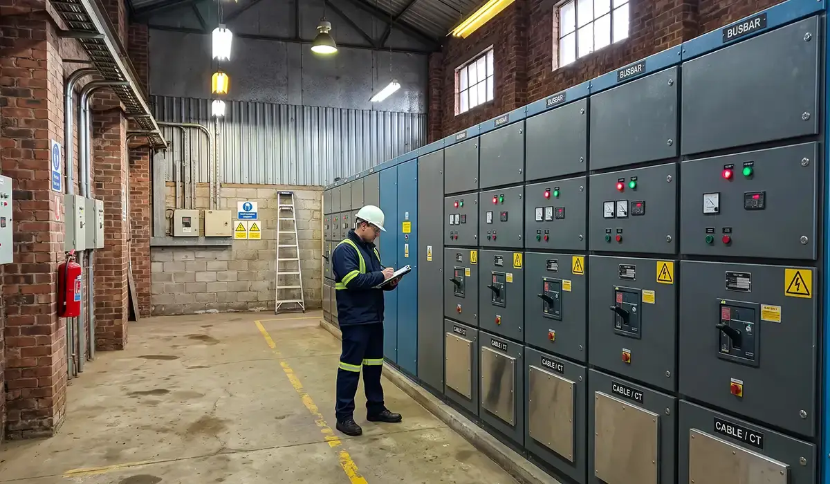
Switchgear is divided into compartments for two reasons: safe access and arc containment. First, earthed metal partitions keep other boxes live as you open one, which is the basis of LSC2B. For example, a crew can work on one feeder’s cables while the busbars above keep feeding the rest of the lineup.
Second, the partitions trap an internal arc in one box. Each high-voltage compartment usually has its own pressure relief flap (link: Brief 19 URL), which lets hot gas escape upward instead of through the front doors. Consequently, the damage stays in one box, and people in front of the panel are better protected.
The same idea explains two names you will meet in tenders. Metal clad switchgear is the US name for this fully compartmented design with a withdrawable breaker. In contrast, metal enclosed switchgear is the wider family, which also covers designs with fewer partitions or fixed devices.
These partition rules come from IEC 62271-200, the standard for AC metal-enclosed switchgear above 1 kV. Schneider Electric explains which compartments may stay energized in its LSC2B FAQ page.
The fully compartmented design is most common in withdrawable panels. To see how these panels are built, read our metal-clad switchgear guide.
Conclusion: The 4 Compartments of MV Switchgear
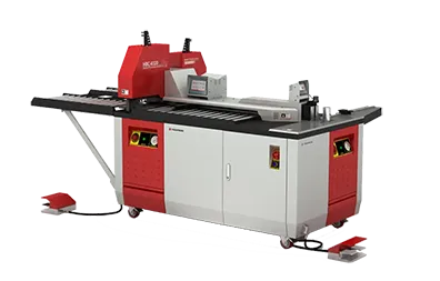
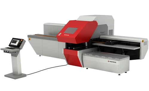
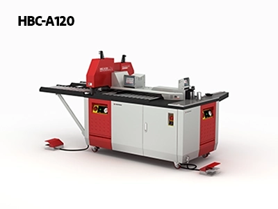
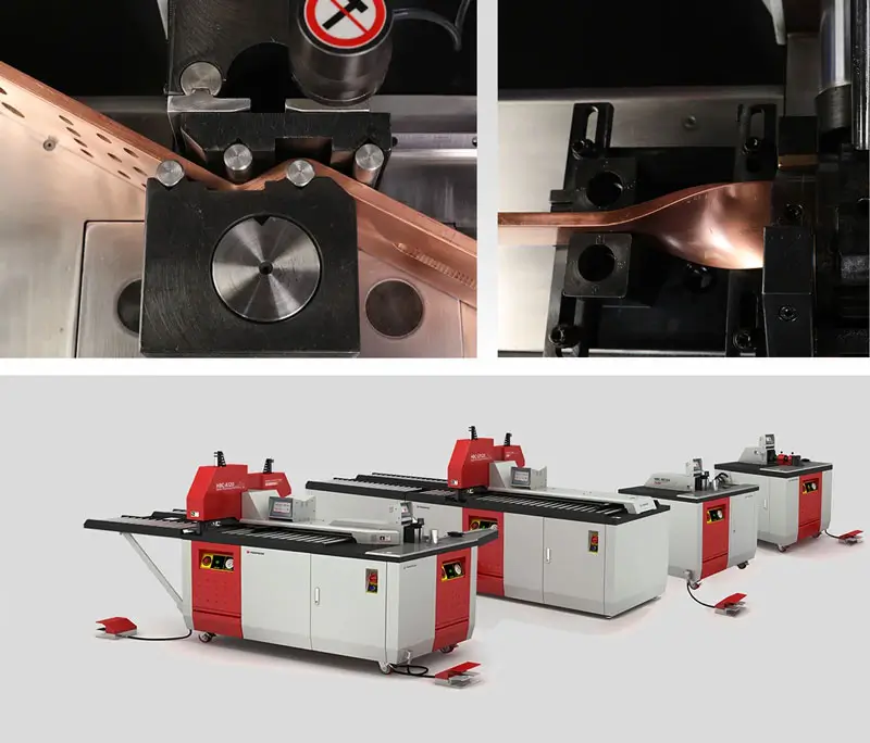
These medium voltage switchgear compartments give four jobs one safe layout: busbars at the back, the breaker in the middle, cables below and controls on top. Once you can picture that panel, datasheets and drawings read much faster. Moreover, three of the four boxes are built around copper busbar, which PAYAPRESS machines cut, punch and bend with precision.
Busbars are the backbone of every compartment layout. Learn more about the role of busbars in modern electrical systems.



Rate this article
Choose a rating from 1 to 5 stars.
No ratings yet
0 Comments
No comments yet. Be the first to comment.