








If you’d rather listen than read, feel free to play the audio file below for the rest of this article.
What a Corner Forming Machine Actually Does
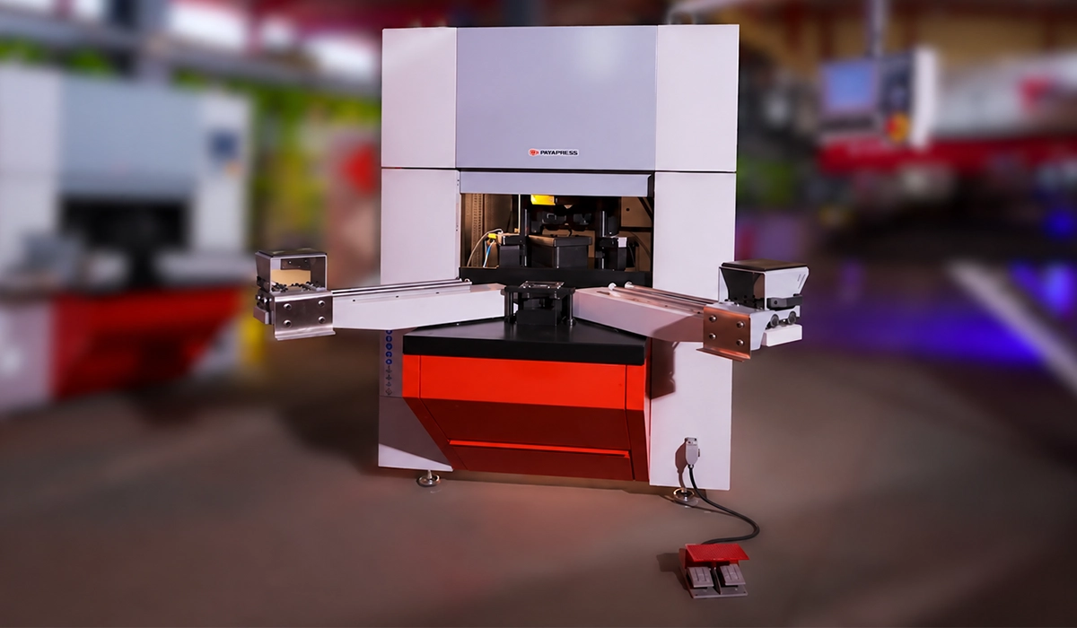
The machine closes an open corner to a set radius, R6 to R30 mm on the CFCM-30. It cold-rolls the standing flange around a die instead of welding it. Understanding how to use a corner forming machine starts with what one stroke does to the metal.
- Pre-bend the two adjacent sides to 90° on a press brake.
- Seat the open corner on the forming die.
- The forming roller cold-forms the corner in one stroke.
- Trim the excess flash at the shear station.
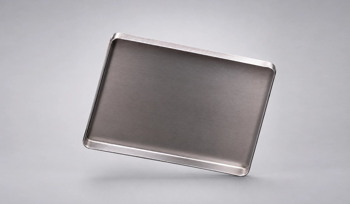
The corner forming process is cold plastic deformation of the flange material around the corner. Nothing gets cut away and rejoined. Fabricators call the result an R-corner, after its defining radius. The corner leaves as one continuous piece of metal: no weld seam, no grinding, no polishing.
Corner demands vary by product: see cold formed corner applications. in this page.

Before the Sheet Reaches the Machine
Most corner faults are born upstream. The corner cut-out goes into the flat blank at laser or punch stage, and its geometry decides how the flange behaves under the roller. Cut it short and the corner starts open. Cut it long and surplus material bunches at the tip.
Pre-bending on a press brake comes next. A sheet metal corner forming machine does not bend the panel walls — it only closes what the brake has already turned up. A pre-bent sheet with inconsistent angles between its two sides will not form evenly, whatever the corner former does.
Then the limits. The sheet thickness range for corner forming is 0.5–2 mm overall, but each material narrows that band, and the minimum piece size for corner forming is 210 × 210 mm.
| Parameter | Value |
| Sheet thickness range (overall) | 0.5 – 2 mm |
| Oiled sheet (ST12) | 0.8 – 2 mm |
| Black sheet (ST37) | 1.5 – 2 mm |
| Stainless steel | 0.8 – 2 mm |
| Forming radius range | R6 – R30 mm |
| Minimum piece size | 210 × 210 mm |
| Machine overall dimensions (W × D × H) | 1420 × 1200 × 1850 mm |
Those bands are not arbitrary. Oiled ST12 is a drawing-quality cold-reduced sheet and takes the radius easily. Black ST37 is hot-rolled, harder, carries mill scale, and needs 1.5 mm before it forms cleanly. Stainless work-hardens fastest of the three, so expect it to open further after the roller lifts.
Corner cut-out geometry starts one step earlier still: see corner notching before forming.
The Controls You Will Actually Touch
A metal corner forming machine has fewer controls than a press brake. An operator meets all of them in the first hour.
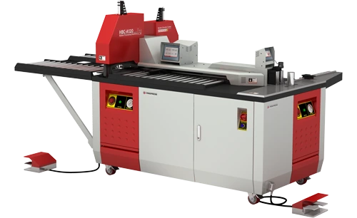
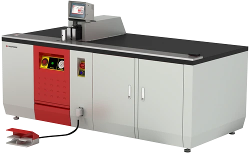
The 7-inch HMI carries the job screen, with a Delta PLC behind it and the start, stop and emergency-stop cluster beside it. You select thickness and radius here, and nothing else needs setting once the job is loaded.
The foot pedal starts the cycle. That matters more than it sounds: it keeps both hands on the sheet, where they are needed to hold the flange against the die faces.
The pneumatic sheet holder solves a specific problem. A large plate lifts or drifts sideways as forming pressure builds, and hand pressure alone will not stop it. Clamp the plate and the corner stays put.
The movable support arm does the same along the length of the panel. Without it, a long workpiece hangs cantilevered off the table, and the operator’s grip fights gravity instead of holding the corner.
Behind all of this sits a 4.5 kW machine running a 200 bar hydraulic circuit off a 50 L tank. That reservoir size relative to the power draw lets the machine run corner after corner without the oil heating enough to shift its viscosity. That is the difference between a sample part and a full shift.
Step 1: Forming
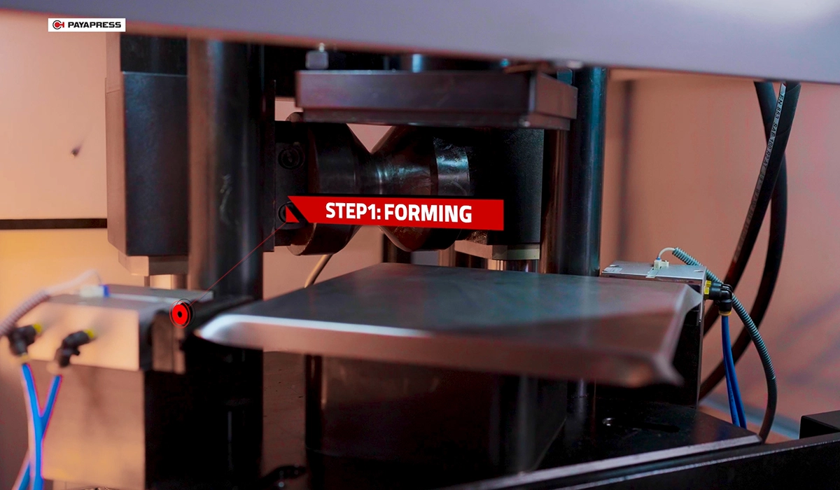
Forming produces a closed corner in a single stroke, provided the die gap sits at roller radius minus sheet thickness and the flange is pulled tight before the cycle starts.
The sequence runs as follows.
- Select the job on the HMI — sheet thickness and corner radius.
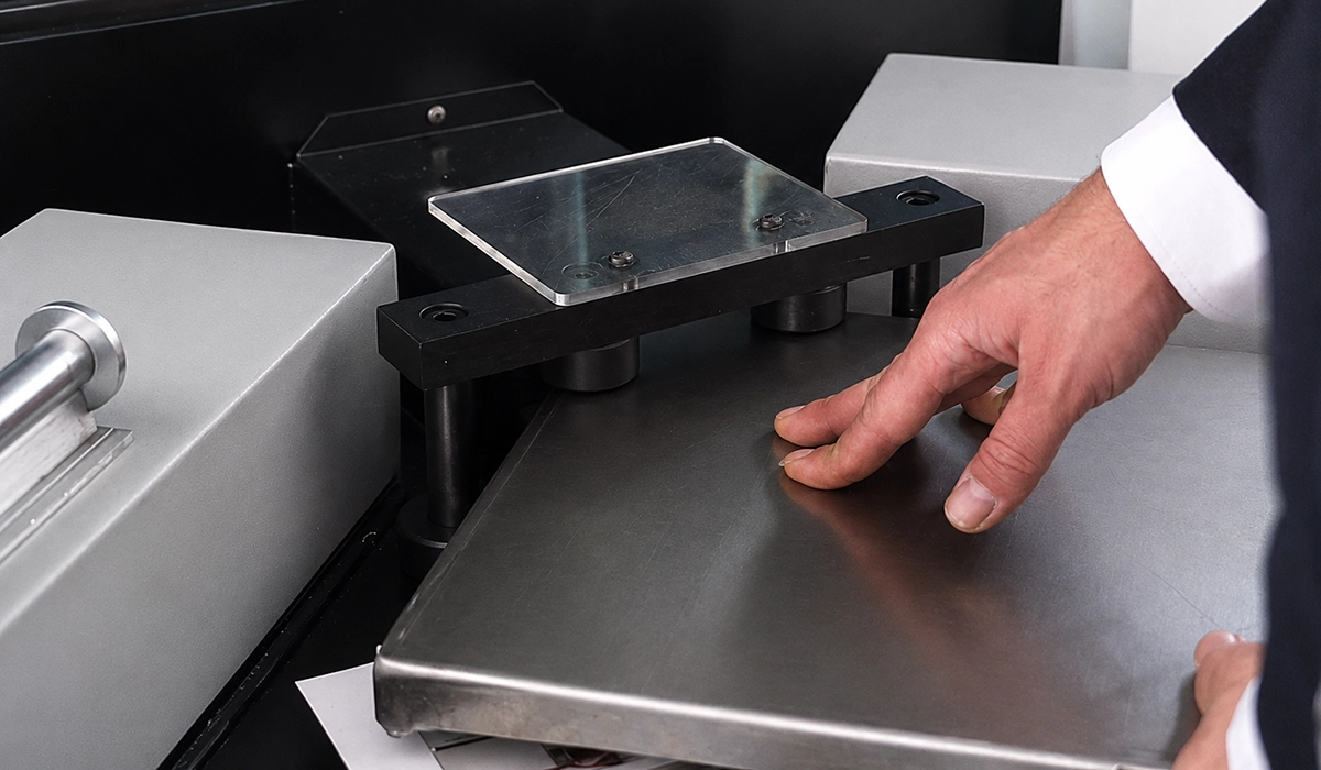
- Seat the pre-bent corner over the forming lower die, then pull both flanges tight against the die faces by hand.
- Engage the pneumatic sheet holder for large plates.
- Trigger the cycle. The forming roller upper die descends and rolls the flange material around the radius.
- The roller returns and all parts retract to home position.
Step 2 carries most of the outcome. Anyone asking how to set the die gap already has the answer built into the tooling. The gap equals roller radius minus sheet thickness, and it only works when the sheet sits in it. A slack flange rides in the wrong part of that gap. The roller then works the material unevenly, and you get a wavy radius that no downstream trimming will straighten.
A correctly formed corner leaves this step closed and even, with surplus flange material standing proud at the tip. That surplus is the shear allowance, and it comes off next. A corner that looks finished at this stage usually means the blank was cut short.
One safety point, stated plainly: hands come clear of the die area before the cycle starts. The pedal exists so both hands can hold the sheet during setup, not so the operator can rush.
For a clearer and more complete explanation, this page goes into far more depth than we can cover in a short text.

Step 2: Trimming
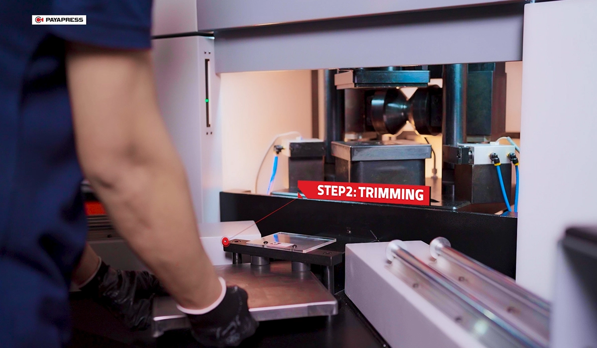
Trimming delivers a corner ready for powder coating with no grinding step, because the shear line follows the finished corner geometry rather than the original blank.
The operator reposition the panel at the shear station and runs the shear cycle. The knife takes off the standing flash and the scrap falls clear of the work area. Forming and trimming stay separate operations for a reason. The shear cannot know where to cut until the corner has taken its final shape. Trimming flash after corner forming is therefore the only sequence that produces a repeatable edge.
What comes off the machine is a uniform radius with a closed seam line, ready for pretreatment and coating.
Here is the operator insight worth remembering: a corner that needs deburring after trimming is telling you something. It is not a normal outcome of the process. Either the die gap is wrong for the thickness, or the knife clearance has drifted. Treat the burr as a diagnostic, not as extra work.
Changing Radius and Thickness (EH vs ES)
One rule governs changeovers on any cold forming corner machine, and knowing how to use a corner forming machine efficiently comes down to applying it. Same radius, different thickness: adjust the die gap. Different corner radius: change the roller die. Operators who confuse the two either force a mismatched gap or waste time changing the forming roller die when a gap adjustment would have done.
The two models differ only in how the first of those happens.
| Feature | CFCM-30EH | CFCM-30ES |
| Setting change per sheet thickness | Manual | Automatic |
| Thickness changeover | Operator adjusts dies by hand | Preset positions t = 1 / 1.25 / 1.50 / 2 mm, selected on the HMI |
| Digital angle indicator | — | Yes |
| Springback (elastic return) compensation | — | Yes, automatic |
| Changeover downtime | Higher — per-job manual setup | Minimal — select and run |
| Best fit | Stable product mix, few changeovers | Mixed thicknesses, frequent changeovers |
Everything else is shared: forming radius R6–R30 mm, 1,200 kg body, 4.5 kW total power, 200 bar hydraulics and a 7-inch HMI. Springback compensation for sheet metal corners is the practical divider. The ES holds the angle across grades without a test piece. The EH asks the operator to know the material.
If you would like to explore this subject further, you can read more about it here.
Pick on changeover frequency, not on capability. Both models form the same R6–R30 range across the same 0.5–2 mm band. If a shift runs one or two thicknesses and the radius rarely moves, the EH’s manual setup costs a few minutes a day. Once a shift crosses roughly three thickness changes, that setup starts eating more time than the forming itself, and the ES preset earns its place.
Either way, batch by radius. Group every job sharing a radius, run them together, and change the die once instead of four times.

Checking the Corner and Fixing What Goes Wrong
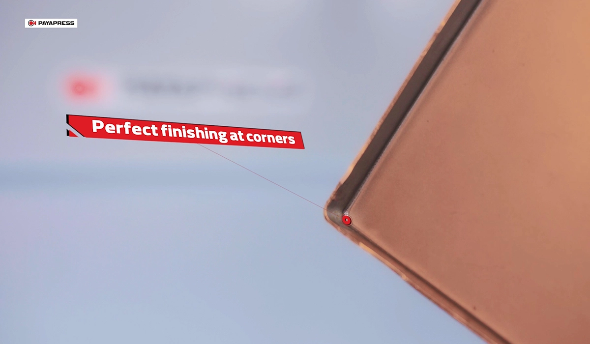
A correctly set machine holds all four corners of a panel to the same radius, and holds it from the first panel of a batch to the last. A radius gauge that passes on corner one and fails on corner three points at setup, not at the machine.
Check the corner the moment it leaves the shear, not at the end of the run. Every fault in the table below traces back to one of three places: the blank, the pre-bend, or the die setting. None of them are machine faults, and all three cost minutes to correct before the batch is cut. The symptoms listed are what an operator sees; the causes are what actually needs changing.
| Symptom | Likely cause | What to check |
| Uneven or wavy radius | Sheet not pulled tight to the die | Seating and holder pressure |
| Corner opens slightly after forming | Springback (material- and thickness-dependent) | Material grade vs thickness limits; ES compensation setting |
| Visible step at the corner tip | Wrong die gap for the thickness | Gap = roller radius − sheet thickness |
| Rough edge after trimming | Shear knife clearance or wear | Knife setting and edge condition |
| Inconsistent corners across one panel | Pre-bend angle varies between sides | Press brake setup upstream |
Run that quality check on the first part of every batch and again at the end. Two passing parts at either end of a run tell you the setup held throughout. Consistency, more than speed, is why this process displaces welding. A welded corner varies with the welder, the ground bead and the polish. A formed corner varies only with a setup you control, and that setup does not get tired at four in the afternoon.
Safety and Daily Maintenance
Keep hands clear of the die zone. The pedal frees your hands to position the sheet; it does not excuse positioning them badly. Know where the emergency stop sits before your first cycle, and use it for anything unexpected — a sheet slipping, an unusual noise, a person entering the die area.
Never run a sheet outside the stated thickness range for its material. Black ST37 below 1.5 mm will not form to a clean radius, and forcing it loads the tooling rather than the metal.
Daily maintenance on a corner forming machine is short. Check the hydraulic level in the 50 L tank, look at oil condition, and wipe the die faces clear of scale and debris. Periodically, inspect seals, the hydraulic pump, sensor function and the shear knife edge. Keep guard panels closed during every cycle.
Conclusion about How to Use a Corner Forming Machine
Knowing how to use a corner forming machine comes down to three decisions. Get the blank and the pre-bend right upstream, because the corner former never bends a wall. Seat the flange tight so the die gap does its job. Match the model to the job mix: the EH where thickness rarely changes, the ES where it changes every batch. The payoff is a corner that seats a gasket evenly, which is what an IP rating rests on.



Rate this article
Choose a rating from 1 to 5 stars.
No ratings yet