






If you’d rather listen than read, feel free to play the audio file below for the rest of this article.
What Is Sheet Metal Fabrication?
Sheet metal fabrication is the process of cutting, forming, joining, and finishing flat metal sheet into functional parts. The output is everything from a simple bracket to a complete electrical enclosure: panels, cabinets, doors, housings, trays, and frames.
The defining constraint is that the starting material is flat and of uniform thickness. Every feature in the finished part has to be created by removing material, bending it, or attaching something to it. That is what separates fabrication from casting or machining, where geometry can be created in three dimensions from the outset.
Almost all sheet metal forming happens cold, at room temperature, without heating the material—a process explained in more detail in our guide to cold forming in sheet metal. Heating flat stock is rare in this sector because it introduces distortion and scale that then have to be corrected.
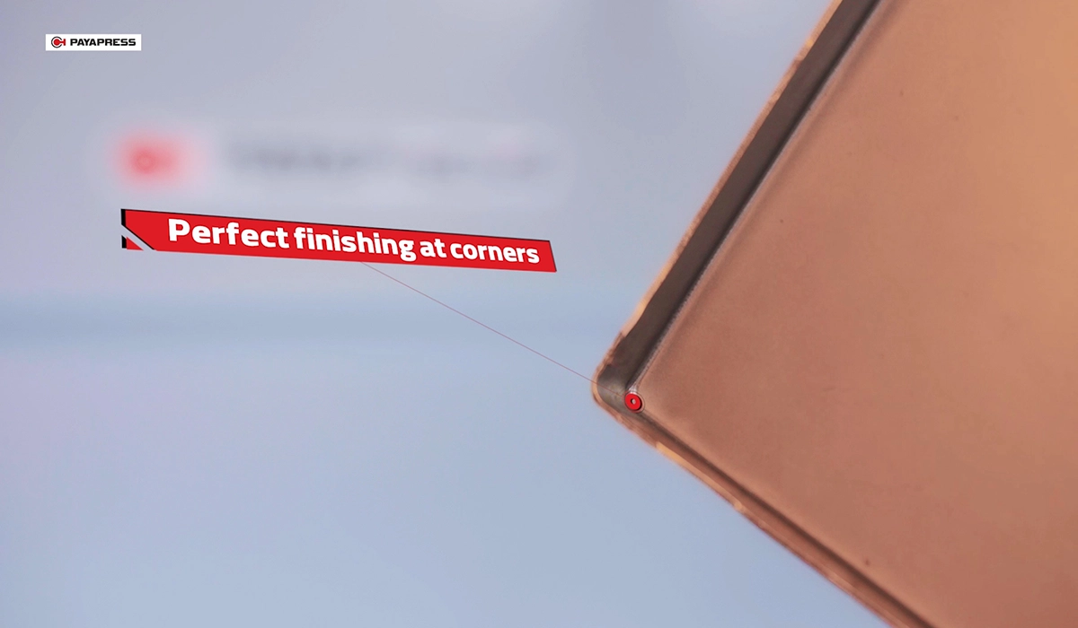
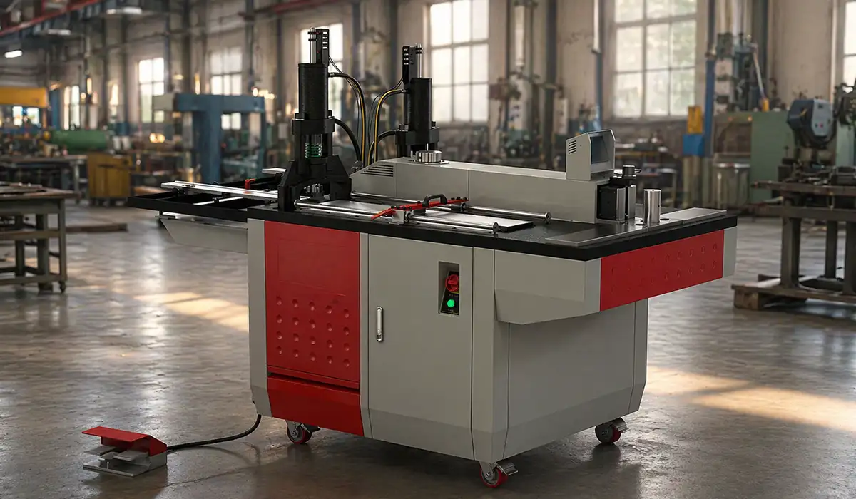
Before continuing to the details of cold forming sheet metal technology, we recommend taking a look at the corner forming machine — one of the products built on this technology. You can also watch the video below to see it in action.
The Process at a Glance
The route from CAD drawing to finished sheet metal part passes through seven defined stages. The table below sets out the steps in the sheet metal fabrication process alongside the equipment typically used at each one. Order can flex slightly between shops, but the dependencies do not.
| # | Step | What Happens | Typical Machine/Tool |
|---|---|---|---|
| 1 | Design & Drawing | CAD Model → Flat Pattern | CAD Software |
| 2 | Material Selection | Grade + Thickness Chosen | — |
| 3 | Cutting | Sheet Cut to Blank Shape | Shear, Punch, Laser |
| 4 | Bending & Forming | Bends, Flanges, Corners Formed | Press Brake, Corner Former |
| 5 | Joining & Assembly | Parts Connected | Welder, Riveter, Fasteners |
| 6 | Surface Finishing | Coating and Protection | Powder Coating Line |
| 7 | Quality Control | Checked Against Drawing | Measuring Tools |
Two stages carry no machine of their own. Design happens in software, and material selection is a purchasing decision—yet between them they determine most of what happens on the shop floor afterwards. The five machine-based stages are where cost and capacity live, but the two upstream stages are where quality is decided.
This downloadable guide gives you a more structured overview of the subject.
The 7 Steps of Sheet Metal Fabrication
The order can flex slightly by project, but the underlying logic is fixed. Cutting precedes bending, because a formed part cannot be fed flat through a shear or laser. Joining precedes finishing, because welding a coated part destroys the coating locally. Shops get into trouble when they reorder steps for scheduling convenience rather than process reasons.
Step 1—Design and Engineering Drawing
Fabrication starts on screen. A CAD model of the finished three-dimensional part is unfolded into a flat pattern, then exported as a machine-readable file — DXF for most cutting equipment.
Three practical details decide whether that drawing survives the shop floor. Bend allowance must be built into the flat pattern, since metal stretches on the outside of a bend and the flat length is not simply the sum of the leg dimensions. Minimum flange size must respect what the press brake tooling can actually grip. And hole-to-edge distance must be large enough that punching does not distort the edge or that bending does not deform the hole.
A drawing that gets these right prevents the large majority of shop-floor problems before they occur — one estimate puts it near 80% (hypothetical estimate). Tolerances should be stated explicitly rather than assumed.
If you want to see how this process works on a real machine, our complete guide to the metal forming machine.
Step 2—Material Selection
Grade and thickness are chosen against three criteria: mechanical strength, corrosion resistance, and budget. The choice then constrains every later step.
Cold-rolled steel is the default for general enclosure and panel work: economical, predictable in forming, and easy to coat. Stainless steel resists corrosion without coating and suits hygienic or outdoor applications, but it work-hardens faster, springs back more, and demands greater force at the same gauge. Aluminium is light and corrosion-resistant with low forming forces, though alloy and temper govern how tight a radius it will accept without cracking.
Thickness is the variable that propagates furthest. It sets cutting force, minimum bend radius, springback allowance, and whether the job fits the machine’s rated capacity at all. Substituting a higher-strength grade at the same nominal thickness is a frequent cause of unexpected machine overload, because the drawing thickness has not changed even though the required force has.
Step 3—Cutting: Shearing, Punching, Laser
Sheet metal cutting divides into three families. Shearing drives a blade through the sheet along a straight line, fast and economical for rectangular blanks. Punching uses a die set to remove material at specific locations, ideal for holes, slots, and repeated patterns. Laser cutting follows a programmed path, handling complex contours no mechanical tool can reach.
| Method | Precision | Speed | Best For | Limits |
|---|---|---|---|---|
| Shearing | Medium | Fast | Straight Cuts, Blanks | Straight Lines Only |
| Punching | High | Very Fast | Holes, Slots, Repeat Patterns | Tooling per Shape |
| Laser Cutting | Very High | Fast | Complex Contours, Prototypes | Cost, Thickness Limits |
Choose by the precision the part actually needs, the production volume, and the material thickness. A prototype enclosure justifies laser time that a thousand-off bracket does not, and a straight blank does not need a programmed path. Blanking — cutting the complete outline in one press stroke — sits between punching and shearing for high-volume work, trading tooling cost against cycle time.
Whichever method is used, deburring follows. Cut edges carry burrs that interfere with bending, damage downstream tooling, and injure handlers. Understanding how sheet metal parts are made cleanly starts here: an edge left rough at step 3 causes problems at every stage that follows.
Step 4—Bending and Forming
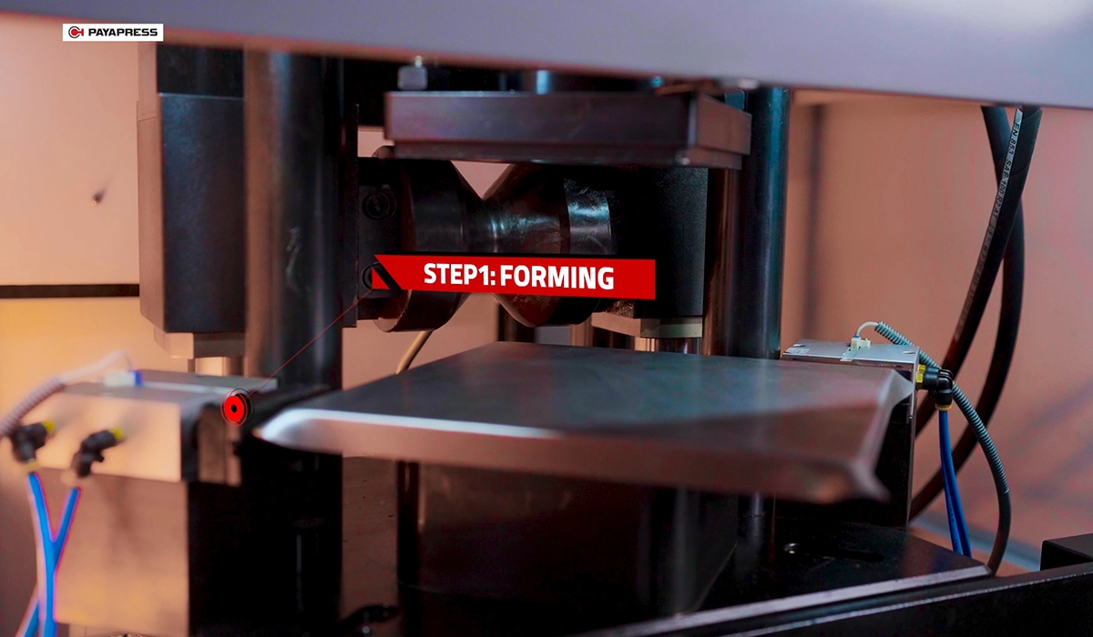
Sheet metal bending is where the flat blank becomes a three-dimensional part. A press brake drives a punch into a die to create a straight-line bend; folding machines achieve the same with a clamping beam and rotating blade. Both are cold processes.
Springback is the constant complication. Part of the deformation is elastic, so the metal relaxes slightly when pressure releases — a bend formed to exactly 90 degrees opens to 91 or 92. Tooling compensates by over-bending to a calculated allowance, and that allowance changes with material grade, thickness, and inside radius. Carrying an allowance over from a superficially similar job is a common source of out-of-tolerance angles, and it is why first-article checks matter most on this step.
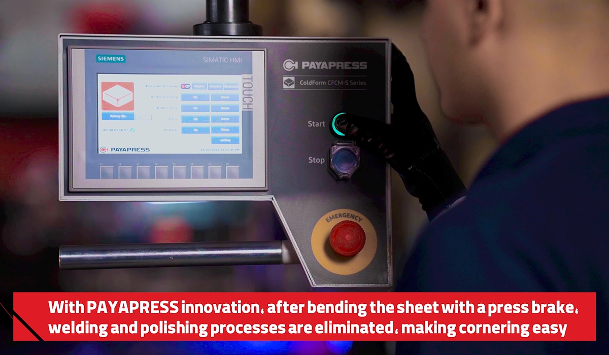
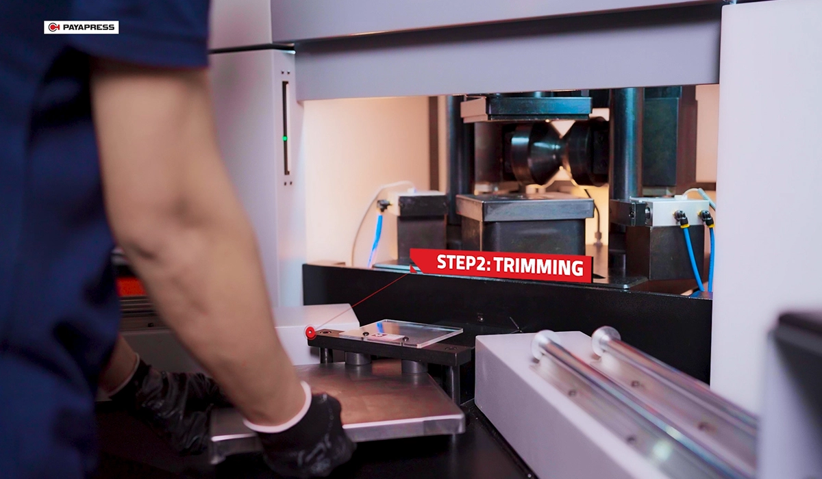
For enclosures, cabinet doors, and panel housings, a corner former machine performs an additional operation at this stage: it cold-forms a finished R-corner in one stroke, closing the joint between two flanges. That removes the welding step from the sequence entirely for those parts. The cost comparison is set out in our analysis of welding vs cold corner forming.
Cold forming covers more than bending — cutting and punching happen at room temperature too. See how automatic punching and shearing machines fit into a modern production line.
Step 5—Joining and Assembly
Four joining methods cover most sheet metal assembly, chosen against required strength, finish quality, and whether the joint must ever come apart.
| Method | Strength | Finish Quality | Rework Risk | Notes |
|---|---|---|---|---|
| Welding | Very High | Needs Grinding | Heat Distortion | Structural Joints |
| Riveting / Bolting | High | Clean | Low | Serviceable Joints |
| Formed Corners | High (Parent Metal) | Excellent, No Grinding | Very Low | Enclosures, Doors |
| Adhesives | Medium | Clean | Surface Prep Needed | Thin Sheet, Mixed Materials |
Serviceability is the question most often overlooked. A welded joint is permanent; a bolted or riveted one can be opened for maintenance. On enclosures housing equipment that will need access over a fifteen-year service life, that distinction outweighs a marginal strength advantage.
Is welding always needed in sheet metal fabrication? No. Formed corners and mechanical fastening replace it across many enclosure designs, removing both the heat input that causes distortion and the grinding that follows a bead. Welding remains necessary for structural joints carrying real load, for thick sections beyond forming range, and for geometries that tooling cannot reach. Choosing it by default rather than by requirement is what adds avoidable cost.
You can get the complete file here and use it as a practical working reference.
Step 6—Surface Finishing
Finishing exists for two reasons: corrosion protection and appearance. Bare steel begins oxidizing immediately, and most fabricated parts are visible in service.
The common options are powder coating, which applies electrostatic dry powder cured in an oven and dominates enclosure work; wet painting for large or heat-sensitive parts; anodizing for aluminium, growing a protective oxide layer; and plating or passivation for corrosion resistance without a color change.
One practical point governs cost here. Finishing quality depends almost entirely on the earlier steps. Grinding marks, weld spatter, and burrs all telegraph through a coating rather than hiding beneath it, and correcting them at the finishing stage costs several times what avoiding them upstream would have. Surface preparation before coating is not optional, and its extent is set by how cleanly the part arrived.
Save this downloadable resource for quick access whenever you need it.
Step 7—Quality Control and Delivery
Quality control checks the finished part against the drawing on three fronts: dimensional accuracy, visual finish, and functional fit where assemblies must mate.
Dimensional checks compare critical features to their stated tolerances. A realistic figure for a bent flange on general enclosure work is around ±0.2 mm (hypothetical estimate) [VERIFY against production data], though it varies with machine, tooling condition, and material.
ISO 9001-style documentation records what was measured, by whom, and against which revision of the drawing. That record matters most when a fault surfaces months later, because it establishes whether the part left the shop conforming or not. Packaging and delivery close the process, and freshly coated parts need transit protection that unfinished blanks never require.
The Machines Behind Each Step
Understanding which machines are used in sheet metal fabrication clarifies where capital investment actually changes output.
Step 3 belongs to cutting equipment: shears for straight blanks, turret or single-station punches for holes and patterns, and laser or plasma systems for contours. Capacity is set by thickness and sheet size.
Step 4 is press brakes and forming machines. Bend length and tonnage determine what the shop can accept, and control sophistication determines how quickly a job changes over. Corner formers sit here too, and they are the one machine that removes a later step rather than accelerating its own.
Step 5 uses welding equipment, riveting tools, and insertion presses for self-clinching fasteners. Steps 6 and 7 rely on coating lines and measuring equipment respectively.
Any sheet metal machine purchase should be assessed against the step it serves and, more importantly, the bottleneck it relieves. Adding cutting capacity to a shop constrained at bending moves the queue rather than shortening it. PAYAPRESS supplies corner former machine equipment within its wider machine range.
Holes and notches are usually cut into the sheet before bending begins. A punching and notching machine handles this step fast and with consistent repeatability.
Conclusion about Metal Fabrication Process
The sheet metal fabrication process runs from design and material selection through cutting, bending, joining, finishing, and quality control — seven steps in a fixed dependency order.
The pattern worth remembering is that most quality problems are created upstream and discovered downstream. A bend allowance error in step 1 surfaces as a mismatched assembly in step 5; a burr left in step 3 shows through the coating in step 6. Reviewing where a process creates faults, rather than where it catches them, is the fastest route to lower scrap.
Machines running high forming forces need consistent upkeep to stay accurate and safe. Our guide on punching machine maintenance and safety covers the key checks every operator should follow.



Rate this article
Choose a rating from 1 to 5 stars.
No ratings yet