
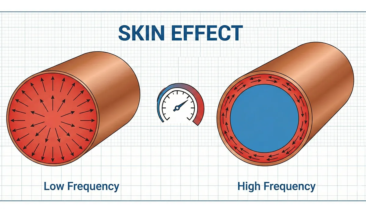
In the complex world of industrial electricity, power electronics, and high-frequency circuits, a phenomenon called the skin effect can create major challenges for optimal equipment performance. The skin effect causes alternating current (AC), especially at high frequencies, to concentrate on the surface of a conductor instead of distributing uniformly throughout its cross-section.
This phenomenon has a direct and significant impact on the efficiency of high-frequency capacitors, which play critical roles in industrial applications such as RF circuits, inverters, switching power supplies, telecommunication systems, and motor drives. But why do your high-frequency capacitors sometimes fail to deliver the expected performance? The answer often lies in the skin effect and incorrect equipment selection.
What Is the Skin Effect? Understanding the Fundamentals
The skin effect is a fundamental electrical engineering phenomenon that occurs in alternating current (AC) systems, particularly at high frequencies. It causes electric current, rather than spreading uniformly across the entire conductor cross-section, to concentrate mainly on the outer surface (skin) of the conductor.
The Physics Behind Skin Effect
The scientific mechanism behind this behavior is related to the interaction between magnetic fields produced by AC current and the conductor’s impedance characteristics at high frequencies. When AC flows through a conductor, it generates a time-varying magnetic field. This changing magnetic field, in turn, induces eddy currents within the conductor itself (due to Faraday’s law of electromagnetic induction).
These eddy currents create their own magnetic fields that oppose the original current flow in the conductor’s interior, effectively pushing the current toward the outer surface. As frequency increases, this effect becomes more pronounced—the current’s penetration depth (skin depth) decreases exponentially, and the current becomes confined to progressively thinner layers near the conductor’s surface.
Skin Depth Formula:
δ = √(2ρ / (ωμ))
Where:
• δ = Skin depth (meters)
• ρ = Resistivity of conductor (Ω·m)
• ω = Angular frequency (2πf)
• μ = Magnetic permeability (H/m)
• f = Frequency (Hz)
If the information related to topic Skin Effect was interesting and informative to you, researching topic All Types of Electrical Panels can be very engaging.
Visualizing the Skin Effect
Simply put, imagine the conductor as a hollow pipe: at high frequencies, current flows predominantly along the outer walls of the pipe, while the inner core becomes almost unused and electrically “dead.” This effectively reduces the conductor’s useful cross-sectional area, which increases its AC resistance (often called “effective resistance” or “RF resistance”).
Key Insight: While a copper conductor might have a DC resistance of 0.01 Ω, at 1 MHz the same conductor could exhibit an AC resistance of 0.15 Ω or higher—a 15x increase—due entirely to skin effect.
Real-World Example: High-Frequency Transformer Losses
In a 20 kHz switching power supply used in industrial welding equipment, engineers at Lincoln Electric discovered that copper busbars connecting high-frequency capacitor banks were experiencing excessive heating. Analysis revealed that at 20 kHz, the skin depth in copper is only 0.47 mm. Their 10mm diameter solid copper bars were effectively operating as 0.94mm thick hollow tubes, wasting 95% of the conductor material. Switching to Litz wire (multiple insulated strands) reduced losses by 62% and eliminated the thermal issues.
| Frequency | Skin Depth (Copper) | Skin Depth (Aluminum) | Effective Area (10mm wire) | Resistance Increase |
|---|---|---|---|---|
| 60 Hz (Power Line) | 8.57 mm | 10.94 mm | ~100% | Negligible |
| 1 kHz | 2.10 mm | 2.68 mm | ~85% | 1.2x |
| 20 kHz (Switching PSU) | 0.47 mm | 0.60 mm | ~38% | 2.6x |
| 100 kHz | 0.21 mm | 0.27 mm | ~17% | 6x |
| 1 MHz (RF) | 0.066 mm | 0.084 mm | ~5% | 19x |
| 10 MHz | 0.021 mm | 0.027 mm | ~2% | 60x |
How Does the Skin Effect Affect High-Frequency Capacitors?
The skin effect impacts high-frequency capacitor performance through multiple mechanisms, all of which contribute to reduced efficiency, increased losses, and potential reliability issues:
1. Increased Equivalent Series Resistance (ESR)
The most direct impact of skin effect is the increase in ESR (Equivalent Series Resistance) of the capacitor. ESR represents all the resistive losses in the capacitor, including:
- Terminal and lead resistance: At high frequencies, current concentrates on the surface of capacitor terminals and leads, dramatically increasing their effective resistance
- Internal electrode resistance: In multilayer ceramic capacitors (MLCCs) and film capacitors, the thin metal electrodes experience significant skin effect
- Connection interface resistance: Solder joints and crimped connections show increased resistance at RF frequencies
Real-World Impact: A high-quality film capacitor with 10 mΩ ESR at 1 kHz might exhibit 80-120 mΩ ESR at 1 MHz due to skin effect—an 8-12x increase in series resistance.
If the information related to topic ncreased Equivalent Series Resistance was interesting and informative to you, researching topic Underground Electrical Conduit can be very engaging.
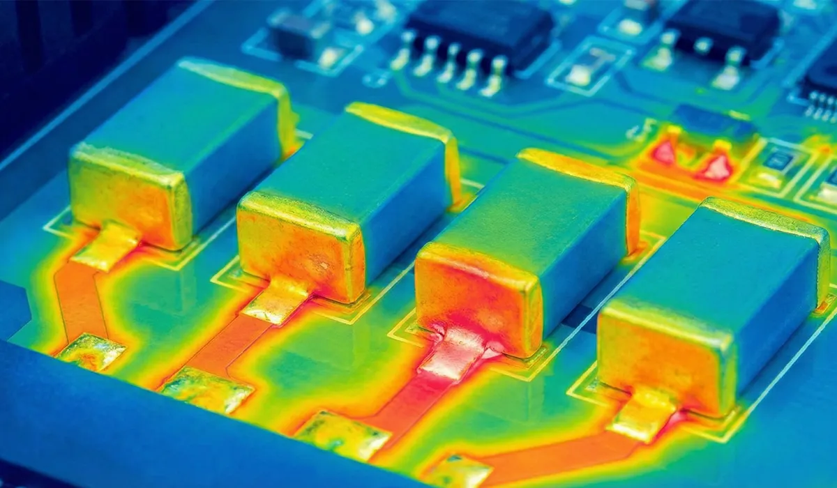
2. Excessive Heat Generation and Thermal Runaway Risk
Increased ESR leads to higher I²R losses (power dissipation). In high-current applications like inverters or switching power supplies, this can cause:
- Localized heating: Hot spots develop at terminals and connection points
- Accelerated aging: Every 10°C temperature increase can halve capacitor lifespan
- Thermal runaway: In extreme cases, heating increases ESR further, creating a positive feedback loop leading to failure
- Dielectric breakdown: Excessive heat can degrade the dielectric material, causing permanent capacitance loss or short circuits
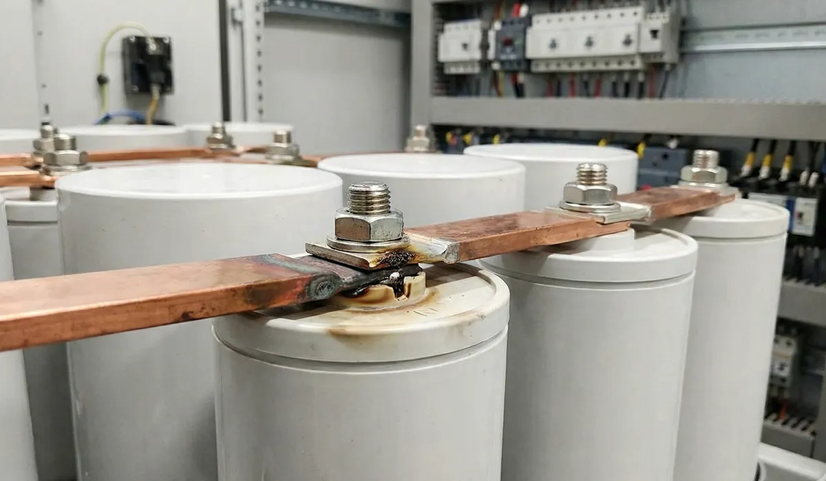
Real-World Failure Case: Industrial Inverter Capacitor Bank
A 500 kW variable frequency drive (VFD) at a water treatment facility experienced repeated failures of its DC link capacitor bank every 8-12 months, far below the expected 5-year lifespan. Thermal imaging revealed that capacitor terminals were reaching 95°C during operation (ambient 40°C). Investigation showed:
• The 16 kHz switching frequency created significant skin effect in the 6mm copper busbars
• RMS ripple current of 180A through these high-ESR connections generated 12W of heat per capacitor
• The cumulative effect reduced capacitor lifespan from 60,000 hours to under 10,000 hours
Solution: Replacing solid copper busbars with laminated copper sheets (0.3mm individual layers) reduced ESR by 70%, lowering terminal temperature to 65°C and extending capacitor life to the expected 5+ years.
Further exploration of Capacitance Effects can be found in the following recommended reading.
3. Voltage Drop and System Instability
In switching power supplies and inverters, increased ESR causes:
- Output voltage ripple: Higher ESR increases the AC voltage drop across the capacitor during switching transients
- Reduced filtering effectiveness: The capacitor’s ability to suppress high-frequency noise diminishes
- Control loop instability: Unexpected impedance changes can affect feedback control systems
- EMI/RFI issues: Poor high-frequency filtering allows electromagnetic interference to propagate
Example: In a 48V to 12V buck converter operating at 500 kHz, if the output capacitor’s ESR increases from 15 mΩ to 90 mΩ due to skin effect, the output voltage ripple increases from 45 mV to 270 mV—a 6x degradation in power quality.
4. Reduced Effective Capacitance at High Frequencies
While not directly caused by skin effect, the combination of increased ESR and equivalent series inductance (ESL) creates a phenomenon where the capacitor’s impedance increases at high frequencies, making it appear to have lower effective capacitance. This is critical in RF circuits and high-speed switching applications.
| Impact of Skin Effect | Low Frequency (< 1 kHz) | Medium Frequency (10-100 kHz) | High Frequency (> 1 MHz) |
|---|---|---|---|
| ESR Increase | Negligible (1.0-1.2x) | Moderate (2-5x) | Severe (10-50x) |
| Power Loss | < 1% | 3-8% | 15-40% |
| Temperature Rise | < 5°C above ambient | 10-25°C above ambient | 30-60°C above ambient |
| Filtering Effectiveness | Excellent (>90%) | Good (60-80%) | Poor (20-50%) |
| Expected Lifespan Impact | Normal (100%) | Reduced (50-70%) | Severely Reduced (20-40%) |
High-Frequency Capacitors: Types and Critical Role in Industrial Systems
High-frequency capacitors are vital components in industrial electrical equipment and modern power electronics, designed for optimal performance at frequencies ranging from tens of kilohertz to hundreds of megahertz. Understanding their role and characteristics is essential for engineers and facility managers.
Primary Applications in Industry
- RF (Radio Frequency) Circuits: Telecommunications, radar systems, broadcasting equipment (1 MHz – 300 MHz)
- Industrial Inverters: Variable frequency drives (VFDs), motor controllers (4-20 kHz)
- Switching Power Supplies: DC-DC converters, AC-DC rectifiers (20 kHz – 1 MHz)
- Induction Heating Systems: Industrial furnaces, brazing equipment (20-100 kHz)
- Telecommunication Systems: Base stations, signal processing, filters (100 kHz – 2 GHz)
- Pulse Power Applications: Laser power supplies, pulsed magnets, particle accelerators
Critical Characteristics of Quality High-Frequency Capacitors
1. Low ESR (Equivalent Series Resistance)
The single most important parameter for high-frequency applications. Low ESR ensures:
- Minimal power dissipation and heat generation
- Effective high-frequency filtering and decoupling
- Stable performance under ripple current loads
- Extended operational lifespan
Typical Values: < 10 mΩ at operating frequency for power applications, < 1 mΩ for RF applications
2. Low ESL (Equivalent Series Inductance)
ESL limits the capacitor’s effectiveness at very high frequencies. Every conductor has inductance, but high-frequency capacitors minimize it through:
- Short, wide terminals (surface mount designs)
- Multiple parallel internal connections
- Low-inductance construction (film stacks, MLCC arrays)
Typical Values: < 20 nH for power capacitors, < 1 nH for RF ceramics
3. High Ripple Current Rating
The ability to handle AC current without overheating. Critical in switching power supplies and inverters where large ripple currents flow.
Example: A DC link capacitor in a 100 kW inverter might need to handle 50-100A RMS ripple current at 16 kHz.
4. Temperature Stability
High-frequency operation generates heat. Quality capacitors must:
- Maintain stable capacitance over -40°C to +125°C range
- Exhibit low thermal resistance for efficient heat dissipation
- Use temperature-stable dielectric materials (C0G/NP0 ceramics, polypropylene film)
5. Long Service Life Under Harsh Conditions
Industrial environments demand reliability:
- 100,000+ hours rated life at maximum temperature
- Resistance to humidity, vibration, and thermal cycling
- Self-healing capability (in film capacitors)
This article serves as a valuable resource for those seeking detailed information on Industrial control system.
Case: 2 MW Solar Inverter Installation
A solar farm in Arizona initially specified budget film capacitors ($800/unit) for their DC link. After 18 months:• 23% of capacitors failed prematurely (avg. 14 months vs 10-year spec)
• Each failure caused 3-5 hours downtime = $8,000-$12,000 lost revenue
• Total replacement cost: $148,000 + $276,000 lost productionSwitching to premium low-ESR capacitors ($2,400/unit) with proper thermal management:
• Zero failures in 4+ years of operation
• Additional upfront cost: $128,000
• ROI payback: 10.8 months
• 5-year savings: $1.2+ million
| Capacitor Type | Frequency Range | Typical ESR | Ripple Current | Primary Application | Skin Effect Impact |
|---|---|---|---|---|---|
| Ceramic (MLCC – C0G) | DC – 1 GHz | 0.1 – 5 mΩ | Low | RF circuits, decoupling | Minimal |
| Ceramic (MLCC – X7R) | DC – 10 MHz | 2 – 20 mΩ | Medium | Switching PSU, inverters | Low |
| Film (Polypropylene) | DC – 1 MHz | 5 – 50 mΩ | High | DC link, power factor correction | Moderate |
| Film (Polyester) | DC – 100 kHz | 20 – 200 mΩ | Medium | Low-freq filtering, coupling | Moderate |
| Electrolytic (Aluminum) | DC – 100 kHz | 50 – 500 mΩ | High | Bulk filtering, energy storage | High |
| Mica Capacitors | 1 kHz – 500 MHz | 0.5 – 10 mΩ | Low | RF power amplifiers, transmitters | Minimal |
Minimizing the skin effect requires a multi-faceted approach combining proper material selection, optimized circuit design, and careful component specification. Here are industry-proven strategies:
1. Selecting Optimal Conductor Materials and Geometries
Silver-Plated Copper Conductors
Since current concentrates on the surface, using materials with the highest conductivity on the surface is ideal:
- Silver has 6% higher conductivity than copper (63 × 10⁶ S/m vs 59.6 × 10⁶ S/m)
- A thin silver plating (5-10 μm) provides the benefits without excessive cost
- Reduced surface resistance translates directly to lower ESR
- Real-world savings: 15-25% reduction in conductor losses at RF frequencies
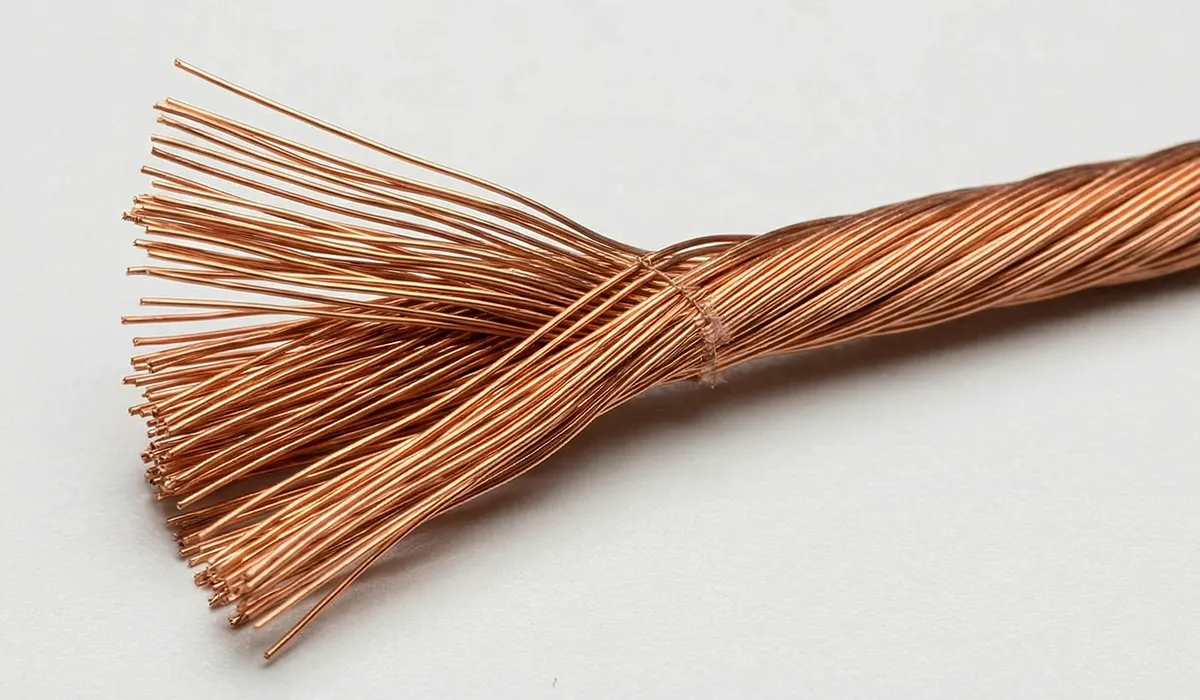
Litz Wire (Litzendraht)
For frequencies above 10 kHz, Litz wire dramatically reduces skin effect:
- Consists of dozens to thousands of individually insulated fine wire strands
- Each strand has diameter << skin depth, so current distributes uniformly within each strand
- Strands are woven to ensure each spends equal time at the bundle’s surface
- Effectiveness: Up to 90% reduction in AC resistance at 20-100 kHz
Example Application: Induction heating coils operating at 50 kHz use Litz wire with 500 strands of 0.1mm diameter wire. Compared to solid copper, losses are reduced by 85%.
If you are looking for more information about topic Litz Wire (Litzendraht), it is recommended not to miss reading this article.
Flat Conductors and Laminated Busbars
For power distribution in high-frequency systems:
- Flat conductors have higher surface area to volume ratio
- Laminated designs use multiple thin layers (0.1-0.5mm) insulated from each other
- This forces current to distribute across all layers, utilizing the conductor more effectively
- Additional benefit: Also reduces proximity effect in closely spaced conductors
If the information about topic Selecting Optimal Conductor was valuable and interesting to you, researching topic Wire Suitable for Industrial could be just as captivating.
A steel heat-treating facility upgraded their 25 kHz induction furnace power connections:Original Design:
• Solid copper busbars: 50mm × 10mm cross-section
• Measured ESR at 25 kHz: 125 μΩ/meter
• Power loss at 2,000A RMS: 500W/meter × 6 meters = 3 kW continuous loss
• Annual energy waste: 26,280 kWh ($2,628 at $0.10/kWh)After Laminated Busbar Upgrade:
• 20 layers of 0.5mm copper, insulated with 0.05mm polyimide
• Same overall dimensions (50mm × 10mm)
• Measured ESR: 28 μΩ/meter (78% reduction)
• Power loss: 672W total (78% reduction)
• Annual savings: 20,555 kWh = $2,055
• Upgrade cost: $4,200 → Payback: 2.04 years
2. Choosing Capacitors Engineered for High-Frequency Operation
Low-ESR Film Capacitors with Metalized Electrodes
Modern film capacitors address skin effect through design:
- Extended foil construction: Foil extends beyond the dielectric to create large-area contact surfaces
- Metalized film: Ultra-thin vacuum-deposited metal (0.02-0.05 μm) has minimal skin effect impact
- Multiple parallel sections: Internal structure creates parallel current paths
- Result: ESR < 5 mΩ at 100 kHz for power film capacitors
Multi-Layer Ceramic Capacitors (MLCC) with Controlled Geometry
MLCC construction naturally minimizes skin effect:
- Electrodes are extremely thin (1-3 μm), well below skin depth even at GHz frequencies
- Hundreds of parallel plates distribute current effectively
- Low-inductance packages: 0201, 0402 reverse-geometry designs minimize ESL
- Ideal for: High-frequency decoupling, RF bypass, switching power supply filtering
Hybrid Capacitor Banks
Combining capacitor types optimizes performance across frequency spectrum:
- Bulk electrolytic: Low-frequency energy storage (< 10 kHz)
- Film capacitors: Medium-frequency filtering (10-200 kHz)
- Ceramic capacitors: High-frequency decoupling (> 200 kHz)
- This approach ensures low impedance across the entire frequency range
3. Circuit Design Optimization Techniques
Minimize Current Path Lengths
- Shorter conductors = lower total resistance and inductance
- Place high-frequency capacitors as close as possible to the load
- Use surface-mount components to eliminate lead length
- Example: Moving decoupling capacitor from 50mm to 5mm from IC reduces ESL by 85%
Increase Conductor Width (for PCB Traces)
- Wider traces have more surface area, reducing current density
- For high-current paths, use maximum practical trace width
- Guideline: For every doubling of trace width, AC resistance decreases by ~35% at HF
Multi-Layer PCB Designs with Power/Ground Planes
- Solid copper planes distribute current over large areas
- Parallel plane structure creates low-inductance return path
- Reduces both skin effect and proximity effect
- Best practice: Dedicated power and ground planes with high-frequency capacitors connecting them
Frequency Spectrum Management
- Use the lowest practical switching frequency that meets requirements
- Implement soft-switching techniques to reduce harmonic content
- Add snubbers and damping networks to suppress ringing and high-frequency transients
| Solution Category | Specific Technique | Effectiveness | Best Application |
|---|---|---|---|
| Conductor Material | Silver-plated copper | 15-25% loss reduction | RF circuits, high-freq busbars |
| Conductor Geometry | Litz wire (multi-strand) | 60-90% loss reduction | Induction heating, transformers |
| Conductor Geometry | Laminated busbars | 50-80% loss reduction | Power distribution, inverters |
| Capacitor Selection | Low-ESR film capacitors | 70-85% ESR reduction | DC link, power factor correction |
| Capacitor Selection | MLCC arrays (parallel) | 80-95% ESR reduction | High-freq decoupling, RF |
| Circuit Design | Short, wide current paths | 30-50% loss reduction | PCB layout, busbar routing |
| Circuit Design | Multi-layer PCB with planes | 40-60% impedance reduction | Switching power supplies |
| Thermal Management | Active cooling (forced air) | 2-3x lifespan extension | High-ripple applications |
Why Industrial Facility Managers Need Skin-Effect-Optimized Electrical Panels
For industrial electrical contractors and facility managers specifying electrical panels, switchgear, and power distribution systems, understanding and mitigating skin effect is crucial for:
1. Operational Cost Reduction
- Energy efficiency: Reducing conductor losses by 50-80% through proper design can save thousands in annual electricity costs
- Example: A 500 kW VFD installation with optimized high-frequency conductors saves $8,000-$15,000 annually in reduced losses
- Reduced cooling requirements: Lower heat generation means smaller, less expensive HVAC systems for electrical rooms
2. Equipment Longevity and Reliability
- Extended component life: Proper thermal management doubles or triples capacitor and component lifespan
- Reduced failure rates: Optimized designs experience 60-80% fewer premature failures
- Lower maintenance costs: Fewer replacements and service calls
- ROI Example: Premium components with 2-3x upfront cost typically pay back in 1-3 years through reduced failures
3. System Performance and Power Quality
- Stable voltage regulation: Low-ESR designs maintain tighter voltage tolerances
- Reduced EMI/RFI: Better high-frequency filtering prevents electromagnetic interference
- Improved motor performance: Cleaner power to VFDs results in smoother motor operation and higher efficiency
- Compliance: Meets stringent power quality standards (IEEE 519, IEC 61000)
4. Safety and Code Compliance
- Reduced fire risk: Lower operating temperatures minimize thermal hazards
- Standards compliance: UL 508A, IEC 61439, NEC Article 310 requirements
- Insurance benefits: Some insurers offer reduced premiums for premium electrical installations
Diving into Topic Industrial Facility Managers? You’ll definitely want to give this article a look
Conclusion: Mastering Skin Effect for Optimal High-Frequency Performance
The skin effect is a fundamental electromagnetic phenomenon that significantly impacts the performance of high-frequency capacitors and electrical systems. By concentrating current on conductor surfaces, it increases effective resistance, generates excessive heat, and can contribute to premature component failure and system instability.
However, with proper understanding and application of proven mitigation strategies, these impacts can be dramatically reduced:
- Material selection: Silver-plated conductors, Litz wire, and laminated busbars reduce surface resistance
- Component specification: Low-ESR capacitors engineered for high-frequency operation minimize losses
- Circuit optimization: Short current paths, wide conductors, and multi-layer designs improve efficiency
- Thermal management: Proper cooling extends component life and maintains performance
For industrial electrical contractors, facility managers, and design engineers, investing in skin-effect-optimized components and systems delivers substantial returns through reduced energy costs, extended equipment life, improved reliability, and superior power quality.
Frequently Asked Questions (FAQ)
What is the skin effect in AC electrical systems?
The skin effect is a phenomenon where alternating current (AC), especially at high frequencies, concentrates near the outer surface of a conductor instead of distributing uniformly across its entire cross-section. This occurs due to electromagnetic induction effects that create opposing magnetic fields in the conductor’s interior, pushing current toward the surface. The result is increased effective resistance and reduced conductor efficiency.
Why does the skin effect become stronger at higher frequencies?
As frequency increases, the skin depth (the depth to which current penetrates) decreases exponentially according to the formula δ = √(2ρ/ωμ). At higher frequencies, the rate of change of magnetic field increases, creating stronger eddy currents that oppose current flow in the conductor’s interior. This forces more current into progressively thinner surface layers. For example, in copper at 60 Hz the skin depth is 8.57mm, but at 1 MHz it’s only 0.066mm—a 130x reduction.
How does the skin effect reduce high-frequency capacitor performance?
The skin effect increases the equivalent series resistance (ESR) of capacitor terminals, leads, and internal electrodes. This causes: (1) Increased power dissipation and heat generation (I²R losses), (2) Reduced filtering effectiveness due to higher impedance, (3) Greater voltage ripple in power supplies, (4) Accelerated aging and shortened lifespan due to elevated temperatures, and (5) Potential thermal runaway in extreme cases. A capacitor’s ESR can increase 10-50x at MHz frequencies compared to DC values.
What problems can excessive heat cause in high-frequency capacitors?
Excessive heat causes multiple failure modes: (1) Accelerated aging—every 10°C temperature rise approximately halves capacitor lifespan (Arrhenius relationship), (2) Dielectric degradation leading to capacitance loss and increased leakage current, (3) Thermal stress causing mechanical failures (cracks, delamination), (4) Electrolyte dry-out in aluminum electrolytics, (5) Increased ESR creating positive thermal feedback, and (6) In extreme cases, catastrophic failure including case rupture or fire. Operating a capacitor at 105°C instead of 85°C typically reduces life from 10 years to 2.5 years.
How do I calculate the skin depth for my application?
Use the formula: δ = √(2ρ/ωμ) where δ is skin depth in meters, ρ is resistivity (Ω·m), ω is angular frequency (2πf), and μ is magnetic permeability (4π×10⁻⁷ H/m for copper). For copper at room temperature (ρ = 1.68×10⁻⁸ Ω·m), this simplifies to: δ (mm) ≈ 66/√f(Hz). Examples: 60 Hz → 8.5mm, 20 kHz → 0.47mm, 1 MHz → 0.066mm. For effective current flow, conductor dimensions should be within 2-3x the skin depth. Beyond this, the additional material contributes minimal conduction.


