






Prefer listening? You can play the audio version of the rest of this article below.
What Is Voltage Drop?
Understanding electrical fundamentals helps engineers grasp why voltage drop occurs in every circuit. Explore core electrical fundamentals before diving into calculations and standards.
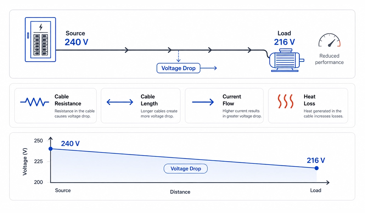
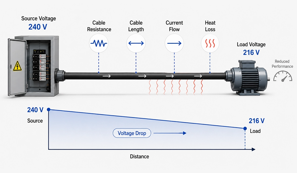
Voltage drop is the reduction in electrical potential that occurs when current flows through a conductor due to its inherent resistance. Every real conductor — wire, busbar, or terminal — carries some resistance. When current passes through that resistance, energy dissipates as heat, and the voltage at the load end falls below the source voltage.
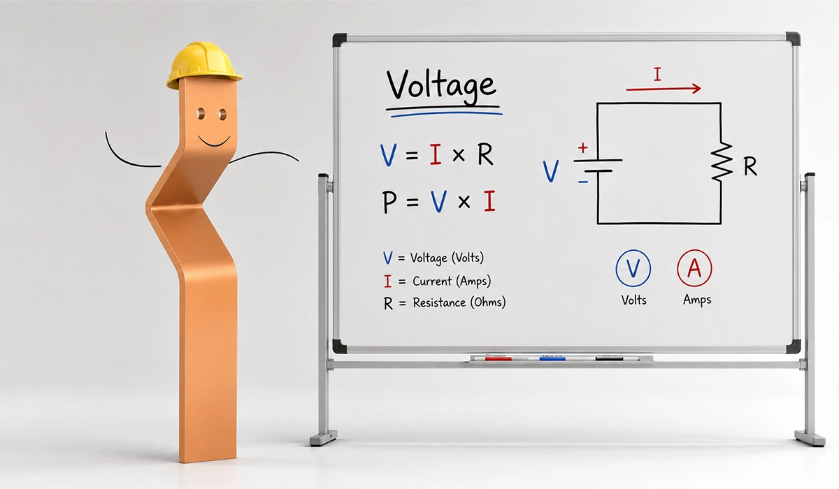
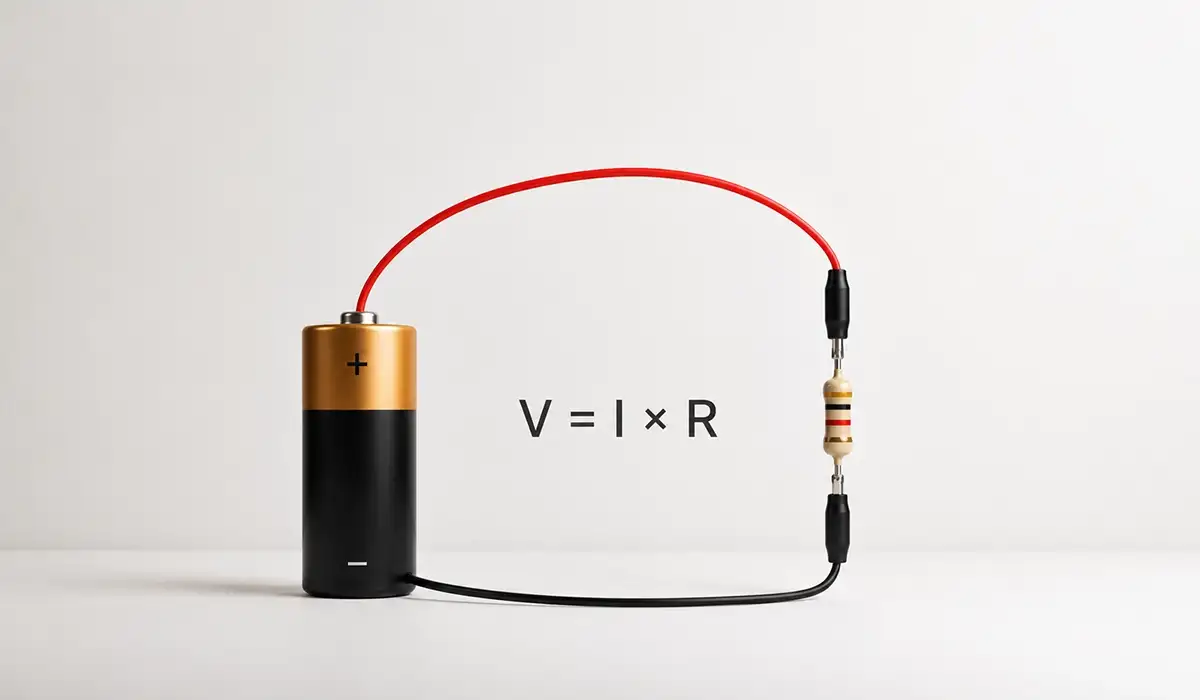
This phenomenon follows directly from Ohm’s Law: V = I × R. As current (I) crosses a resistance (R), some voltage (V) drops across it. Consequently, the loss is not a fault but a physical property of every real circuit.
Engineers quantify it as the difference between the supply voltage at the source and the voltage actually available at the load terminals. Typically, designers express the value either in volts or as a percentage of the nominal supply voltage.
Although a small loss is unavoidable, excessive drop causes measurable harm to equipment. Therefore, the design question is not whether one exists, but whether it stays within the limits set by code.
For this reason, standards such as NEC and IEC 60364 define maximum percentages so designers know where the safety boundary lies.
Every conductor’s behavior depends on voltage, current, and resistance working together. Learn what voltage, current, and resistance mean to understand these causes fully.
What Causes Voltage Drop?
Several physical mechanisms combine to produce the causes of voltage drop in real installations. Understanding each helps engineers make better choices about cable sizing, routing, and material selection.
Conductor resistance is the primary and unavoidable factor. Copper, aluminum, or any metal opposes current to some degree, converting electrical energy into heat. Resistance depends on resistivity, cross-section, and length — and copper offers about 40% lower resistivity than aluminum, which means smaller drop per meter for the same gauge.
Long cable runs amplify the effect, since cable resistance scales linearly with length. Therefore, doubling the run doubles the IR drop for the same current. Furthermore, the return conductor must enter the calculation, not only the one-way path.
High-current loads — large motors, welders, compressors — produce greater drop because the loss scales with current. During motor starting, inrush can reach five to ten times the running value, briefly creating severe transient sags on the supply.
Undersized conductors and poor terminations damage performance equally. Additionally, conductor resistance rises with temperature, so warm cables under sustained load worsen the problem further. Corroded lugs, loose torque, and aged crimps all add parasitic resistance at junction points.
The Voltage Drop Formula
The voltage drop formula derives directly from Ohm’s Law and varies with circuit topology. For DC and single-phase AC resistive circuits, the simplest expression is VD = I × R_total, where R_total includes both the outgoing and return conductors.
A more precise version uses material resistivity and conductor geometry: VD = (2 × L × I × ρ) ÷ A. Here, L is the one-way cable length in meters, ρ is resistivity in Ω·mm²/m, and A is conductor cross-section in mm². The factor of two captures the full circuit loop.
For three-phase balanced systems, the formula becomes VD = (√3 × L × I × ρ) ÷ A, where √3 accounts for phase geometry. Percentage drop then follows: VD% = (VD ÷ V_supply) × 100.
The table below summarizes the main variants, and a resistivity reference for the two common conductor materials follows directly after.
| Circuit Type | Formula | Notes |
|---|---|---|
| DC / Single-Phase (Basic) | VD = I × Rtotal | Rtotal Includes Both Conductors |
| DC / Single-Phase (Resistivity) | VD = (2 × L × I × ρ) ÷ A | ρ = Resistivity; L = One-Way Length |
| Three-Phase | VD = (√3 × L × I × ρ) ÷ A | √3 Accounts for Three-Phase Geometry |
| Percentage Drop | VD% = (VD ÷ Vsupply) × 100 | Compare Against Code Limits |
| Conductor Material | Resistivity (ρ) at 20°C | Relative Conductivity |
|---|---|---|
| Copper | 0.0172 Ω·mm²/m | Reference (100%) |
| Aluminum | 0.0282 Ω·mm²/m | ~61% of Copper |
These formulas trace back to a single foundational principle. Review Ohm’s Law fundamentals to understand exactly how voltage, current, and resistance interact mathematically.
Worked Example — Single-Phase Voltage Drop Calculation
Problem: A single-phase 230V circuit supplies a 20A load through a 50-metre copper cable with 4mm² cross-section.
Solution: VD = (2 × 50 × 20 × 0.0172) ÷ 4 = 34.4 ÷ 4 = 8.6V. Percentage = (8.6 ÷ 230) × 100 = 3.74%.
This marginally exceeds the NEC 3% branch-circuit guideline but meets the IEC 4% final-circuit limit. Upsizing to 6mm² yields 5.73V or 2.49%, comfortably within both standards.
Worked Example — Three-Phase Voltage Drop Calculation
Problem: A three-phase 400V circuit supplies a balanced 30A load through 75 m of 6mm² copper cable. This is a typical voltage drop calculator for three-phase circuits scenario.
Solution: VD = (√3 × 75 × 30 × 0.0172) ÷ 6 = 67.05 ÷ 6 = 11.18V. Percentage = (11.18 ÷ 400) × 100 = 2.79%.
The result sits within both NEC and IEC limits. At the load terminals, 388.82V remains — adequate for steady three-phase operation.
Voltage Drop Standards and Allowable Limits
Compliance with NEC and IEC limits protects equipment and ensures safe, reliable operation across residential, commercial, and industrial electrical installations worldwide.
Two major frameworks govern voltage drop in modern installations: the NEC in the United States and IEC 60364 internationally. Although both share similar numerical targets, their legal weight differs significantly. Engineers should understand the maximum allowable voltage drop IEC and NEC standards before specifying any conductor.
The NEC does not mandate a hard maximum value. Instead, Informational Notes in Articles 210 and 215 set the NEC recommended voltage drop for branch circuits at 3%, with the same 3% for feeders and a 5% combined ceiling. These remain guidelines, but most authorities having jurisdiction adopt them as design baselines.
In contrast, IEC 60364-5-52 sets enforceable limits: 3% for lighting circuits and 5% for power and motor circuits. Annex G of the standard provides the calculation method, and national annexes occasionally tighten these values further.
| Standard | Circuit Type | Recommended / Maximum | Status |
|---|---|---|---|
| NEC (NFPA 70) | Branch Circuit | 3% | Recommendation |
| NEC (NFPA 70) | Feeder | 3% | Recommendation |
| NEC (NFPA 70) | Feeder + Branch Combined | 5% | Recommendation |
| IEC 60364-5-52 | Lighting Circuits | 3% | Mandatory |
| IEC 60364-5-52 | Power / Motor Circuits | 5% | Mandatory |
| Good Engineering Practice | Any Critical Circuit | 2–3% | Best Practice |
Most industrial designers target 2–3% maximum loss on any single circuit, regardless of jurisdiction — leaving margin for future load growth and aging conductors.
Effects of Excessive Voltage Drop on Equipment and Systems
Excessive voltage loss creates real operational consequences that engineers see daily in motor failures, dim lighting, and erratic electronics. Each load type responds differently, so the design implications vary by application.
Electric motors are the most sensitive common load. Torque scales with the square of supply voltage, so a 10% sag cuts available torque by roughly 19%. The motor then draws higher current to maintain speed, overheating windings and accelerating insulation breakdown. During starting, inrush amplifies the problem and can prevent the motor from reaching running speed.
Lighting also suffers. Incandescent and halogen lamps follow a cube-law relationship — a 5% reduction yields about 14% less light output. LED and fluorescent fittings tolerate more variation but still drift outside their design band when supply falls too low.
Electronic equipment such as PLCs, HMIs, and VFDs typically allows ±10% tolerance. When line loss pushes supply outside that window, nuisance trips, communication errors, and shutdowns follow. Inside crowded control panels, even short wiring runs can contribute meaningful potential drop.
Resistive heaters lose output proportional to the square of voltage. Furthermore, overall system efficiency falls because the energy converted to heat inside the cable never reaches the load — a direct, measurable cost penalty.
For broader context, this external resource can help you continue your research.
Voltage Drop in Specific Applications
Voltage drop behaves differently across applications, and the cable sizing strategy must reflect each load’s tolerance and operating profile. Motors, control panels, and long distribution runs each impose unique constraints that one-size-fits-all design rules cannot capture.
In industrial facilities, three application contexts dominate practical engineering work: motor circuits with high inrush, low-voltage control panels with tight tolerance bands, and long-distance feeds to remote loads. Furthermore, each scenario demands a tailored approach to conductor selection.
Motor circuits combine the highest currents with the most voltage-sensitive load type. Therefore, engineers must assess both running and starting conditions, since starting inrush can briefly create severe transient sags. Control panel wiring, although typically short, often operates at 24VDC where even a small absolute drop becomes a large percentage of nominal voltage.
Long cable runs, finally, frequently see voltage drop in electrical cables become the governing design criterion rather than ampacity. In such cases, drop limits drive a conductor size well above what thermal capacity alone would require.
The subsections below examine each context in detail, with specific considerations and design rules that experienced installation engineers apply. Moreover, the same fundamental principles — Ohm’s Law, cross-section, length, and current — explain every case consistently.
Application requirements vary significantly by circuit type. Compare single-phase and three-phase power to choose the right design approach for each load.
Voltage Drop in Motor Circuits
Motor circuits demand the most careful analysis because motors combine high current with high voltage sensitivity. Engineers must evaluate both running and starting conditions: transient drops of 10–15% during inrush remain acceptable provided the motor still accelerates to running speed.
For long runs from a motor control center to a remote motor, the cable size is typically governed by drop rather than ampacity. Furthermore, variable frequency drives partially solve this problem by controlling acceleration current, easing transient stress on the supply network.
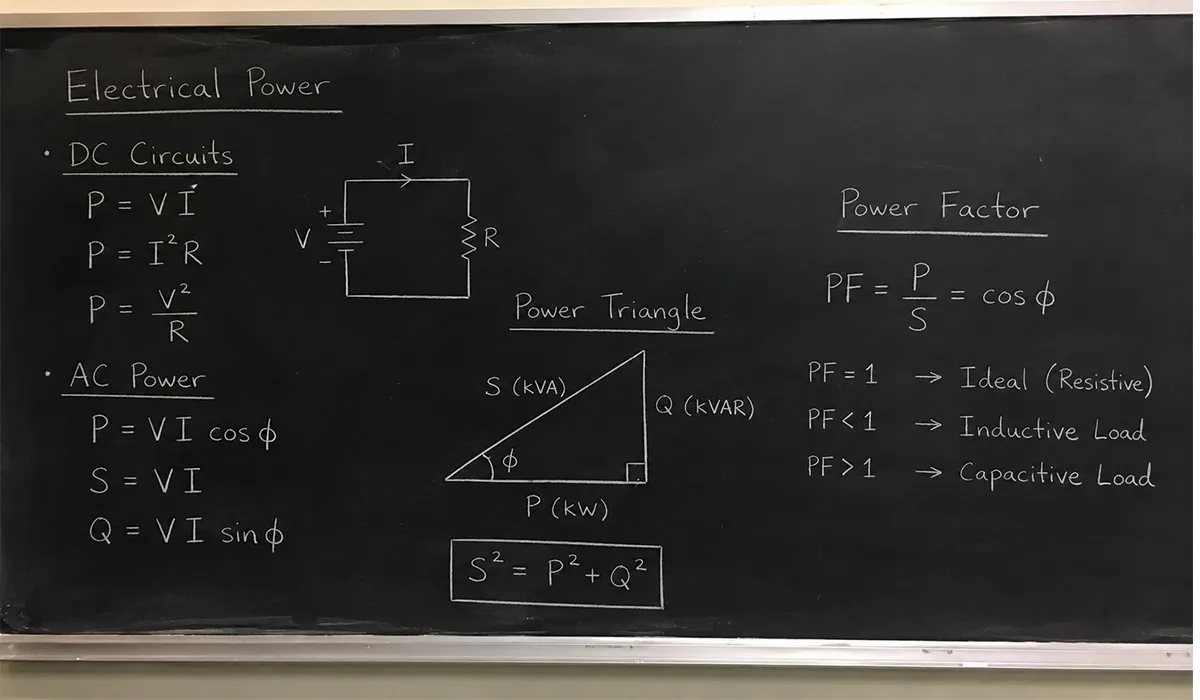
Motor sizing and voltage drop calculations both rely on accurate power figures. Review the electrical power formula for precise motor circuit design.
Voltage Drop in Control Panel Wiring
Inside crowded industrial panels, internal wiring resistance is easy to overlook. However, on 24VDC control circuits feeding solenoids, relays, and remote sensors, even a 1–2V loss represents 4–8% of nominal — pushing some devices outside their reliable operating band.
To fix voltage drop in industrial control panels, calculate the full loop length including return conductors, prefer larger cross-sections on long DC runs, and use thermal imaging on energized panels to find hot-spot connections before failure.
Accurate voltage and current readings matter most in sensitive 24VDC circuits. Learn about RMS voltage and current for precise panel measurements.
Voltage Drop in Long Distribution Cable Runs
Long feeders demand careful planning to minimize losses, protect equipment, and maintain stable voltage across remote pumps, lighting, and agricultural power supplies.
Long distribution feeds to outdoor lighting, remote pumps, or agricultural supplies frequently force cable sizes well above what ampacity alone would dictate. Here, the IR drop becomes the governing constraint rather than thermal capacity.
Three practical responses exist: intermediate distribution points, local step-up/step-down transformers, or higher distribution voltage. Transmitting the same power at higher voltage cuts current proportionally, reducing line loss as I × R — the most efficient long-run strategy where regulations permit.
How to Reduce Voltage Drop: Practical Strategies
Applying these five practical levers together delivers the greatest reduction in system losses, improving reliability, efficiency, and long-term equipment lifespan significantly.
Reducing voltage drop is essentially a matter of lowering resistance, current, or both. Engineers have five practical levers to pull, and the right choice depends on installation constraints and project budget.
First, increasing conductor cross-section is the most direct fix. Upsizing from 4mm² to 6mm² copper cuts resistance — and the resulting loss — by 33%. For long cable runs and critical loads, this is almost always the correct decision despite the higher material cost.
Second, shortening cable runs is equally effective and often cheaper over the system lifecycle. Distributed architecture — multiple smaller boards close to load clusters — beats a centralized panel with long radial feeds. Every meter removed eliminates the IR contribution of that meter.
Third, raising distribution voltage cuts current for the same power, reducing line loss proportionally. Where codes permit 400V or 480V instead of 230V or 120V, the saving compounds across every meter of cable. Furthermore, three-phase distribution to large loads exploits this principle inherently.
Fourth, switching from aluminum to copper conductors reduces resistivity by roughly 40%. Finally, clean, correctly torqued terminations remove parasitic resistance at every junction — a frequent culprit in aging installations and routine maintenance audits.
To explore the topic in greater depth, review the information available on this website.
Conclusion Voltage Drop
Careful conductor sizing, adherence to code limits, and routine maintenance keep every installation safe, efficient, and reliable for decades of continuous industrial operation.
Voltage drop is a fundamental, unavoidable feature of every electrical installation, but unmanaged loss costs facilities real money in damaged motors, dim lighting, and unreliable electronics. The physics is simple — Ohm’s Law applied to the resistance of every wire, terminal, and busbar in the circuit. The engineering, however, lies in balancing cost, conductor size, route length, and code limits to keep losses inside acceptable bands.
Designers who apply the NEC 3%/5% guidance or the IEC 60364 mandatory limits as design targets, who verify with the calculation formulas presented above, and who audit terminations during commissioning will avoid the majority of operational problems. Moreover, for long runs, motor feeders, and 24VDC control wiring, a conservative 2–3% design target buys real margin against future load growth and aging — a small upfront investment that pays back across the full life of the installation.
FAQs Voltage Drop
Below are answers to the most common questions readers ask about voltage drop calculations, acceptable limits, causes, and practical solutions for various installations.



Rate this article
Choose a rating from 1 to 5 stars.
No ratings yet