Scope & Applicability
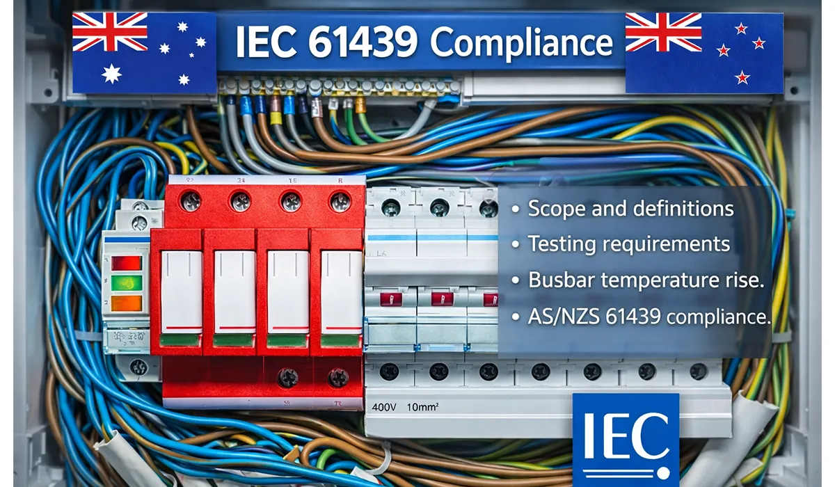
The IEC 61439 standard — and its Australian/New Zealand counterpart AS/NZS 61439 — covers low voltage switchgear and controlgear assemblies. These are the panels, boards, and enclosures that distribute and control electrical power in buildings, industrial plants, data centres, and infrastructure projects. If you work with electrical cabinets rated up to 1000 V AC or 1500 V DC, this standard applies to you. For a broader overview, see our guide on switchgear busbar standards.
The standard is split into several parts. Each part targets a specific type of assembly:
| Description | Part |
|---|---|
| General rules — definitions, ratings, and the verification framework that all other parts rely on | IEC 61439-1 |
| Power switchgear and controlgear assemblies — industrial and commercial distribution boards | IEC 61439-2 |
| Distribution boards intended to be operated by ordinary persons (household/similar) | IEC 61439-3 |
| Assemblies for construction sites (ASC) | IEC 61439-4 |
| Assemblies for power distribution in public networks | IEC 61439-5 |
| Busbar trunking systems (BTS) | IEC 61439-6 |
It is worth noting that IEC 61439 replaced the older IEC 60439 series. The difference between IEC 60439 and IEC 61439 is significant: the new standard introduced a structured three-path verification framework and clearer roles for manufacturers and assemblers. Many engineers and procurement teams still search for “IEC 439” or “IEC 60439,” but the current and applicable standard is IEC 61439.
If you’d rather listen than read, feel free to play the audio file below for the rest of this article.
Key Differences at a Glance — IEC 61439 vs AS/NZS 61439
AS/NZS 61439 is the Australian and New Zealand adoption of IEC 61439. The technical content is closely aligned, but there are important local additions and requirements that engineers working on AU/NZ projects must understand. Our electrical standards guide provides additional context on how international standards translate into local regulatory requirements.
The standard is harmonized with IEC 61439, which means the core technical rules — verification methods, temperature-rise limits, short-circuit ratings — are the same. However, AS/NZS 61439 adds context that ties the standard to the local regulatory environment. This includes references to AS/NZS 3000 (the Australian/New Zealand Wiring Rules), requirements around RCM (Regulatory Compliance Mark) administered by ACMA, and specific documentation and labelling expectations for the local market.
For companies exporting IEC 61439 panels from Europe or elsewhere into Australia or New Zealand, the evidence generated under IEC is often acceptable — but it must be properly mapped. You need to show clause-by-clause equivalence between your IEC evidence and the AS/NZS requirements. If any device is substituted, you need to confirm that power-loss and terminal temperature data remain within the tested limits, and that the enclosure size is not smaller than the reference design.
| AS/NZS 61439 (AU/NZ) | IEC 61439 (International) |
|---|---|
| RCM mark required for electrical safety and EMC compliance | Marking |
| References AS/NZS 3000 for installation clearances and access | Installation Rules |
| Local clause mapping document required when using IEC evidence | Evidence Transfer |
| ACMA regulates EMC/electrical safety pathway | Regulatory Body |
| CE marking is not recognised — RCM pathway must be followed | Market Access Mark |
Design Verification Methods
One of the most important concepts in IEC 61439 — and a major improvement over the old IEC 60439 — is the structured design verification framework. Under 61439, every assembly must have its design verified before it is placed on the market or put into service. For a detailed breakdown of this process for EU-market projects, refer to our design verification compliance guide. There are three accepted routes:
1. Verification by testing — A representative assembly is built and tested in a certified laboratory. The type tests cover temperature-rise, short-circuit withstand, dielectric withstand, IP rating, and more. This gives the strongest form of evidence and is ideal for standard, high-volume panel designs.
2. Verification by comparison — Your design is compared against a tested reference design. To use this route, your assembly must be equal to or more demanding than the reference. This means the enclosure must not be smaller, the device power losses must not be higher, the current ratings must not exceed those tested, and the arrangement must match. This method is commonly used by panel builders who work within an OEM’s tested family.
3. Verification by assessment (calculation) — You use engineering calculations and rules to demonstrate compliance. For example, temperature-rise can be assessed by calculating the total power losses, applying correction factors, and showing the result stays within the permitted ΔT limits. Short-circuit withstand can be assessed using let-through energy data from protective devices. This method requires solid engineering documentation but is widely used for custom or one-off assemblies.
Most real-world projects use a combination of all three methods. A panel builder might use type-test data from the enclosure OEM, comparison for the busbar arrangement, and calculation for the temperature-rise check on a modified layout.
Routine Verification Checklist
Unlike design verification — which is done once per design — routine verification is carried out on every single assembly before it leaves the workshop. This is a key requirement of IEC 61439 compliance and something inspectors and end clients will ask for. Part of this process involves confirming adequate protection against overcurrent is correctly implemented and documented for each unit.
Routine verification is not optional. It is a mandatory part of the standard and must be documented with traceable records tied to each assembly’s serial number or unique identifier.
| Notes | Routine Check Item |
|---|---|
| Visual check of wiring, terminal torques, and conductor sizing | Wiring Inspection |
| Verify air distances and surface paths meet design values | Creepage & Clearance |
| Check all doors, interlocks, and mechanical actuators operate correctly | Mechanical Operation |
| High-voltage dielectric test between live parts and earth | Dielectric Withstand |
| Low-resistance measurement of protective earth continuity | Protection Continuity |
| Verify nameplate data matches design and contract specification | Marking Check |
| Functional test of controls, interlocks, and protection relays | Function Tests |
Short-Circuit Withstand (Icw / Icc / Conditional SCC)
Short-circuit withstand is one of the most searched and most misunderstood topics in IEC 61439. The standard gives you several ways to express and verify this rating, and choosing the right one matters both for safety and for project compliance. Understanding how arc energy is managed during fault events is equally important — our article on internal arc type tests explains this in detail.
Icw (Rated Short-Time Withstand Current) — This is the peak current the assembly can withstand for a defined time (typically 1 second) without damage. It is the unconditional rating — no upstream protective device is assumed to help. This is the most conservative and most respected rating.
Icp (Rated Peak Withstand Current) — This covers the instantaneous peak during a fault, typically expressed as a multiple of Icw. The standard defines the relationship between Icw and Icp based on the power factor of the test circuit.
Icc (Conditional Short-Circuit Current Rating) — This is a conditional rating. The assembly is not expected to withstand the fault on its own. Instead, an upstream protective device (a fuse or circuit breaker) is specified to clear the fault. The combination is tested or assessed, and the result is the conditional rating of the assembly when protected by that specific device. This approach is common in practice because it allows lighter and more cost-effective busbar and enclosure designs.
When using conditional ratings, you must record the upstream device’s let-through energy (I²t) and let-through current. This data is used to verify that the components inside the assembly can survive the energy that gets through before the protective device clears the fault.
| Key Requirement | Rating Type |
|---|---|
| Tested or assessed without any upstream device assistance | Icw |
| Peak value — derived from Icw using standard power factor multipliers | Icp |
| Upstream device must be specified and its let-through data recorded | Icc |
Temperature-Rise & Rated Diversity Factor (RDF)
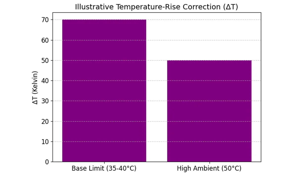
Temperature-rise is the most technically demanding part of IEC 61439 compliance. The standard sets limits in Kelvin (ΔT above ambient), not in absolute degrees Celsius. This is important: if your installation site has a higher ambient temperature than the standard’s reference (typically 35°C mean / 40°C max), you need to apply corrections. Best practices around thermal management during production are covered in our resource on busbar manufacturing safety.
The IEC 61439-1 temperature rise limits for busbars, terminals, and accessible surfaces are specific to each component type. For example, bare copper busbars have a maximum temperature-rise limit of 70 K, meaning at 35°C ambient the busbar must not exceed 105°C. Terminals connected to insulated conductors have tighter limits to protect the cable insulation.
IEC 61439-1 busbar sizing requirements are driven by these temperature-rise limits. You must calculate or test the total power dissipated inside the enclosure — from busbars, devices, cables, and any other heat-generating components — and show that airflow, spacing, and busbar cross-section are sufficient to keep temperatures within limits. This is the heart of the IEC 61439-1 busbar calculation process.
| Max Temperature Rise (ΔT) | Component |
|---|---|
| 70 K (bare copper or aluminium busbar) | Busbars |
| 70 K (for terminals of external insulated conductors) | Terminals (Cu conductor) |
| 30 K (intentionally touchable) / 40 K (not normally touched) | Accessible Surfaces |
| Per device manufacturer data sheet — must not exceed rated limits | Devices (MCCBs, contactors) |
The Rated Diversity Factor (RDF) accounts for the fact that not all circuits in a panel will carry full current at the same time. An RDF of 1.0 means every circuit is assumed to carry 100% of its rated current simultaneously — this is the worst case and requires the most robust thermal design. An RDF less than 1.0 (for example 0.8) means only 80% of circuits are at full load at once. Using RDF less than 1 is permitted but requires additional unit-level verification to demonstrate that individual circuits do not overheat under their specific load conditions.
Figure: Illustrative Temperature-Rise correction example (ΔT). Values are for explanation only; always verify with device data and the applied standard.
IEC 61439 Busbar Clearance — Creepage & Clearance
Clearance is the shortest straight-line distance through air between two conductive parts. Creepage is the shortest path along the surface of an insulating material between those same two parts. Both distances must be maintained at safe minimum values to prevent electrical breakdown — especially under transient overvoltages and in polluted environments. Understanding how pollution degree overvoltage categories interact is essential to setting the correct minimum distances for your assembly.
IEC 61439 busbar clearance requirements are derived from three main factors: the rated impulse withstand voltage (Uimp) of the assembly, the pollution degree of the environment (PD1 to PD4), and the material group of the insulating surface (defined by the Comparative Tracking Index, or CTI). Higher Uimp, heavier pollution, and lower CTI all require greater distances.
| Meaning | Parameter |
|---|---|
| Shortest path through air — governed by Uimp and overvoltage category | Clearance |
| Shortest path along insulator surface — governed by CTI and pollution degree | Creepage |
| PD1 (clean) to PD4 (highly conductive pollution) — affects required distances | Pollution Degree |
| Group I (>600), Group II (400–600), Group IIIa (175–400), Group IIIb (100–175) | CTI Material Group |
Good panel layout design starts with correct busbar spacing. Getting creepage and clearance right during the design phase avoids costly rework and helps the assembly pass the routine dielectric withstand test every time.
IP/IK Rating Selection
The IP (Ingress Protection) rating tells you how well an enclosure keeps out solid particles and water. The IK rating covers mechanical impact resistance. Both are important for IEC 61439 compliant enclosures and must be matched to the actual installation environment. A full comparison of these rating systems is available in our article on IP vs NEMA ratings.
For typical indoor panels in clean environments — offices, switch rooms, and light industrial — IP40 to IP55 is usually sufficient. For harsh outdoor environments, washdown areas, or dusty industrial sites, IP54 to IP66 is more appropriate. IK10 (rated for 20 joule impacts) is the most common choice for enclosures that could be subject to accidental knocks or vandalism.
| Typical Application | Rating |
|---|---|
| Clean indoor environments — office buildings, switch rooms | IP40 |
| Light industrial — dust present but not heavy, no direct water jets | IP54 |
| Washdown areas — food processing, chemical plants | IP65 / IP66 |
| Outdoor enclosures exposed to rain and dust | IP55 / IP65 |
| Robust enclosures — vandal risk or heavy industrial impact | IK10 |
This article serves as a valuable resource for those seeking detailed information on IP & IK Ratings Explained.
Forms of Internal Separation (Form 1 / 3B / 4A / 4B)
Forms of separation are one of the most frequently asked-about topics in IEC 61439. The form defines how well the busbars, functional units, and terminals are physically separated from each other inside the assembly. Higher forms reduce the risk of arc flash propagation and accidental contact with live parts when working on one part of the panel while another part remains energised. For further context on how separation requirements relate to switchboard construction standards, see our UL 891 switchboard guide.
Forms of separation as per IEC 61439 are defined in Annex BB of the standard. The four main forms are:
Form 1 — No internal barriers. All components share a common space. This is the most basic arrangement and is only suitable for simple, low-risk applications.
Form 2 — Busbars are separated from the functional units but terminals are not separated from busbars.
Form 3B — Busbars are separated from functional units. Functional units are separated from each other. Terminals are grouped in one area but not separated from each other.
Form 4A / 4B — The highest level of separation. Terminals are separated from functional units (4A) and also from each other (4B). This is the preferred form for critical installations, large industrial panels, and any application where live working or hot-swapping of modules is required.
| Key Feature | Form |
|---|---|
| No internal barriers — common open space | Form 1 |
| Busbars separated from functional units | Form 2 |
| Busbars + functional units separated from each other; terminals grouped | Form 3B |
| Full separation — terminals separated from functional units | Form 4A |
| Full separation — terminals also separated from each other | Form 4B |
EMC Immunity & Emissions
Electromagnetic compatibility (EMC) is part of the IEC 61439 compliance picture, especially when the assembly contains variable frequency drives (VFDs), switch-mode power supplies (PSUs), or other electronics that generate high-frequency noise. A thorough treatment of EMC requirements IEC 61000 for industrial control panels covers the immunity and emission limits that are most relevant in practice.
Industrial environments usually follow Class A emission limits, which are less strict than Class B (residential). However, the equipment must still be designed and verified not to cause interference with other systems and to be immune to interference from external sources.
Practical steps for EMC in IEC 61439 panels include keeping VFDs and PSUs filtered with proper EMC filters, using shielded cables for signal circuits, segregating power and control wiring, and bonding all metallic parts properly to earth. EMC evidence can be provided via component-level certificates from device manufacturers combined with a panel-level assessment, all stored in the verification pack.
Documentation & Marking
A compliant IEC 61439 or AS/NZS 61439 assembly must carry a durable nameplate and be supported by a complete verification record. The nameplate must show, at minimum, the rated operational voltage (Ue), the assembly current ratings (InA for the complete assembly, InC for individual circuits), the RDF, the short-circuit ratings (Icw, Icp, or Icc as applicable), the IP and IK ratings, and the parts of the standard applied (for example, AS/NZS 61439-1 and AS/NZS 61439-2). For panels being supplied into the European market in parallel, our guide on CE marking panels outlines the parallel documentation requirements under EU directives.
For AU/NZ projects, a Supplier’s Declaration of Conformity (SDoC) is required as part of the RCM pathway. This document declares that the product meets the applicable Australian standards and electrical safety/EMC requirements. It must be kept on file and be available for inspection by regulators.
| Details Required | Document / Item |
|---|---|
| Ue, InA, InC, RDF, Icw/Icc, IP, IK, standard reference | Nameplate |
| Design verification evidence — test reports, comparison records, calculations | Design Verification Pack |
| Per-unit test results linked to serial number or assembly ID | Routine Verification Records |
| Declares conformity with AS/NZS standards — required for RCM | SDoC |
| Required for all electrical and electronic products sold in AU/NZ | RCM Label |
RCM vs CE Pathway (ANZ)
CE marking is the European conformity mark. It shows that a product meets EU directives — Low Voltage Directive (LVD), EMC Directive, and so on. CE marking is legally required to sell products in the EU but has no legal standing in Australia or New Zealand. Engineers familiar with zone-based certification systems may also find it useful to compare how ATEX IECEx marking differs from both the CE and RCM pathways for hazardous area equipment.
For AU/NZ projects, the pathway is RCM — the Regulatory Compliance Mark. RCM is a single mark that covers both electrical safety (regulated by state and territory electrical safety regulators) and EMC (regulated by ACMA). To apply the RCM mark, manufacturers and importers must register with the ERAC responsible supplier database, hold a valid SDoC, and be able to demonstrate compliance with the applicable Australian standards.
IEC evidence (tests, assessments, comparison records) can form the technical basis of the SDoC for AU/NZ, but you must ensure that the evidence maps correctly to the AS/NZS version of the standard — not just the IEC version.
Can IEC Evidence Transfer to AS/NZS?
Yes — in most cases, IEC 61439 test evidence and verification records can be used as the technical basis for AS/NZS 61439 compliance. The key requirement is traceability: you must prepare a clause mapping document that shows, for each requirement in AS/NZS 61439, where your IEC evidence demonstrates compliance. Our dedicated AS NZS vs IEC guide walks through this mapping process step by step for low voltage assemblies.
If devices in the assembly are different from those used in the original type test, you need to check three things: first, that the power loss of the new devices is equal to or lower than the original; second, that the terminal temperature rise data from the new devices is equal to or lower; and third, that the physical arrangement and enclosure size are not smaller or more restrictive than the reference design.
If all three conditions are met, the substitution is valid and the original type test evidence can still be used. If any condition is not met, a new verification — by testing, comparison, or assessment — must be performed for the modified design.
Export Checklist EU → ANZ (Quick View)
If you are exporting IEC 61439 panels from Europe or another IEC-aligned market into Australia or New Zealand, use this checklist to make sure you have covered all the key requirements. Engineers new to AU/NZ compliance may also benefit from our plain English switchboard guide for a straightforward orientation to industrial assembly standards:
| Action Required | Item |
|---|---|
| Confirm evidence covers testing, comparison, or assessment per IEC/AS/NZS 61439 | Design Verification Evidence |
| Prepare traceable per-unit routine test records for all assemblies shipped | Routine Verification Records |
| Confirm Class A emissions and industrial immunity levels are covered | EMC Evidence |
| Update nameplate to show AS/NZS 61439-1/-2 and all required ratings | Nameplate / Marking |
| Register as responsible supplier and apply RCM mark with SDoC on file | RCM Pathway & SDoC |
| Include installation notes referencing AS/NZS 3000 clearances and access rules | Installation Documentation |
AS/NZS 3000 Clearances & Access
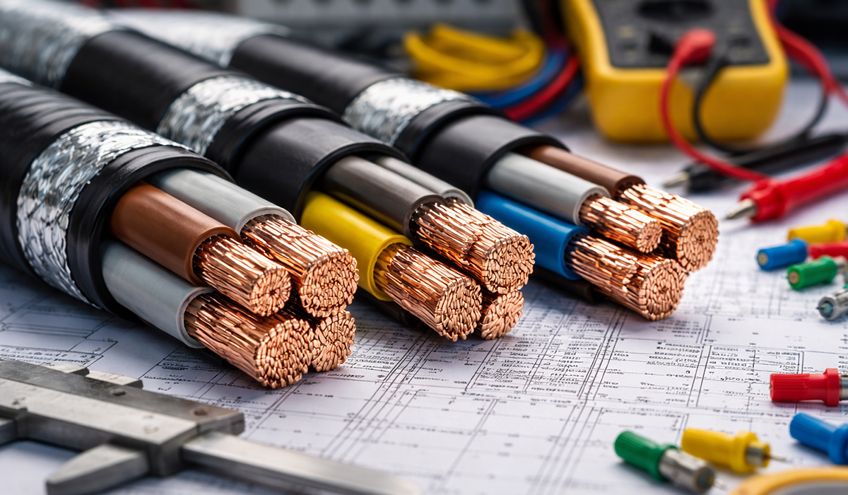
AS/NZS 3000 — commonly called the Wiring Rules — sets the requirements for how electrical installations must be designed and built in Australia and New Zealand. For switchboard and panel installations, it specifies minimum working space in front of and behind the board, door swing clearances, height limits for operating handles and switches, and requirements for safe approach distances during maintenance. Correct conductor selection is also part of this picture — our guide on electrical wires and cables covers the cable types most commonly used in compliant switchboard installations.
When you supply a panel for an AU/NZ project, your installation manual or drawing set should reference these requirements and help the installer meet them. Panels that are otherwise fully IEC 61439 compliant have been rejected on AU/NZ projects simply because the installation documentation did not address AS/NZS 3000 access requirements.
Manufacturer Responsibilities Under IEC 61439
IEC 61439 makes a clear distinction between two roles: the original manufacturer (often an OEM) and the assembler (often a panel builder or systems integrator). Understanding which role you are in is critical — because the roles carry very different responsibilities. Labelling obligations, including those triggered in the event of a fault, are also part of the manufacturer’s duty — see our quick reference on arc flash label requirements for what must appear on the finished assembly.
The original manufacturer designs the assembly, establishes the reference design, performs or commissions design verification (type tests, calculations, or comparisons), and produces the technical documentation. The original manufacturer takes responsibility for the design.
The assembler builds assemblies following the original manufacturer’s specifications and instructions. The assembler performs routine verification on each unit and keeps records. As long as the assembler follows the OEM’s instructions without modification, they rely on the OEM’s design verification.
However — and this is critical — if the assembler makes changes that go beyond the OEM’s defined scope (for example, adding extra devices, modifying the busbar arrangement, using a smaller enclosure), the assembler takes on manufacturer responsibility for those changes. This means they must perform new or additional design verification for the modified elements.
conclusion
In conclusion, IEC 61439 and AS/NZS 61439 provide a comprehensive framework for ensuring the safety, reliability, and efficiency of low voltage switchgear and controlgear assemblies. By adhering to these standards, manufacturers and engineers can ensure that their electrical assemblies meet essential requirements for design, verification, and documentation. The structured approach outlined in the standards helps minimize risks, enhance performance, and ensure compliance with local regulations, ultimately contributing to the successful implementation and operation of electrical systems in various industries. Understanding and applying these standards is crucial for anyone involved in the design, assembly, or procurement of electrical panels.